Table of Contents
Advertisement
Quick Links
S
DOUBLE-SIDED STORAGE
SC847 CHASSIS SERIES
SC847A-R1400LPB
SC847E1-R1400LPB
SC847E2-R1400LPB
SC847E16-R1400LPB
SC847E26-R1400LPB
SC847A-R1K28WB
SC847E26-R1K28WB
USER'S MANUAL
UPER
SC847E26-R1K28LPB
1.0c
SC847A-R1400UB
SC847E1-R1400UB
SC847E2-R1400UB
SC847E16-R1400UB
SC847E26-R1400UB
SC847E16-R1K28WB
SC847E16-R1K28LPB
®
Advertisement
Table of Contents

Related Manuals for Supero SC847 Series


Summary of Contents for Supero SC847 Series
- Page 1 UPER ® DOUBLE-SIDED STORAGE SC847 CHASSIS SERIES SC847A-R1400LPB SC847A-R1400UB SC847E1-R1400LPB SC847E1-R1400UB SC847E2-R1400LPB SC847E2-R1400UB SC847E16-R1400LPB SC847E16-R1400UB SC847E26-R1400LPB SC847E26-R1400UB SC847A-R1K28WB SC847E16-R1K28WB SC847E26-R1K28WB SC847E16-R1K28LPB SC847E26-R1K28LPB USER’S MANUAL 1.0c...
- Page 2 The information in this User’s Manual has been carefully reviewed and is believed to be accurate. The vendor assumes no responsibility for any inaccuracies that may be contained in this document, makes no commitment to update or to keep current the information in this manual, or to notify any person or organization of the updates.
- Page 3 Preface Preface About This Manual This manual is written for professional system integrators and PC technicians. It provides information for the installation and use of the SC847 chassis. Installation and maintenance should be performed by experienced technicians only. This manual lists compatible parts available when this document was published. Al- ways refer to the our Web site for updates on supported parts and configurations.
- Page 4 SC847 Chassis Manual Manual Organization Chapter 1: Introduction The first chapter provides a quick summary of the chassis features and a list of the available models with brief specifications. This chapter also includes contact information for Supermicro. Chapter 2: Warning Statements for AC Systems This chapter lists warnings, precautions, and system safety.
- Page 5 Preface The appendices list compatible cables, power supply specifications, and compat- ible backplanes. Refer to our Web site for the latest specifications and compatible backplane information. Appendix A: Hardware This section provides information on cabling, and other hardware which is compat- ible with your chassis.
-
Page 6: Table Of Contents
SC847 Chassis Manual Contents Chapter 1 Introduction Overview ......................1-1 Shipping List ....................1-1 Returning Merchandise for Service..............1-2 Contacting Supermicro ..................1-3 Chapter 2 Standardized Warning Statements for AC Systems About Standardized Warning Statements ............2-1 Warning Definition ................... 2-1 Installation Instructions .................. - Page 7 Preface Control Panel LEDs ..................4-2 Drive Carrier LEDs ..................4-4 SAS/SATA Drives .................... 4-4 SCSI Drives ..................... 4-4 Chapter 5 Chassis Setup and Maintenance Overview ......................5-1 Removing Power from the System ..............5-1 Removing the Chassis Cover ................. 5-2 Installing Removable Hard Drives..............
- Page 8 SC847 Chassis Manual Installing the Outer Rails on the Rack ............6-7 Standard Chassis Installation ................. 6-8 Optional Quick Installation Method ..............6-9 Adapters for Round and Threaded Hole Racks ........... 6-10 Chapter 7 Cascading Configurations Cascading Configuration Overview ..............7-1 Parallel Connectivity for Performance.............
-
Page 9: Chapter 1 Introduction
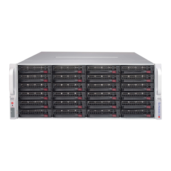
Chapter 1: Introduction Chapter 1 Introduction Overview Optimized for enterprise-level heavy-capacity storage applications, Supermicro's SC847 chassis features 36x (24 front + 12 rear) 3.5" hot-swap HDD bays used as a server chassis. The SC847 design provides high-density storage in a 4U form factor, with high power efficiency, optimized HDD signal trace routing and improved HDD carrier design to dampen vibration and maximize performance. -
Page 10: Returning Merchandise For Service
SC847 Chassis Manual SC847 Chassis 36x (server) SAS/ 4x FF + 3 1280W Redundant SC847A-R1K28WB SATA SAS2 support LP (WIO) (Platinum) SC84E16-R1K- 36x (server) SAS/ 4x FF + 3 1280W Redundant 28WB SATA SAS2 support LP (WIO) (Platinum) SC84E26-R1K- 36x (server) SAS/ 4x FF + 3 1280W Redundant 28WB... -
Page 11: Contacting Supermicro
Chapter 1: Introduction Contacting Supermicro Headquarters Address: Super Micro Computer, Inc. 980 Rock Ave. San Jose, CA 95131 U.S.A. Tel: +1 (408) 503-8000 Fax: +1 (408) 503-8008 Email: marketing@supermicro.com (General Information) support@supermicro.com (Technical Support) Web Site: www.supermicro.com Europe Address: Super Micro Computer B.V. Het Sterrenbeeld 28, 5215 ML 's-Hertogenbosch, The Netherlands Tel:... - Page 12 SC847 Chassis Manual Notes...
-
Page 13: Chapter 2 Standardized Warning Statements For Ac Systems
Chapter 2: Warning Statements for AC Systems Chapter 2 Standardized Warning Statements for AC Systems About Standardized Warning Statements The following statements are industry standard warnings, provided to warn the user of situations which have the potential for bodily injury. Should you have questions or experience difficulty, contact Supermicro's Technical Support department for assistance. - Page 14 SC847 Chassis Manual Warnung WICHTIGE SICHERHEITSHINWEISE Dieses Warnsymbol bedeutet Gefahr. Sie befinden sich in einer Situation, die zu Verletzungen führen kann. Machen Sie sich vor der Arbeit mit Geräten mit den Gefahren elektrischer Schaltungen und den üblichen Verfahren zur Vorbeugung vor Unfällen vertraut.
- Page 15 Warning Statements for AC Systems جسذٌة اصابة ًتتسبب ف حالة ٌوكي أى ًاًك ف خطز ًٌٌع هذا الزهز !تحذٌز الذوائز بالوخاطز الٌاجوة عي ي على علن ، ك هعذات تعول على أي قبل أى الكهزبائٍة حىادث أي وقىع وٌع ل الىقائٍة...
-
Page 16: Installation Instructions
SC847 Chassis Manual Installation Instructions Warning! Read the installation instructions before connecting the system to the power source. 設置手順書 システムを電源に接続する前に、 設置手順書をお読み下さい。 警告 将此系统连接电源前,请先阅读安装说明。 警告 將系統與電源連接前,請先閱讀安裝說明。 Warnung Vor dem Anschließen des Systems an die Stromquelle die Installationsanweisungen lesen. ¡Advertencia! Lea las instrucciones de instalación antes de conectar el sistema a la red de alimentación. -
Page 17: Circuit Breaker
Chapter 2: Warning Statements for AC Systems Circuit Breaker Warning! This product relies on the building's installation for short-circuit (overcurrent) protection. Ensure that the protective device is rated not greater than: 250 V, 20 A. サーキッ ト ・ ブレーカー この製品は、 短絡 (過電流) 保護装置がある建物での設置を前提としています。 保護装置の定格が250 V、... -
Page 18: Power Disconnection Warning
SC847 Chassis Manual 경고! 이 제품은 전원의 단락(과전류)방지에 대해서 전적으로 건물의 관련 설비에 의존합니다. 보호장치의 정격이 반드시 250V(볼트), 20A(암페어)를 초과하지 않도록 해야 합니다. Waarschuwing Dit product is afhankelijk van de kortsluitbeveiliging (overspanning) van uw electrische installatie. Controleer of het beveiligde aparaat niet groter gedimensioneerd is dan 220V, 20A. - Page 19 Chapter 2: Warning Statements for AC Systems ¡Advertencia! El sistema debe ser disconnected de todas las fuentes de energía y del cable eléctrico quitado de los módulos de fuente de alimentación antes de tener acceso el interior del chasis para instalar o para quitar componentes de sistema. Attention Le système doit être débranché...
-
Page 20: Equipment Installation
SC847 Chassis Manual Equipment Installation Warning! Only trained and qualified personnel should be allowed to install, replace, or service this equipment. 機器の設置 トレーニングを受け認定された人だけがこの装置の設置、 交換、 またはサービスを許可 されています。 警告 只有经过培训且具有资格的人员才能进行此设备的安装、更换和维修。 警告 只有經過受訓且具資格人員才可安裝、更換與維修此設備。 Warnung Das Installieren, Ersetzen oder Bedienen dieser Ausrüstung sollte nur geschultem, qualifiziertem Personal gestattet werden. -
Page 21: Restricted Area
Chapter 2: Warning Statements for AC Systems Waarschuwing Deze apparatuur mag alleen worden geïnstalleerd, vervangen of hersteld door geschoold en gekwalificeerd personeel. Restricted Area Warning! This unit is intended for installation in restricted access areas. A restricted access area can be accessed only through the use of a special tool, lock and key, or other means of security. -
Page 22: Battery Handling
SC847 Chassis Manual אזור עם גישה מוגבלת !אזהרה יש להתקין את היחידה באזורים שיש בהם הגבלת גישה. הגישה ניתנת בעזרת .)'כלי אבטחה בלבד (מפתח, מנעול וכד محظورة مناطق ٍنتركُبها ف هذه انىحذة تخصيص تم ،أداة خاصت من خالل استخذاو فقط محظورة... - Page 23 Chapter 2: Warning Statements for AC Systems Warnung Bei Einsetzen einer falschen Batterie besteht Explosionsgefahr. Ersetzen Sie die Batterie nur durch den gleichen oder vom Hersteller empfohlenen Batterietyp. Entsorgen Sie die benutzten Batterien nach den Anweisungen des Herstellers. Attention Danger d'explosion si la pile n'est pas remplacée correctement. Ne la remplacer que par une pile de type semblable ou équivalent, recommandée par le fabricant.
-
Page 24: Redundant Power Supplies
SC847 Chassis Manual Redundant Power Supplies Warning! This unit might have more than one power supply connection. All connections must be removed to de-energize the unit. 冗長電源装置 このユニッ トは複数の電源装置が接続されている場合があります。 ユニッ トの電源を切るためには、 すべての接続を取り外さなければなりません。 警告 此部件连接的电源可能不止一个,必须将所有电源断开才能停止给该部件供电。 警告 此裝置連接的電源可能不只一個,必須切斷所有電源才能停止對該裝置的供電。 Warnung Dieses Gerät kann mehr als eine Stromzufuhr haben. Um sicherzustellen, dass der Einheit kein trom zugeführt wird, müssen alle Verbindungen entfernt werden. -
Page 25: Backplane Voltage
Chapter 2: Warning Statements for AC Systems امداد الطاقة بوحدات عدة اتصاالت جهاز ال يكون لهذا قد الكهرباء عن وحدة ال لعسل كافة االتصاالت يجب إزالة 경고! 이 장치에는 한 개 이상의 전원 공급 단자가 연결되어 있을 수 있습니다. 이 장치에 전원을... -
Page 26: Comply With Local And National Electrical Codes
SC847 Chassis Manual מתח בפנל האחורי !הרה אז קיימת סכנת מתח בפנל האחורי בזמן תפעול המערכת. יש להיזהר במהלך .העבודה اللىحة أوالطاقة المىجىدة على التيار الكهزبائي مه خطز هناك هذا الجهاس خدمة كه حذرا عند يعمل النظام عندما يكىن 경고! 시스템이... -
Page 27: Product Disposal
Chapter 2: Warning Statements for AC Systems Attention L'équipement doit être installé conformément aux normes électriques nationales et locales. תיאום חוקי החשמל הארצי !אזהרה הציוד חייבת להיות תואמת לחוקי החשמל המקומיים והארציים התקנת المتعلقة المحلية والىطىية قىاويه يجب أن يمتثل لل الكهربائية... -
Page 28: Hot Swap Fan Warning
SC847 Chassis Manual ¡Advertencia! Al deshacerse por completo de este producto debe seguir todas las leyes y reglamentos nacionales. Attention La mise au rebut ou le recyclage de ce produit sont généralement soumis à des lois et/ou directives de respect de l'environnement. Renseignez-vous auprès de l'organisme compétent. - Page 29 Chapter 2: Warning Statements for AC Systems 警告 當您從機架移除風扇裝置,風扇可能仍在轉動。小心不要將手指、螺絲起子和其他 物品太靠近風扇。 Warnung Die Lüfter drehen sich u. U. noch, wenn die Lüfterbaugruppe aus dem Chassis genommen wird. Halten Sie Finger, Schraubendreher und andere Gegenstände von den Öffnungen des Lüftergehäuses entfernt. ¡Advertencia! Los ventiladores podran dar vuelta cuando usted quite ell montaje del ventilador del chasis.
-
Page 30: Power Cable And Ac Adapter
SC847 Chassis Manual Power Cable and AC Adapter Warning! When installing the product, use the provided or designated connection cables, power cables and AC adaptors. Using any other cables and adaptors could cause a malfunction or a fire. Electrical Appliance and Material Safety Law prohibits the use of UL or CSA -certified cables (that have UL/CSA shown on the code) for any other electrical devices than products designated by Supermicro only. - Page 31 Chapter 2: Warning Statements for AC Systems Attention Lors de l'installation du produit, utilisez les bables de connection fournis ou désigné. L'utilisation d'autres cables et adaptateurs peut provoquer un dysfonctionnement ou un incendie. Appareils électroménagers et de loi sur la sécurité Matériel interdit l'utilisation de UL ou CSA câbles certifiés qui ont UL ou CSA indiqué...
- Page 32 SC847 Chassis Manual Notes 2-20...
-
Page 33: Chapter 3 Chassis Components
Chapter 3: Chassis Components Chapter 3 Chassis Components Overview This chapter describes most common components included with your chassis. Installation instructions are detailed later in this manual. Components Drive Bays The chassis offers drive bays for thirty-six 3.5" hot-swap drives, with 24 in the front of the chassis and 12 in the rear. -
Page 34: Cooling
SC847 Chassis Manual Cooling The chassis includes redundant cooling with seven 8cm hot-swap fans plus an air shroud. Backplanes Backplanes support 36 SAS hard drives. The included backplanes support vary- ing drive types, depending on the chassis model and backplane model. Other Components Other components include a control panel with power switches and status LEDs, mounting rails, chassis intrusion switch, and an optional tray for mounting internal... -
Page 35: Chapter 4 System Interface
Chapter 4: System Interface Chapter 4 System Interface Overview There are LEDs on the control panel on the front edgre of the chassis, and others on the drive carriers to help monitor the activity and status of the system and com- ponents. -
Page 36: Control Panel Buttons
SC847 Chassis Manual Control Panel Buttons There are two push-buttons located on the left handle of the chassis. These are (in order from top to bottom) a power on/off button and a reset button. Power: The main power button is used to apply or remove power from the power supply to the server system. - Page 37 Chapter 4: System Interface NIC1: Indicates network activity on GLAN1 when flashing. NIC2: Indicates network activity on GLAN2 when flashing. Information LED: Alerts operator of several states, as noted in the table below. Informational LED Status Description An overheat condition has occured. Continuously on and red (This may be caused by cable congestion.) Blinking red (1Hz)
-
Page 38: Drive Carrier Leds
SC847 Chassis Manual Drive Carrier LEDs The SC847 chassis uses SAS or SATA drives. SAS/SATA Drives Each SAS/SATA drive carrier has two LEDs. • Blue: Solid on = Drive is present and available. Blinking = Drive is actively being accessed. Each Serial ATA drive carrier has a blue LED. -
Page 39: Chapter 5 Chassis Setup And Maintenance
Chapter 5: Chassis Setup and Maintenance Chapter 5 Chassis Setup and Maintenance Overview This chapter covers the steps required to install components and perform mainte- nance on the chassis. The only tool you will need to install components and perform maintenance is a Phillips screwdriver. -
Page 40: Removing The Chassis Cover
SC847 Chassis Manual Removing the Chassis Cover Figure 5-1. Removing the Chassis Cover Removing the Chassis Cover 1. If necessary, unplug the chassis from any power source 2. Remove the screws securing the cover to the chassis. 3. Lift the cover up and off the chassis. Caution: Except for short periods of time, do not operate the server without the cover in place. -
Page 41: Installing Removable Hard Drives
Chapter 5: Chassis Setup and Maintenance Installing Removable Hard Drives Figure 5-2. Removing Hard Drive Removing Hard Drive Carriers from the Chassis 1. Press the release button on the drive carrier. This extends the drive carrier handle. 2. Use the handle to pull the drive carrier out of the chassis. - Page 42 SC847 Chassis Manual Dummy Drive Drive Carrier Figure 5-3. Chassis Drive Carrier The drives are mounted in drive carriers to simplify their installation and removal from the chassis. These carriers also help to promote proper airflow for the drive bays. Caution: Except for short periods of time (while swapping hard drives), do not oper- ate the server with the drives removed from the chassis drive bays.
- Page 43 Chapter 5: Chassis Setup and Maintenance SAS/SATA Hard Drive Drive Carrier Figure 5-5. Installing the Hard Drive into the Carrier 2. Slide the hard drive into the carrier with the printed circuit board side facing down. 3. Carefully align the mounting holes in both the drive carrier and the hard drive. 4.
-
Page 44: Installing Optional Fixed Hard Drives
SC847 Chassis Manual Installing Optional Fixed Hard Drives The SC847 chassis includes brackets for installing either one 3.5" fixed hard drive, or two 2.5" fixed hard drives within the chassis. Each chassis can accommodate up to two internal drive brackets supporting up to two 3.5" hard drives or up to four 2.5"... - Page 45 Chapter 5: Chassis Setup and Maintenance Figure 5-8. Installing Single and Dual Hard Drives and the Bracket Installing a 3.5" Single Hard Drive into the Bracket 1. Align the four round washers and four screws with the holes in the hard drive and the holes in the bracket.
-
Page 46: Installing The Motherboard
SC847 Chassis Manual HARD DRIVE 3. Connect cables from the motherboard to the drives. Flat head Pan head 4. Slide the motherboard tray back into the chassis and secure it with the 6-32 x 5 mm 6-32 x 5 mm screws. - Page 47 Chapter 5: Chassis Setup and Maintenance Figure 5-10. Secure the Motherboard onto the Tray 4. Lay the motherboard on the tray aligning the permanent and optional stand- offs. 5. Secure the motherboard to the tray using the rounded, Phillips head screws. Do not exceed eight inch-pounds of torque.
-
Page 48: Expansion Card Setup
SC847 Chassis Manual Expansion Card Setup The chassis includes I/O slots for expansion cards. The number of cards used depends on your chassis model. SC847 LP Models: Provides seven low-profile expansion card slots. SC847 UIO Models: Provides three full-height/full-length slots, three low-profile slots and includes a universal expansion card. -
Page 49: Expansion Slot Setup In U (Universal Output) Chassis
Chapter 5: Chassis Setup and Maintenance Expansion Slot Setup in U (Universal Output) Chassis SC847 U model chassis accepts a slightly smaller "L" shaped motherboard to allow for a universal expansion card. This universal output card allows the systems to accept SAS, SCSI, IB, Ethernet, and other types of connections. -
Page 50: Installing The Air Shroud
SC847 Chassis Manual Installing the Air Shroud Figure 5-12. Air Shroud for SC847LP Chassis Air shrouds concentrate airflow to maximize fan effectiveness. The SC847 chas- sis air shroud does not require screws for its installation. The SC847 air shroud is designed with removeable break-away tabs that allow the air shroud to be adjusted to fit a variety of motherboards. -
Page 51: Checking The Server Air Flow
Chapter 5: Chassis Setup and Maintenance Checking the Server Air Flow Checking the Air Flow • Make sure there are no objects to obstruct airflow in and out of the server. In addition, if you are using a front bezel, make sure the bezel's filter is replaced periodically. -
Page 52: 5-10 System Fans
SC847 Chassis Manual 5-10 System Fans Seven hot-swappable, heavy-duty fans provide cooling for the chassis. These fans circulate air through the chassis thereby lowering the chassis internal tempera- ture. Release Tab Airflow Direction Indicator Figure 5-13. System Fan Replacing a System Fan 1. - Page 53 Chapter 5: Chassis Setup and Maintenance Figure 5-14. Placing the System Fan 5-15...
-
Page 54: 5-11 Power Supply
SC847 Chassis Manual 5-11 Power Supply The SC847 chassis has a redundant power supply. This power supply is auto- switching capable. This enables it to automatically sense and operate at a 100v to 240v input voltage. An amber light will be illuminated on the power supply when the power is off. -
Page 55: Chapter 6 Rack Installation
Chapter 6: Rack Installation Chapter 6 Rack Installation This chapter provides instructions for installing the chassis into a rack. . Unpacking the System You should inspect the box the chassis was shipped in, and note if it was damaged in any way. If the chassis itself shows damage, you should file a damage claim with the carrier who delivered it. -
Page 56: Rack Precautions
SC847 Chassis Manual Rack Precautions • Ensure that the leveling jacks on the bottom of the rack are fully extended to the floor with the full weight of the rack resting on them. • In single rack installations, stabilizers should be attached to the rack. •... -
Page 57: Rack Mounting Considerations
Chapter 6: Rack Installation Rack Mounting Considerations Ambient Operating Temperature If installed in a closed or multi-unit rack assembly, the ambient operating tempera- ture of the rack environment may be greater than the ambient temperature of the room. Therefore, consideration should be given to installing the equipment in an environment compatible with the manufacturer’s maximum rated ambient tempera- ture (TMRA). -
Page 58: Identifying The Sections Of The Rack Rails
SC847 Chassis Manual Procedure for Rack Mounting This section provides information on installing the chassis into a rack unit with the rails provided. There are a variety of rack units on the market, which may mean that the assembly procedure will differ slightly from the instructions provided. You should also refer to the installation instructions that came with the rack unit you are using. -
Page 59: Locking Tabs
Chapter 6: Rack Installation Locking Tabs Each inner rail has a locking tab. This tab locks the chassis into place when installed and pushed fully into the rack. These tabs also lock the chassis in place when fully extended from the rack. This prevents the server from coming completely out of the rack when when the chassis is pulled out for servicing. -
Page 60: Installing The Inner Rails On The Chassis
SC847 Chassis Manual Inner Rails Figure 6-3. Installing the Inner Rails Figure 6-4. Inner Rails Installed on the Chassis Installing The Inner Rails on the Chassis Installing the Inner Rails 1. Confirm that the left and right inner rails have been correctly identified. Place the inner rail firmly against the side of the chassis, aligning the hooks on the side of the chassis with the holes in the inner rail. -
Page 61: Installing The Outer Rails On The Rack
Chapter 6: Rack Installation L-min=676.00(26.61")(outer rail) 21D01 Figure 6-5. Extending and Releasing the Outer Rails Installing the Outer Rails on the Rack Installing the Outer Rails 1. Press upward on the locking tab at the rear end of the middle rail. 2. -
Page 62: Standard Chassis Installation
SC847 Chassis Manual Standard Chassis Installation Stability hazard. The rack stabilizing mechanism must be in place, or the rack must be bolted to the floor before you slide the unit out for servicing. Failure to stabilize the rack can cause the rack to tip over. Ball-Bearing Shuttle Figure 6-6: Installing into a Rack... -
Page 63: Optional Quick Installation Method
Chapter 6: Rack Installation 5. Slide the inner rails on the chassis into the middle rails, keeping the pressure even on both sides, until the locking tab of the inner rail clicks into the front of the middle rail, locking the chassis into the fully extended position. 6. -
Page 64: Adapters For Round And Threaded Hole Racks
SC847 Chassis Manual Adapters for Round and Threaded Hole Racks The SC847 chassis includes adapter brackets for those customers using round hole racks or racks with threaded holes size M5 or larger. Installing the Adapter Bracket 1. Place the hooks of the front of the outer rail into the square holes of one of the adapter brackets. -
Page 65: Chapter 7 Cascading Configurations
Safety Information and Technical Specifications Chapter 7 Cascading Configurations Cascading Configuration Overview The SC847 chassis backplanes can be configured in a variety of combinations for different applications. The following sections will provide connectivity configuration options specific to your system. Parallel Connectivity for Performance The following configuration increases the SC847's performance capabilities by utilizing parallel connectivity with SAS or SATA hard drives and a single expander backplane. -
Page 66: Parallel Connectivity For Performance With Mutiple Pci Buses
SC847 Chassis Manual Parallel Connectivity for Performance with Mutiple PCI Buses The following configuration increases the SC847's performance capabilities using multiple PCI buses. This configuration utilizes parallel connectivity with SAS or SATA hard drives and a single expander backplane. Chassis SC847-EL1 12V_LED 5V_LED BAR CODE FANFAIL1... -
Page 67: Serial Connectivity For Increased Capacity
Safety Information and Technical Specifications Serial Connectivity for Increased Capacity The following configurations increase the SC847 capacity. These configurations utilize SAS or SATA hard drives and a single expander backplane. Chassis SC847-EL1 12V_LED 5V_LED BAR CODE FANFAIL1 PRI_MODE4 SEC_MODE4 REMOTE_FAN_FAIL_SCOKET BUZZER_ENB1 SAS826EL REV 1.02... -
Page 68: Serial Connectivity For Redundancy
SC847 Chassis Manual Serial Connectivity for Redundancy The following configuration provides redundancy for the SC847 system. This con- figuration utilizes SAS hard drives only, and a dual expander backplane. Chassis SC847-EL2 12V_LED 5V_LED BAR CODE FANFAIL1 SEC_MODE4 PRI_MODE4 REMOTE_FAN_FAIL_SCOKET BUZZER_ENB1 SAS826EL REV 1.02 +12V... -
Page 69: Serial Connectivity For Redundancy, Performance With Multiple Pci Buses
Safety Information and Technical Specifications Serial Connectivity for Redundancy and Performance with Multiple PCI Buses The following configuration provides both redundancy and improved performance for the SC847 system. This configuration utilizes SAS hard drives only, and a dual expander backplane. Chassis SC847-EL2 SAS-826EL2 12V_LED 5V_LED... -
Page 70: Supported Cascading Configuration Cabling
SC847 Chassis Manual Supported Cascading Configuration Cabling Refer to the chart below for information on the cables utilized in the preceding cascading configurations. Backplane Connectivity Cables Part Number Length Description CBL-0281L 75cm SFF 8087 to SFF 8087 internal backplane cable. CBL-0351L-LP 85cm SAS 826EL1 BP 1-Port Internal Cascading Cable... -
Page 71: Appendix A Sc847 Cables And Hardware
Appendix A: Chassis Cables Appendix A SC847 Cables and Hardware A-1 Overview This appendix lists supported cables for your chassis system. It only includes the most commonly used components and configurations. For more compatible cables, refer to the manufacturer of the motherboard you are using and our Web site at: www.supermicro.com. - Page 72 SC847 Chassis Manual A-3 Compatible Cables These cables are compatible with the SC847 Chassis. Alternate SAS/SATA Cables Some compatible motherboards have different connectors. If your motherboard has only one SAS connector that the SAS/SATA cables must share, use one of the following cables.
- Page 73 Appendix A: Chassis Cables Extending Power Cables Although Supermicro chassis are designed with to be efficient and cost-effective, some compatible motherboards have power connectors located in different areas. To use these motherboards you may have to extend the power cables to the mother boards.
- Page 74 SC847 Chassis Manual A-4 Chassis Screws The accessory box includes all the screws needed to set up your chassis. This section lists and describes the most common screws used. Your chassis may not require all the parts listed. HARD DRIVE Flat head Pan head 6-32 x 5 mm...
-
Page 75: Appendix B Sc847 Power Supply Specifications
Appendix B: Power Supply Specifications Appendix B SC847 Power Supply Specifications This appendix lists power supply specifications for your chassis system. 1400 Watt Redundant High-efficiency Digital Power Supplies w/ PMBus 1.2 MFR Part # PWS-1K41P-1R 1100W: 100 - 140V, 50 - 60Hz, 9.5 - 13.5A AC Input 1400W: 180 - 240V, 50 - 60Hz, 7.0 - 9.5A DC Output... - Page 76 SC847 Chassis Manual Notes...
-
Page 77: Appendix C Sas-826A Backplane Specifications
Appendix C: SAS-826A Backplane Specifications Appendix C SAS-826A Backplane Specifications To avoid personal injury and property damage, carefully follow all the safety steps listed below when accessing your system or handling the components. C-1 ESD Safety Guidelines Electrostatic Discharge (ESD) can damage electronic com ponents. To prevent dam- age to your system, it is important to handle it very carefully. - Page 78 SC847 Chassis Manual C-3 An Important Note to Users All images and layouts shown in this user's guide are based upon the latest PCB Revision available at the time of publishing. The card you have received may or may not look exactly the same as the graphics shown in this manual. C-4 Introduction to the SAS-826A Backplane The SAS-826A backplane has been designed to utilize the most up-to-date technol- ogy available, providing your system with reliable, high-quality performance.
- Page 79 Appendix C: SAS-826A Backplane Specifications C-5 Front Connectors and Jumpers SAS826A C202 JP25 JP84 REV 1.00 JP84:MODE 1-2:SGPIO ALARM#1 C215 2-3:I2C R325 9071 RST C285 9072 RST JP69 C198 R376 JP25:OH#1 TEMP UPGRADE#1 DESIGNED IN USA OPEN:45 1-2:50 JP78 2-3:55 C271 C272 C201 C208...
- Page 80 SC847 Chassis Manual C-6 Front Connector and Pin Definitions #1. Activity LED Headers SAS Activity LED Header Pin Definitions The activity LED headers, designated JP26 Pin # Definition Pin # Definition and JP47, are used to indicate the activity ACT IN #0 ACT IN #4 status of each SAS drive.
- Page 81 Appendix C: SAS-826A Backplane Specifications #6. Backplane Main Power Connectors Backplane Main Power The 4-pin connectors, designated JP10, 4-Pin Connector JP13, and JP46 provide power to the Pin# Definition backplane. See the table on the right for +12V pin definitions. 2 and 3 Ground #7., #8., #9.
- Page 82 SC847 Chassis Manual C-7 Front Jumper Locations and Pin Definitions JP84 SAS826A C202 JP25 JP84 JP50 REV 1.00 JP84:MODE 1-2:SGPIO ALARM#1 C215 2-3:I2C R325 JP35 9071 RST C285 9072 RST JP69 C198 R376 JP25:OH#1 TEMP UPGRADE#1 DESIGNED IN USA OPEN:45 1-2:50 JP78 2-3:55...
- Page 83 Appendix C: SAS-826A Backplane Specifications C and SGPIO Modes and Jumper Settings This backplane can utilize I C or SGPIO. SGPIO is the default mode and can be used without making changes to your jumpers. The following information details which jumper must be configured to use SGPIO mode or restore your backplane to I C mode.
- Page 84 SC847 Chassis Manual Front LED Indicators SAS826A C202 JP25 JP84 REV 1.00 JP84:MODE 1-2:SGPIO ALARM#1 C215 2-3:I2C R325 9071 RST C285 9072 RST JP69 C198 R376 JP25:OH#1 TEMP UPGRADE#1 DESIGNED IN USA OPEN:45 1-2:50 JP78 2-3:55 C271 C272 C201 C208 R226 R249 R257...
- Page 85 Appendix C: SAS-826A Backplane Specifications C-8 Rear Connectors and LED Indicators R174 SAS #2 SAS #11 SAS #8 SAS #5 SAS #1 SAS #7 SAS #10 SAS #4 SAS826A SAS #0 SAS #3 SAS #9 REV 1.00 SAS #6 Figure C-4: Rear Connectors and LEDs Rear SAS/SATA Connectors Rear SAS Drive...
- Page 86 SC847 Chassis Manual Notes C-10...
-
Page 87: Appendix D Sas-846A Backplane Specifications
Appendix D: SAS-846A Backplane Specifications Appendix D SAS-846A Backplane Specifications To avoid personal injury and property damage, carefully follow all the safety steps listed below when accessing your system or handling the components. D-1 ESD Safety Guidelines Electrostatic Discharge (ESD) can damage electronic com ponents. To prevent dam- age to your system, it is important to handle it very carefully. - Page 88 SC847 Chassis Manual D-3 A Note to Users All images and layouts shown in this user's guide are based upon the latest PCB Revision available at the time of publishing. The card you have received may or may not look exactly the same as the graphics shown in this manual. D-4 Introduction to the SAS-846A Backplane The SAS-846A backplane has been designed to utilize the most up-to-date technol- ogy available, providing your system with reliable, high-quality performance.
- Page 89 Appendix D: SAS-846A Backplane Specifications D-5 Front Connectors and Components JP107 JP107:OH#3 TEMP. JP45 C359 JP45:OH#2 TEMP. BUZZER RESET OPEN:45 OPEN:45 1-2:50 1-2:50 JP25:OH#1 TEMP. R324 2-3:55 2-3:55 R325 OPEN:45 1-2:50 C282 JP106 JP105 2-3:55 CH#20~23 CH#8~11 JSM6 JSM3 JP129:9072#3 RESET 1-2: RESET 2-3: NO RESET C326...
- Page 90 SC847 Chassis Manual D-6 Front Connector and Pin Definitions 1. MG9072 Chip The MG9072 is an enclosure management chip that supports the SES-2 controller and SES-2 protocols. 2. Upgrade Connectors The upgrade connectors are designated JP69, JP78, and JP115 and are used for manufactur- er's diagnostic purposes only.
- Page 91 Appendix D: SAS-846A Backplane Specifications D-7 Front Jumper Locations and Pin Definitions JP97 JP18 JP98 JP129 JP107 JP107:OH#3 TEMP. JP45 JP99 JP45:OH#2 TEMP. C359 BUZZER RESET OPEN:45 OPEN:45 1-2:50 1-2:50 JP25:OH#1 TEMP. 2-3:55 R324 R325 2-3:55 OPEN:45 1-2:50 C282 JP106 JP105 2-3:55 CH#20~23...
- Page 92 SC847 Chassis Manual Fan Jumper Settings This backplane can use up to four fans. To utilize each fan, you must configure both jumpers as indicated below. Fan Jumper Settings Jumper Jumper Settings Note 1-2: With Fan (Default) FAN#1 JP61 2-3: No Fan 1-2: With Fan (Default) FAN#1 JP97...
- Page 93 Appendix D: SAS-846A Backplane Specifications Front LED Indicators JP25:OH#1 TEMP. OPEN:45 1-2:50 2-3:55 JP107 JP107:OH#3 TEMP. JP45 JP45:OH#2 TEMP. C359 BUZZER RESET OPEN:45 OPEN:45 1-2:50 1-2:50 JP25:OH#1 TEMP. R324 2-3:55 2-3:55 R325 OPEN:45 1-2:50 C282 JP106 JP105 2-3:55 CH#20~23 CH#8~11 JSM6 JSM3 JP129:9072#3 RESET...
- Page 94 SC847 Chassis Manual D-8 Rear Connectors and LED Indicators SAS #11 SAS #17 SAS #23 SAS #5 SAS #10 SAS #16 SAS #22 SAS #4 SAS #3 SAS #9 SAS #15 SAS #21 SAS #2 SAS #8 SAS #14 SAS #20 SAS #1 SAS #13 SAS #7...
- Page 95 Appendix D: SAS-846A Backplane Specifications Rear LED Indicators Rear LED Hard Drive Activity Failure LED SAS #0 SAS #1 SAS #2 SAS #3 SAS #4 SAS #5 SAS #6 SAS #7 SAS #8 SAS #9 SAS #10 SAS #11 SAS #12 SAS #13 SAS #14 SAS #15...
- Page 96 SC847 Chassis Manual Notes D-10...
-
Page 97: Appendix E Sas-826El Backplane Specifications
Appendix E: SAS-826EL Backplane Specifications Appendix E SAS-826EL Backplane Specifications To avoid personal injury and property damage, carefully follow all the safety steps listed below when accessing your system or handling the components. ESD Safety Guidelines Electrostatic Discharge (ESD) can damage electronic com ponents. To prevent dam- age to your system, it is important to handle it very carefully. - Page 98 SC847 Chassis Manual An Important Note to Users All images and layouts shown in this user's guide are based upon the latest back- plane revision available at the time of publishing. The card you have received may or may not look exactly the same as the graphics shown in this manual. Introduction to the SAS-826EL Backplane The SAS-826EL backplane has been designed to utilize the most up-to-date technol- ogy available, providing your system with reliable, high-quality performance.
- Page 99 Appendix E: SAS-826EL Backplane Specifications Front Connectors and Jumpers 12V_LED 5V_LED BAR CODE FANFAIL1 PRI_MODE4 SEC_MODE4 REMOTE_FAN_FAIL_SCOKET BUZZER_ENB1 SAS826EL REV 1.02 +12V +12V DESIGNED IN USA Figure E-1: SAS-826EL2 Connectors and Components Front Connectors 1. EPP connectors: J16 and J17 6.
- Page 100 SC847 Chassis Manual Front Connector and Pin Definitions 1. EPP Ports The EPP ports are used for manufacturer di- agnostic purposes only. 2. Primary and Secondary Flash Chips The Primary and Secondary Flash Chips en- hance the backplane memory. 3. Primary and Secondary Expander Chips This Primary and Secondary Expander Chips allow the backplane to support dual port, cas- cading, and failover configurations.
- Page 101 Appendix E: SAS-826EL Backplane Specifications Front Jumper Locations and Pin Definitions PRI_Mode4 BAR CODE SEC_MODE4 12V_LED 5V_LED SEC_Mode4 FANFAIL1 PRI_MODE4 REMOTE_FAN_FAIL_SCOKET Remote Fan Fail Socket 12V_LED 5V_LED BAR CODE FANFAIL1 PRI_MODE4 SEC_MODE4 REMOTE_FAN_FAIL_SCOKET BUZZER_ENB1 SAS826EL REV 1.02 +12V +12V DESIGNED IN USA Figure E-3: Front Jumpers DESIGNED IN USA Explanation of Jumpers...
- Page 102 SC847 Chassis Manual General Jumper Settings Jumper Jumper Settings Note Factory setting PRI_MODE4 do not change Factory setting SEC_MODE4 do not change Socket Settings Socket Socket Setting Note REMOTE_FAN_FAIL_ Front panel fan fail indicator Open SOCKET (optional)
- Page 103 Appendix E: SAS-826EL Backplane Specifications Front LED Indicators Fan Fail LED 12V_LED 5V_LED 12V_LED 5V_LED FANFAIL1 PRI_MODE4 REMOTE_FAN_FAIL_SCOKET Overheat LED SAS826EL 12V_LED 5V_LED BAR CODE FANFAIL1 PRI_MODE4 SEC_MODE4 REMOTE_FAN_FAIL_SCOKET REV 1.02 BUZZER_ENB1 SAS826EL REV 1.02 DESIGNED IN USA +12V +12V DESIGNED IN USA Figure E-4: Front LEDs Backplane LEDs...
- Page 104 SC847 Chassis Manual Rear Connectors and LED Indicators ACT#2 ACT#11 ACT#8 ACT#5 FAIL#2 FAIL#11 FAIL#8 FAIL#5 SAS #11 SAS #2 SAS #5 SAS #8 ACT#7 ACT#1 ACT#4 ACT#10 FAIL#7 FAIL#1 FAIL#4 FAIL#10 SAS #7 SAS #1 SAS #4 SAS #10 ACT#3 ACT#9 ACT#0...
- Page 105 Appendix E: SAS-826EL Backplane Specifications Single and Dual Port Expanders Single Ports SAS-826EL1 backplanes have a single-port expander that access all twelve drives and supports cascading. Dual Ports SAS-826EL2 backplanes have dual-port expanders that access all twelve drives. These dual-port expanders support cascading, failover, and recovery. Warning: The SAS 826EL2 backplane's J0 and J1 SAS ports are reversed in the Secondary Expander Port B with J0 on top and J1 on the bottom.
- Page 106 SC847 Chassis Manual E-10 Failover The SAS-826EL2 Backplane has two expanders which allow effective failover and recovery. Single Host Bus Adapter SAS HBA In a single host bus configuration, the backplane connects to one Host Bus Adapter (HBA). Port B Port A Expander 2 Expander 1...
- Page 107 Appendix E: SAS-826EL Backplane Specifications E-11 Cables and Chassis Power Card Chassis Power Card In a cascaded configuration, the first chassis includes a motherboard and, at least one, host bus adapter. Other servers in this enclosed system include a power card. This section describes the supported power card for the 826 backplane system.
- Page 108 SC847 Chassis Manual Connecting an Internal Host Bus Adapter to the Backplane The following section lists the most common cables used to connect the HBA to the backplane. Single Internal Host Bus Adapter (Host Bus Adapter) Dual Internal Host Bus Adapter (Host Bus Adapter) (Host Bus Adapter) Figure E-8: Connecting to Single and Dual Internal HBAs...
- Page 109 Appendix E: SAS-826EL Backplane Specifications Supported Internal HBA to Backplane Cables Use the following listed cables to create connections between the internal HBA and backplane. The cables required depend on the HBA connector. Cable Name: iPass TO 4-LANE Part #: CBL-0117 Length: 46 cm (18 inches) Description: This cable has one SFF-8484 (32 pin) connector on one end and ipass (SFF-8087/Mini-SAS) connector (36 pins) at the other.
- Page 110 SC847 Chassis Manual Connecting an External Host Bus Adapter to the Backplane This backplane supports external HBAs. In this configuration, the HBA and the backplane are in different physical chassis. This allows a JBOD (Just a Bunch Of Drives) configuration from an existing system. Single External Host Bus Adapter Power Card (Host Bus Adapter)
- Page 111 Appendix E: SAS-826EL Backplane Specifications Supported External HBA to Backplane Cable Use the following cable if your external HBA has an InfiniBand connector. Figure E-10: The CBL-0200L Cable Cable Name: SAS InfiniBand to mini SAS X4 1M cable, PBF Part #: CBL-0200L Length: 1 meter Description: This cable has an InfiniBand connector (SFF-8470) on one end and an SFF-8088-1X (26-pins) at the other end.
- Page 112 SC847 Chassis Manual Connecting Multiple Backplanes in a Single Channel Environment This section describes the cables used when cascading from a single HBA. These connections use CBL-0167L internal cables and CBL-0166L external cables. Single HBA Configuration CBL-0167L with Single Port Assembly (internal cable) (Host Bus Adapter) CBL-0166L...
- Page 113 Appendix E: SAS-826EL Backplane Specifications Single HBA Configuration Cables Single Port Cable Assembly Figure E-12: The CBL-0167L Cable Cable Name: SAS EL2/EL1 Backplane Cable (Internal) w/ 2-port Cascading Cable, 68 cm Part #: CBL-0167L (SFF-8087 to SFF-8088 x1) Ports: Single Placement: Internal cable Description: Internal cable.
- Page 114 SC847 Chassis Manual Connecting Multiple Backplanes in a Dual Channel Environment This section describes the cables used when cascading from a single HBA. These connections use CBL-0168L internal cables and CBL-0166L external cables. CBL-0168L with Single Port Assembly (internal cable) (Host Bus Adapter) (Host Bus Adapter) CBL-0166L...
- Page 115 Appendix E: SAS-826EL Backplane Specifications Dual HBA Configuration Cables Dual Port Cable Assembly Figure E-15: The CBL-0168L Cable Cable Name: SAS Dual-port Cable Assembly, 68/76cm Part #: CBL-0168L (SFF-8087 to SFF-8088 x2 Ports: Dual Placement: Internal cable Description: Internal cascading cable. Connects the backplane to the Host Bus Adapter (HBA) or external port.
- Page 116 SC847 Chassis Manual E-12 Supported Cascading Configuration Cascading allows the system to access data at a faster rate by allowing several backplanes to share resources to reduce latency time. The first backplane in a cascaded system requires a motherboard and HBA. Other servers require a power control card, not a motherboard and HBA.
- Page 117 Appendix E: SAS-826EL Backplane Specifications Server System with Dual SAS HBA and Cascading Configuration CBL-0168L with Dual Port Assembly (internal cable) (Host Bus Adapter) (Host Bus Adapter) CBL-0166L (External cable) Power Card Power Card E-21...
- Page 118 SC847 Chassis Manual Notes E-22...
-
Page 119: Appendix F Sas-846El Backplane Specifications
Appendix F: SAS-846EL Backplane Specifieations Appendix F SAS-846EL Backplane Specifications To avoid personal injury and property damage, carefully follow all the safety steps listed below when accessing your system or handling the components. ESD Safety Guidelines Electrostatic Discharge (ESD) can damage electronic com ponents. To prevent dam- age to your system, it is important to handle it very carefully. - Page 120 SC847 Chassis Manual An Important Note to Users All images and layouts shown in this user's guide are based upon the latest PCB revision available at the time of publishing. The card you have received may or may not look exactly the same as the graphics shown in this manual. Introduction to the SAS-846EL Backplane The SAS-846EL backplane has been designed to utilize the most up-to-date technol- ogy available, providing your system with reliable, high-quality performance.
- Page 121 Appendix F: SAS-846EL Backplane Specifieations Front Connectors and Jumpers REMOTE_FAN_FAIL_SOCKET1 BUZZER_ENB1 OVERHEATFAIL1 FANFAIL1 SEC_J2 SEC_J1 SEC_J0 PRI_J2 PRI_J1 PRI_J0 SEC_I2C1 SEC_IPMI1 PRI_IPMI1 BUZZER1 PRI_I2C1 SAS846EL2 REV 1.01 BAR CODE DESIGNED IN USA SEC_EXP1 S_J1 PRI_FLASH1 SEC_FLASH1 PRI_EXP1 P_J1 1J24 R227 EC22 5V_LED1 PWR5...
- Page 122 SC847 Chassis Manual Front Connector and Pin Definitions 1. and 2. Optional Primary and Secondary C Connector C Connectors Pin Definitions Pin# Definition The optional I C connectors are connected to Data the CSE-PTJBOD-CB2 board and are used Ground to monitor the power supply status and to Clock control the fans.
- Page 123 Appendix F: SAS-846EL Backplane Specifieations 7. Fan Connectors Fan Connectors The 3-pin connectors, designated FAN1, Pin# Definition FAN2, and FAN3, provide power to the Ground fans. See the table on the right for pin +12V definitions. Tachometer 8 - 13. SAS Ports The primary and secondary sets of SAS ports provide expander features including cascading and failover From right to left...
- Page 124 SC847 Chassis Manual Front Jumper Locations and Pin Definitions REMOTE_FAN_FAIL_SOCKET1 OVERHEATFAIL1 FANFAIL1 SEC_MODE1 REMOTE_FAN_FAIL_SOCKET1 BUZZER_ENB1 OVERHEATFAIL1 FANFAIL1 SEC_J2 SEC_J1 SEC_J0 PRI_J2 PRI_J1 PRI_J0 SEC_I2C1 SEC_IPMI1 PRI_IPMI1 BUZZER1 PRI_I2C1 SAS846EL2 REV 1.01 BAR CODE DESIGNED IN USA SEC_EXP1 S_J1 PRI_FLASH1 SEC_FLASH1 PRI_EXP1 P_J1 1J24...
- Page 125 Appendix F: SAS-846EL Backplane Specifieations General Jumper Settings Jumper Jumper Settings Note Factory Setting PRI_MODE1 Do not change Factory Setting SEC_MODE1 Do not change Socket Settings Socket Socket Setting Note REMOTE_FAN_FAIL_ Front Panel Fan Fail indicator Connected SOCKET (Optional) Front Panel LEDs State Specification Overheat/Drive Failure LED Indicator...
- Page 126 SC847 Chassis Manual Rear Connectors and LED Indicators SAS #5 SAS #11 SAS #17 SAS #23 C562 C405 C409 C431 C435 C532 C536 C558 SAS #4 SAS #16 SAS #22 SAS #10 C557 C404 C408 C430 C434 C531 C535 C561 SAS #3 SAS #15 SAS #9...
- Page 127 Appendix F: SAS-846EL Backplane Specifieations Rear LED Indicators Rear Connector Hard Drive Activity LED Failure LED SAS #0 ACT #0 FAIL #0 SAS #1 ACT #1 FAIL #1 SAS #2 ACT #2 FAIL #2 SAS #3 ACT #3 FAIL #3 SAS #4 ACT #4 FAIL #4...
- Page 128 SC847 Chassis Manual Dual Port and Cascading Configurations Single and Dual Port Expanders Single Ports SAS-846EL1 backplanes have a single-port expander that access all twenty-four drives and supports cascading. Dual Ports SAS-846EL2 backplanes have dual-port expanders that access all twenty-four drives.
- Page 129 Appendix F: SAS-846EL Backplane Specifieations F-10 Failover The SAS-846EL2 backplane has two expanders which allow effective failover. Single Host Bus Adapter SAS HBA In a single host bus configuration, the backplane connects to one Host Bus Adapter (HBA). PRI_J2 SEC_J2 PRI_J1 SEC_J0 SEC_J1...
- Page 130 SC847 Chassis Manual F-11 Chassis Power Card and Support Cables Chassis Power Card In a cascaded configuration, the first chassis includes a motherboard and at least one Host Bus Adapter (HBA). Other servers in this enclosed system, include a power card. This section describes the supported power card for the SAS-846 series backplane.
- Page 131 Appendix F: SAS-846EL Backplane Specifieations Connecting an Internal Host Bus Adapter to the Backplane The following section lists the most common cables used to connect the Host Bus Adapter (HBA) to the backplane. PRI_J2 SEC_J2 PRI_J1 SEC_J0 SEC_J1 PRI_J0 (Host Bus Adapter) Figure F-11: Single Internal Host Bus Adapter PRI_J2 SEC_J2...
- Page 132 SC847 Chassis Manual Cable Name: iPass (mini SAS) to iPass (mini SAS) Part #: CBL-0108L-02 Length: 39 cm (15 inches) Part #: CBL-0109L-02 Length: 22 cm (9 inches) Part #: CBL-0110L-02 Length: 18 cm (7 inches) Description: This cable has an iPass (SFF-8087/mini-SAS) connector (36 pins) at each end.
- Page 133 Appendix F: SAS-846EL Backplane Specifieations Connecting an External Host Bus Adapter to the Backplane This backplane supports external Host Bus Adapters. In this configuration, the HBA and the backplane are in different physical chassis. This allows a JBOD configura- tion system to connect to the other system that has a HBA. Single External Host Bus Adapter PRI_J2 SEC_J2...
- Page 134 SC847 Chassis Manual Supported External HBA to Backplane Cable Use the following cable if your external HBA has an InfiniBand connector. Figure F-15: SAS InfiniBand Cable (CBL-0200L) Cable Name: SAS InfiniBand to Mini-SAS X4 1M cable, PBF Part #: CBL-0200L Length: 1 meter Description: This cable has an InfiniBand connector (SFF-8470) on one end and an SFF-8088-1X (26-pins) at the other end.
- Page 135 Appendix F: SAS-846EL Backplane Specifieations Connecting Multiple Backplanes in a Single Channel Environment This section describes the cables used when cascading from a single HBA. These connections use CBL-0167L internal cables and CBL-0166L external cables. CBL-0167L with Single Port Assembly PRI_J2 SEC_J2 PRI_J1...
- Page 136 SC847 Chassis Manual Single HBA Configuration Cables Single Port Cable Assembly Figure F-17: Single Port Internal Cable (CBL-0167L) Cable Name: SAS EL2/EL1 Backplane Cable (Internal) with 2-port Cascading Cable, 68 cm Part #: CBL-0167L (SFF-8087 to SFF-8088 x1) Ports: Single Placement: Internal cable Description: Internal cable.
- Page 137 Appendix F: SAS-846EL Backplane Specifieations Connecting Multiple Backplanes in a Dual Channel Environment This section describes the cables used when cascading from dual HBAs. These connections use CBL-0168L internal cables and CBL-0166L external cables. PRI_J2 SEC_J2 PRI_J1 SEC_J0 SEC_J1 PRI_J0 Cable 0168L Port B Expander 2 Port A Expander 1...
- Page 138 SC847 Chassis Manual Dual HBA Configuration Cables Dual Port Cable Assembly Figure F-20: Dual Port Internal Cable (CBL-0168L) Cable Name: SAS Dual-port Cable Assembly, 68/76cm Part #: CBL-0168L Placement: Internal cable Ports: Dual Description: Internal cascading cable. Connects the backplane to the Host Bus Adapter (HBA) or external port.
- Page 139 Appendix F: SAS-846EL Backplane Specifieations F-12 Supported Cascading Configurations Cascading allows the system to access data at a faster rate by allowing several backplanes to share resources to reduce latency time. The first backplane in a cascaded system requires a motherboard and HBA. Other servers require a power control card with no motherboard and no HBA.
- Page 140 SC847 Chassis Manual Server System with Single SAS HBA The expanders allow horizontal branching. This configuration also applies to dual ports. PRI_J2 PRI_J2 SEC_J2 PRI_J1 SEC_J2 PRI_J1 SEC_J0 SEC_J1 SEC_J0 SEC_J1 PRI_J0 PRI_J0 Port A Expander 1 Port A Expander 1 Power Card Cable 0167L (internal cable)
- Page 141 Appendix F: SAS-846EL Backplane Specifieations Dual SAS HBA and Cascaded Configuration PRI_J2 SEC_J2 PRI_J1 SEC_J0 SEC_J1 PRI_J0 Port B Expander 2 Port A Expander 1 Dual Port Cable Assembly Cable 0168L (internal cable) Cable 0166L PRI_J2 SEC_J2 PRI_J1 SEC_J0 SEC_J1 (external cables) PRI_J0 Port B Expander 2...
- Page 142 SC847 Chassis Manual Dual SAS HBA and Cascaded Configuration with Branching Port B Ex. 2 Port A Ex. 1 Port B Ex. 2 Port A Ex. 1 Power Card Port B Ex. 2 Port A Ex. 1 Port B Ex. 2 Port A Ex. 1 Power Power Card...
-
Page 143: Appendix G Bpn-Sas2-826El Backplane Specifications
Appendix G: SAS2-826EL Backplane Specifications Appendix G BPN-SAS2-826EL Backplane Specifications To avoid personal injury and property damage, carefully follow all the safety steps listed below when accessing your system or handling the components. G-1 ESD Safety Guidelines Electrostatic Discharge (ESD) can damage electronic com ponents. To prevent dam- age to your system, it is important to handle it very carefully. - Page 144 SC847 User Manual G-3 An Important Note to Users All images and layouts shown in this user's guide are based upon the latest back- plane revision available at the time of publishing. The backplane you have received may or may not look exactly the same as the graphics shown in this manual. G-4 Introduction to the BPN-SAS2-826EL Backplane The BPN-SAS2-826EL backplane has been designed to utilize the most up-to-date technology available, providing your system with reliable, high-quality performance.
- Page 145 Appendix G: SAS2-826EL Backplane Specifications G-6 Front Connectors PRI_MODE2 UART_S1 ACTLED1 PRI_MODE1 EC19 OVERHEATFAIL1 BC518 BUZZER_ENB1 PRI_I2C1 EXPDBG2 C120 SEC_MODE2 C133 C265 SEC_MODE1 UART_P1 C365 EXPDBG1 C352 C353 MDIO2 EC10 EC11 C366 SEC_J1 PWR1 PRI_J1 C362 SAS CODE C119 R187 C130 C134 FANFAIL_LED_DISABLE...
- Page 146 SC847 Chassis Manual G-7 Front Connector and Settings 1. EPP Ports The EPP ports are used for manufacturer di- agnostic purposes only. 2. Primary and Secondary Expander Chips This primary and secondary expander chips allow the backplane to support dual port, cas- cading, and failover configurations.
- Page 147 Appendix G: SAS2-826EL Backplane Specifications G-8 Front Jumper Locations and Settings SEC_MODE2 PRI_MODE2 SEC_MODE1 PRI_MODE1 BUZZER_ENB1 ACTLED1 PRI_MODE2 UART_S1 ACTLED1 PRI_MODE1 EC19 OVERHEATFAIL1 BC518 BUZZER_ENB1 FANFAIL_LED PRI_I2C1 EXPDBG2 C120 SEC_MODE2 C133 SEC_MODE1 UART_P1 C265 C365 EXPDBG1 C352 C353 MDIO2 EC10 EC11 C366 DISABLE...
- Page 148 SC847 Chassis Manual General Jumper Settings Jumper Jumper Settings Note PRI_MODE1 Pins 2-3 Factory setting do not change. PRI_MODE2 Pins 2-3 Factory setting do not change. SEC_MODE1 Pins 2-3 Factory setting do not change. SEC_MODE2 Pins 2-3 Factory setting do not change. FAN_MONITOR_DIS- Open: Enabled (Default) Enables the fan speed monitor...
- Page 149 Appendix G: SAS2-826EL Backplane Specifications G-9 Front LED Indicators OVERRHEATFAIL1 5V_LED1 PRI_MODE2 UART_S1 ACTLED1 PRI_MODE1 EC19 OVERHEATFAIL1 BC518 BUZZER_ENB1 PRI_I2C1 EXPDBG2 C120 SEC_MODE2 C133 C265 SEC_MODE1 UART_P1 C365 EXPDBG1 C352 C353 MDIO2 EC10 EC11 C366 SEC_J1 PWR1 PRI_J1 C362 SAS CODE 12V_LED1 C119 R187...
- Page 150 SC847 Chassis Manual G-10 Rear Connectors and LED Indicators ACT#2 ACT#5 ACT#8 ACT#11 FAIL#2 FAIL#8 FAIL#5 FAIL#11 SAS #11 SAS #5 SAS #2 SAS #8 ACT#4 ACT#7 ACT#1 ACT#10 FAIL#1 FAIL#4 FAIL#7 FAIL#10 SAS #7 SAS #4 SAS #1 SAS #10 ACT#3 ACT#0 ACT#9...
- Page 151 Appendix G: SAS2-826EL Backplane Specifications G-11 Single and Dual Port Expanders Single Ports BPN-SAS2-826EL1 backplanes have a single-port expander that accesses all drives and supports cascading. Dual Ports BPN-SAS2-826EL2 backplanes have dual-port expanders that access all drives. These dual-port expanders support cascading, failover, and recovery. To lower backplane in cascaded system BPN-SAS2-826EL1 Single-Port Backplane...
- Page 152 SC847 User's Manual G-12 Failover The BPN-SAS2-826EL2 backplane has two expanders which allow effective failover and recovery. Single Host Bus Adapter SAS HBA In a single host bus configuration, the backplane connects to one host bus adapter. PRI_MODE2 UART_S1 ACTLED1 PRI_MODE1 EC19 OVERHEATFAIL1...
- Page 153 Appendix G: SAS2-826EL Backplane Specifications G-13 Failover with RAID Cards and Multiple HBAs The BPN-SAS2-826EL backplane may be configured for failover with multiple HBAs using either RAID controllers or HBAs to acheive failover protection. RAID Controllers: If RAID controllers are used, then the failover is accomplished through port failover on the same RAID card.
- Page 154 SC847 User's Manual G-14 Cables and Chassis Power Card Chassis Power Card In a cascaded configuration, the first chassis includes a motherboard and at least one host bus adapter. Other servers in this enclosed system must include a power card. This section describes the supported power card for the BPN-SAS2-826EL backplane system.
- Page 155 Appendix G: SAS2-826EL Backplane Specifications Connecting an Internal Host Bus Adapter to the Backplane The following section lists the most common cables used to connect the HBA to the backplane. Single Internal Host Bus Adapter PRI_MODE2 UART_S1 PRI_MODE1 EC19 OVERHEATFAIL1 ACTLED1 BC518 BUZZER_ENB1...
- Page 156 SC847 User's Manual Supported Internal HBA to Backplane Cables Use the following listed cables to create connections between the internal HBA and backplane. The cables required depend on the HBA connector. Cable Name: iPass to 4-Lane Part #: CBL-0117 Length: 46 cm (18 inches) Description: This cable has one SFF-8484 (32-pin) connector on one end and one iPass (SFF-8087/Mini-SAS) connector (36-pin) at the other.
- Page 157 Appendix G: SAS2-826EL Backplane Specifications Connecting an External Host Bus Adapter to the Backplane This backplane supports external HBAs. In this configuration, the HBA and the backplane are in different physical chassis. This allows a JBOD (Just a Bunch Of Drives) configuration in an existing system.
- Page 158 SC847 User's Manual Supported External HBA to Backplane Cable Use the following cable if your external HBA has an InfiniBand connector. Figure G-12. The CBL-0200L Cable Cable Name: SAS InfiniBand to Mini-SAS X4 1M cable, PBF Part #: CBL-0200L Length: 1 meter Description: This cable has an InfiniBand connector (SFF-8470) on one end and an SFF-8088-1X (26-pin) connector at the other end.
- Page 159 Appendix G: SAS2-826EL Backplane Specifications Connecting Multiple Backplanes in a Single Channel Environment This section describes the cables used when cascading from a single HBA. These connections use CBL-0167L internal cables and CBL-0166L external cables. Single HBA Configuration CBL-0167L with Single Port Assembly UART_S1 PRI_MODE2 EC19...
- Page 160 SC847 User's Manual Single HBA Configuration Cables Single Port Cable Assembly Figure G-14. The CBL-0167L Cable Cable Name: BPN-SAS EL2/EL1 Backplane Cable (Internal) w/ 2-port Cascading Cable, 68 cm Part #: CBL-0167L (SFF-8087 to SFF-8088 x1) Ports: Single Placement: Internal cable Description: Internal cable.
- Page 161 Appendix G: SAS2-826EL Backplane Specifications Connecting Multiple Backplanes in a Dual Channel Environment This section describes the cables used when cascading from a single HBA. These connections use CBL-0168L internal cables and CBL-0166L external cables. PRI_MODE2 UART_S1 ACTLED1 PRI_MODE1 EC19 OVERHEATFAIL1 BC518 BUZZER_ENB1...
- Page 162 SC847 User's Manual Dual HBA Configuration Cables Dual Port Cable Assembly Figure G-17. The CBL-0168L Cable Cable Name: SAS Dual-port Cable Assembly, 68/76 cm Part #: CBL-0168L (SFF-8087 to SFF-8088 x2 Ports: Dual Placement: Internal cable Description: Internal cascading cable. Connects the backplane to the host bus adapter or external port.
- Page 163 Appendix G: SAS2-826EL Backplane Specifications G-15 Supported Cascading Configuration Cascading allows the system to access data at a faster rate by allowing several backplanes to share resources to reduce latency time. The first backplane in a cascaded system requires a motherboard and HBA. Other servers require a power control card, not a motherboard and HBA.
- Page 164 SC847 User's Manual Server System with Dual SAS HBA and Cascading Configuration IMPORTANT: See Section G-13 of this manual, Failover with RAID Cards and Multiple HBAs for important information on supported configurations. PRI_MODE2 UART_S1 ACTLED1 PRI_MODE1 EC19 OVERHEATFAIL1 BC518 BUZZER_ENB1 EXPDBG2 PRI_I2C1 C120...
-
Page 165: Appendix H Sas2-846El Backplane Specifications
Appendix H: SAS2-846EL Backplane Specifications Appendix H SAS2-846EL Backplane Specifications To avoid personal injury and property damage, carefully follow all the safety steps listed below when accessing your system or handling the components. H-1 ESD Safety Guidelines Electrostatic Discharge (ESD) can damage electronic com ponents. To prevent dam- age to your system, it is important to handle it very carefully. - Page 166 SC847 Chassis Manual H-3 An Important Note to Users All images and layouts shown in this user's guide are based upon the latest PCB Revision available at the time of publishing. The card you have received may or may not look exactly the same as the graphics shown in this manual. H-4 Introduction to the SAS2-846EL Backplane The SAS2-846EL backplane has been designed to utilize the most up-to-date tech- nology available, providing your system with reliable, high-quality performance.
- Page 167 Appendix H: SAS2-846EL Backplane Specifications H-5 Front Connectors and Jumpers BPN-SAS2-846EL2 R4635 R4631 REMOTE_FAN_FAIL1 BUZZER_ENB1 REV 1.01 OVERHEATFAIL1 FANFAIL1 MH14 DESIGNED IN USA SEC_J1 SEC_J2 SEC_J0 PRI_J0 PRI_J2 PRI_J1 BUZZER1 MH12 EC17 C872 C367 BAR CODE C865 EC31 C863 R228 SEC_MODE2 MH10 PRI_MODE2...
- Page 168 SC847 Chassis Manual H-6 Front Connector and Pin Definitions 1. Primary I C Connector C Connector Pin Definitions The I C connector is used to monitor the power Pin# Definition supply status and to control the fans. See the Data table on the right for pin definitions.
- Page 169 Appendix H: SAS2-846EL Backplane Specifications 6. Fan Connectors Fan Connectors The 3-pin connectors, designated FAN1, Pin# Definition through FAN3, provide power to the fans. Ground See the table on the right for pin defini- +12V tions. Tachometer 7. - 13. SAS Connectors The primary and secondary sets of SAS connectors provide expander features in- cluding cascading and failover.
- Page 170 SC847 Chassis Manual H-7 Front Jumper Locations and Settings FANFAIL_LED_DISABLE BUZZER_ENB1 ACTLED1 BPN-SAS2-846EL2 R4631 R4635 REMOTE_FAN_FAIL1 BUZZER_ENB1 REV 1.01 FANFAIL1 OVERHEATFAIL1 MH14 DESIGNED IN USA SEC_J1 SEC_J2 SEC_J0 PRI_J0 PRI_J2 PRI_J1 BUZZER1 MH12 FAN_MONITOR_DISABLE EC17 C872 SEC_MODE2 C367 BAR CODE C865 EC31 C863...
- Page 171 Appendix H: SAS2-846EL Backplane Specifications General Jumper Settings Jumper Jumper Settings Note Factory Setting PRI_MODE1 and 2 Do not change Factory Setting SEC_MODE1 and 2 Do not change Debug, SMC internal use only. EXPDBG1 and 2 No jumper required (EXPDBG2 not present on SAS2-846EL2) MDI01 and 02 No jumper required...
- Page 172 SC847 Chassis Manual H-9 Rear Connectors and LED Indicators SAS #23 SAS #5 SAS #17 SAS #11 SAS #4 SAS #22 SAS #16 SAS #10 SAS #21 SAS #9 SAS #15 SAS #3 SAS #14 SAS #20 SAS #2 SAS #8 SAS #13 SAS #7 SAS #1...
- Page 173 Appendix H: SAS2-846EL Backplane Specifications Rear LED Indicators Rear Connector Hard Drive Activity LED Failure LED SAS #0 ACT #0 FAIL #0 SAS #1 ACT #1 FAIL #1 SAS #2 ACT #2 FAIL #2 SAS #3 ACT #3 FAIL #3 SAS #4 ACT #4 FAIL #4...
- Page 174 SC847 Chassis Manual H-10 Single and Dual Port Expanders Single Ports SAS2-846EL1 backplanes have a single-port expander that accesses all hard drives and supports cascading. Dual Ports SAS2-846EL2 backplanes have dual-port expanders that access all the hard drives. These dual-port expanders support cascading, failover, and multipath. From HBA From HBA or higher...
- Page 175 Appendix H: SAS2-846EL Backplane Specifications H-11 Failover The SAS2-846EL2 backplane has two expanders which allow effective failover. SAS HBA Single Host Bus Adapter In a single host bus configuration, the BPN-SAS2-846EL2 R4635 R4631 BUZZER_ENB1 REMOTE_FAN_FAIL1 REV 1.01 FANFAIL1 OVERHEATFAIL1 MH14 DESIGNED IN USA SEC_J1 SEC_J0...
- Page 176 SC847 Chassis Manual H-12 Chassis Power Card and Support Cables Chassis Power Card In a cascaded configuration, the first chassis includes a motherboard and at least one host bus adapter. Other servers in this enclosed system, include a power card. This section describes the supported power card for the SAS2-846EL series backplanes.
- Page 177 Appendix H: SAS2-846EL Backplane Specifications Connecting an Internal Host Bus Adapter to the Backplane The following section lists the most common cables used to connect the host bus adapter to the backplane. BPN-SAS2-846EL2 R4635 R4631 BUZZER_ENB1 REMOTE_FAN_FAIL1 REV 1.01 FANFAIL1 OVERHEATFAIL1 MH14 DESIGNED IN USA...
- Page 178 SC847 Chassis Manual Cable Name: iPass (Mini-SAS) to iPass (Mini-SAS) Part #: CBL-0108L-02 Length: 39 cm (15 inches) Part #: CBL-0109L-02 Length: 22 cm (9 inches) Part #: CBL-0110L-02 Length: 18 cm (7 inches) Description: This cable has an iPass (SFF-8087/Mini-SAS) connector (36-pin) at each end.
- Page 179 Appendix H: SAS2-846EL Backplane Specifications Connecting an External Host Bus Adapter to the Backplane This backplane supports external Host Bus Adapters. In this configuration, the HBA and the backplane are in different physical chassis. This allows a JBOD configura- tion system to connect to the other system that has a HBA. Single External Host Bus Adapter BPN-SAS2-846EL2 R4635...
- Page 180 SC847 Chassis Manual Supported External HBA to Backplane Cable Use the following cable if your external HBA has an InfiniBand connector. Figure H-10. External Cable (CBL-0166L) Cable Name: SAS EL2/EL1 Cascading Cable (External), 68 cm Part #: CBL-0166L (SFF-8088 1x to SFF-8088 x1) Ports: Single or Dual Placement: External cable Description: External cascading cable.
- Page 181 Appendix H: SAS2-846EL Backplane Specifications Connecting Multiple Backplanes in a Single Channel Environment This section describes the cables used when cascading from a single HBA. These connections use CBL-0167L internal cables and CBL-0166L external cables. BPN-SAS2-846EL2 R4635 R4631 BUZZER_ENB1 REMOTE_FAN_FAIL1 REV 1.01 FANFAIL1 OVERHEATFAIL1...
- Page 182 SC847 Chassis Manual Single HBA Configuration Cables Single Port Cable Assembly Figure H-12. Single Port Internal Cable (CBL-0167L) Cable Name: SAS EL2/EL1 Backplane Cable (Internal) with 2-port Cascading Cable, 68 cm Part #: CBL-0167L (SFF-8087 to SFF-8088 x1) Ports: Single Placement: Internal cable Description: Internal cable.
- Page 183 Appendix H: SAS2-846EL Backplane Specifications Connecting Multiple Backplanes in a Dual Channel Environment This section describes the cables used when cascading from dual HBAs. These connections use CBL-0168L internal cables and CBL-0166L external cables. BPN-SAS2-846EL2 R4635 R4631 BUZZER_ENB1 REMOTE_FAN_FAIL1 REV 1.01 OVERHEATFAIL1 FANFAIL1 MH14...
- Page 184 SC847 Chassis Manual Dual HBA Configuration Cables Dual Port Cable Assembly Figure H-15. Dual Port Internal Cable (CBL-0168L) Cable Name: SAS Dual-port Cable Assembly, 68/76 cm Part #: CBL-0168L Placement: Internal cable Ports: Dual Description: Internal cascading cable. Connects the backplane to the HBA or external port.
- Page 185 Appendix H: SAS2-846EL Backplane Specifications H-13 Supported Cascading Configurations Cascading allows the system to access data at a faster rate by allowing several backplanes to share resources to reduce latency time. The first backplane in a cascaded system requires a motherboard and an HBA. Other servers require a power control card with no motherboard and no HBA.
- Page 186 SC847 Chassis Manual Dual SAS HBA and Cascaded Configuration BPN-SAS2-846EL2 REMOTE_FAN_FAIL1 R4635 R4631 REV 1.01 BUZZER_ENB1 FANFAIL1 OVERHEATFAIL1 MH14 DESIGNED IN USA SEC_J2 SEC_J1 SEC_J0 PRI_J0 PRI_J2 PRI_J1 BUZZER1 MH12 EC17 C872 C367 BAR CODE C865 EC31 C863 SEC_MODE2 R228 MH10 MH11 PRI_MODE2...
- Page 187 Appendix H: SAS2-846EL Backplane Specifications Notes H-23...
- Page 188 SC847 Chassis Manual Disclaimer (cont.) The products sold by Supermicro are not intended for and will not be used in life sup- port systems, medical equipment, nuclear facilities or systems, aircraft, aircraft devices, aircraft/emergency communication devices or other critical systems whose failure to per- form be reasonably expected to result in significant injury or loss of life or catastrophic property damage.