Symantec NetBackup 5200 Product Description
Hide thumbs
Also See for NetBackup 5200:
- Troubleshooting manual (48 pages) ,
- Quick installation manual (9 pages) ,
- Routine maintenance (52 pages)

Related Manuals for Symantec NetBackup 5200


Summary of Contents for Symantec NetBackup 5200
- Page 1 NetBackup 5200 Release 1.2 Product Description Issue Date 2011-03-28 Symantec Corporation...
- Page 2 All other trademarks and trade names mentioned in this document are the property of their respective holders. Notice The purchased products, services and features are stipulated by the contract made between Symantec and the customer. All or part of the products, services and features described in this document may not be within the purchase scope or the usage scope.
-
Page 3: Table Of Contents
NetBackup 5200 Product Description Contents Contents About This Document........................1 1 Product Introduction.........................1-1 1.1 Product Appearance............................1-2 1.2 Product Configuration.............................1-2 1.3 Hardware Structure............................1-3 1.4 Panel................................1-6 1.4.1 Front Panel.............................1-7 1.4.2 Rear Panel..............................1-8 1.5 Features.................................1-15 1.6 Technical Specifications..........................1-16 1.7 Environmental Requirements........................1-17 1.8 Standards Compliant and Certificates......................1-18 2 Product Components.........................2-1... - Page 4 NetBackup 5200 Contents Product Description A Abbreviations and Acronyms....................A-1 Symantec Corporation Issue 02 (2011-03-28)
- Page 5 Figures Figures Figure 1-1 NetBackup 5200 appearance......................1-2 Figure 1-2 Overall hardware structure of the NetBackup 5200................1-5 Figure 1-3 PCI-E slots on the mainboard (Configuration mode 1)..............1-6 Figure 1-4 PCI-E slots on the mainboard (Configuration mode 2)..............1-6 Figure 1-5 Front view of the NetBackup 5200.....................1-7 Figure 1-6 Disk slots of the NetBackup 5200......................1-8...
- Page 7 Table 1-10 Features of the NetBackup 5200......................1-15 Table 1-11 Technical specifications of the NetBackup 5200................1-17 Table 1-12 Environmental requirements of the NetBackup 5200 ..............1-17 Table 1-13 Protocols and standards that the NetBackup 5200 complies with...........1-18 Table 1-14 Safety standards and EMC standards....................1-18 Table 1-15 Industry standards..........................1-19 Table 1-16 Certificates............................1-20...
- Page 8 NetBackup 5200 Tables Product Description Table 3-6 Technical specifications of the multi-mode fiber.................3-7 Table 3-7 Cable connection list of the serial cable....................3-8 Table 3-8 Technical specifications of the serial cable..................3-8 Symantec Corporation Issue 02 (2011-03-28)
-
Page 9: About This Document
NetBackup 5200 Product Description About This Document About This Document Product Version The following table lists the product version related to this document. Product Name Product Version NetBackup 5200 Release 1.2 Intended Audience This documents describes the hardware compositions, features and functions of each hardware module, appearance and technical indexes, and cable layout and technical indexes of the NetBackup 5200. - Page 10 NetBackup 5200 About This Document Product Description Symbol Description Indicates a potentially hazardous situation, which if not avoided, could result in equipment damage, data loss, CAUTION performance degradation, or unexpected results. Indicates a tip that may help you solve a problem or save time.
-
Page 11: Product Introduction
This section describes the hardware structure of the NetBackup 5200. 1.4 Panel This section describes the front panel, rear panel, ports, and indicators of the NetBackup 5200. 1.5 Features This section describes the features of the NetBackup 5200, such as energy saving, large capacity, reliability, and manageability. -
Page 12: Product Appearance
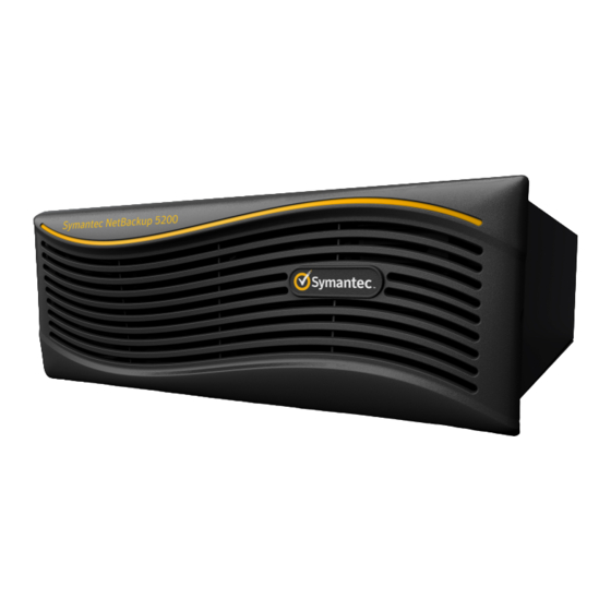
NetBackup 5200. Figure 1-1 NetBackup 5200 appearance The height, width, and depth of the NetBackup 5200 are respectively 175 mm, 446 mm, 685 mm. It can be installed in a standard 19-inch cabinet or in a cabinet with a depth of 1,000 mm (or larger). -
Page 13: Hardware Structure
Video Graphics Array e: Universal Serial Bus f: Gigabit Ethernet 1.3 Hardware Structure This section describes the hardware structure of the NetBackup 5200. The NetBackup 5200 can be configured in two modes, as shown in Table 1-2. Issue 02 (2011-03-28) Symantec Corporation... -
Page 14: Table 1-2 The Parts Of The Netbackup 5200
NetBackup 5200 1 Product Introduction Product Description Table 1-2 The parts of the NetBackup 5200 Configuration mode 1 Configuration mode 2 Chassis Chassis Disk module Disk module Power module Power module Backplane Backplane Fan module Fan module Mainboard Mainboard RAID (Redundant array of independent... -
Page 15: Figure 1-2 Overall Hardware Structure Of The Netbackup 5200
NetBackup 5200 Product Description 1 Product Introduction Figure 1-2 Overall hardware structure of the NetBackup 5200 Disk module Backplane Chassis Power module Fan module Mainboard Figure 1-3 shows the four PCI-E slots resides on the mainboard when configuration mode 1 is employed. -
Page 16: Panel
Slot 0: RAID card Slot 2: 8Gb FC HBA Slot 1: 8Gb FC HBA Slot 3: 8Gb FC HBA 1.4 Panel This section describes the front panel, rear panel, ports, and indicators of the NetBackup 5200. Symantec Corporation Issue 02 (2011-03-28) -
Page 17: Front Panel
NetBackup 5200 Product Description 1 Product Introduction 1.4.1 Front Panel This section describes the front panel of the NetBackup 5200. 1.4.2 Rear Panel This section describes the rear view of the NetBackup 5200. 1.4.1 Front Panel This section describes the front panel of the NetBackup 5200. -
Page 18: Rear Panel
A location command is sent through the management system. From bottom to top and right to left, the 24 slots of the NetBackup 5200 are numbered from a to x, with the bottom right one numbered a. The slot number a, b, c...v, w, or x correspond to the slot number 0, 1, 2...21, 22, or 23. -
Page 19: Figure 1-7 Rear View Of The Netbackup 5200
NetBackup 5200 Product Description 1 Product Introduction Configuration Mode 1 Figure 1-7 shows the rear view of the NetBackup 5200. Figure 1-7 Rear view of the NetBackup 5200 PORT 1 PORT 2 PORT 1 PORT 1 PORT 2 PORT 2... -
Page 20: Figure 1-8 Ports Of The Netbackup 5200
NetBackup 5200 1 Product Introduction Product Description Figure 1-8 Ports of the NetBackup 5200 PORT 1 PORT 2 8Gb FC port Service network port (NIC 2) 10GE service network port or GE service VGA port network port IPMI management network port... -
Page 21: Table 1-5 Description Of The Indicators Of The Netbackup 5200
8Gb FC port SFP+ Connects to a tape library. Connects to the backup network. Table 1-5 lists the indicators of the rear view. Table 1-5 Description of the indicators of the NetBackup 5200 Location Type Color Status Description Power Green The AC power is normal. -
Page 22: Table 1-6 Description Of Indicators On The 10Ge Nic
NetBackup 5200 1 Product Introduction Product Description Table 1-6 Description of indicators on the 10GE NIC Type Color Status Description Green Blinking The link is normal and data is being transferred. ACT/LNK Green The link is normal. No link. No link. -
Page 23: Figure 1-9 Rear View Of The Netbackup 5200
4/Green 2/Amber Description Blinking alternately Firmware error. Configuration Mode 2 Figure 1-9 shows the rear view of the NetBackup 5200. Figure 1-9 Rear view of the NetBackup 5200 PORT 1 PORT 1 PORT 1 PORT 2 PORT 2 PORT 2... -
Page 24: Figure 1-10 Ports Of The Netbackup 5200
Serial port IPMI management network port USB 2.0 port Service network port (NIC 1) Table 1-9 lists the ports on the NetBackup 5200. Table 1-9 Description of the ports on the NetBackup 5200 Name Quantity Model Function USB 2.0 port Connects the mouse, keyboard, and other USB 2.0 devices. -
Page 25: Features
Table 1-8 lists the indicators of the 8Gb FC HBA. NOTE When the NetBackup 5200 is configured with only one power module, the power module is installed in position 18 in Figure 1-7 and position 19 in Figure 1-9. -
Page 26: Technical Specifications
Keyboard Video Mouse e: Dynamic Host Configuration Protocol f: Simple Network Management Protocol 1.6 Technical Specifications This section describes the technical specifications of the NetBackup 5200. Table 1-11 lists the technical specifications of the NetBackup 5200. 1-16 Symantec Corporation... -
Page 27: Environmental Requirements
The maximum weight refers to the weight of the NetBackup 5200 with twenty-four disk modules, two power modules, eight memory modules, RAID card and 8Gb FC HBA. b: The transportation weight is the sum of the maximum weight of the NetBackup 5200 and the maximum weight of the transportation materials. - Page 28 C to 35°C. When the altitude ranges from 1,800 m to 3,000 m, the environment temperature decreases by 0.6°C every time the altitude increases by 100 m. b: The maximum noise of the NetBackup 5200 when the ambient temperature is 25°C. 1.8 Standards Compliant and Certificates This section describes the standards that the NetBackup 5200 complies with and the certificates that the NetBackup 5200 has obtained.
-
Page 29: Table 1-15 Industry Standards
EMC Directive 2004/108/EC European EMC standard EN 55024: 1998+A1+A2 European safety directive LVD Directive 2006/95/EC Industry Standards Table 1-15 lists the industry standards that the NetBackup 5200 complies with. Table 1-15 Industry standards Name Standard No. Ethernet standard IEEE 802.3 FE standard IEEE 802.3u... -
Page 30: Table 1-16 Certificates
NetBackup 5200 1 Product Introduction Product Description Table 1-16 Certificates Name Description The IEC System for Conformity Testing to Standards for Safety of Electrical Equipment (referred to as the IECEE) is based on the use of specific IEC standards for electrical equipment. The CB Scheme is applicable to electrical equipment within the scope of IEC standards for safety, accepted for use in the IECEE. -
Page 31: Product Components
NetBackup 5200 Product Description 2 Product Components Product Components About This Chapter This section describes the features, operating principles, and technical specifications of the NetBackup 5200. 2.1 Chassis This section describes the appearance, features, and technical specifications of the chassis. -
Page 32: Chassis
2.2 Disk Module This section describes the appearance, features, and technical specifications of the disk module. Appearance The NetBackup 5200 supports 24 SATA disks. A SATA disk module consists of the disk handle, disk tray, SATA disk, and SATA convertor. Symantec Corporation... -
Page 33: Figure 2-2 Disk Module
The disk module has the following features: Accommodates the OS The OS of the NetBackup 5200 is installed on the system disks, disks in slot a and slot b. Figure 1-6 shows the location of slot a and slot b. -
Page 34: Power Module
Features The power module provides power for the NetBackup 5200. There are two AC power module slots at the back of the NetBackup 5200 chassis. The power modules support hot swapping. A fault on one power module does not affect the normal running of the NetBackup 5200. -
Page 35: Backplane
NetBackup 5200 Product Description 2 Product Components Table 2-1 Technical specifications Parameter Parameter Value Category Input features Input voltage range 90 V to 264 V Rated input voltage 100 V to 127 V/200 V to 240 V Maximum input current ≤... -
Page 36: Figure 2-4 Front View
NetBackup 5200 2 Product Components Product Description Figure 2-4 Front view Figure 2-5 shows the rear view of the backplane. Figure 2-5 Rear view SAS connector Mini SAS port Backplane power supply port Sideband signal port Features The backplane: Symantec Corporation... -
Page 37: Fan Module
NetBackup 5200 Product Description 2 Product Components Connects to 24 disks through the SAS connectors. Provides signal channels and power for 24 disks. Port Description Table 2-2 lists the ports on the backplane. Table 2-2 Port description Port Function SAS port Connects to a SATA disk. -
Page 38: Figure 2-7 Location Of The Fan Module And Fan Indicators
Product Description Figure 2-7 Location of the fan module and fan indicators Features The fan module dissipates heat for the NetBackup 5200. Fans automatically regulate speed according to internal ambient temperature. CAUTION Faults on any fan will decrease the maximum ambient temperature that the device can tolerate. -
Page 39: Mainboard
NetBackup 5200 Product Description 2 Product Components Parameter Category Parameter Value Rated power 21 W Maximum power ≤30 W Rated rotational speed 10000 r/min Rotational speed control mode Speed adjustment mode Speed adjustment voltage DC -0.8 V to +20 V... -
Page 40: Figure 2-8 Appearance Of The Mainboard
NOTE The inband channel management uses a service channel to manage the NetBackup 5200, such as the service network port; the out-of-band channel management uses the management channel to manage the NetBackup 5200, such as the management network port. -
Page 41: Raid Card
NetBackup 5200 Product Description 2 Product Components Interface Description Table 1-4 describes the interfaces on the mainboard. 2.7 RAID Card This section describes the appearance and features of the RAID card. The RAID card is plugged in the PCI-E x8 slot and used for expanding the eight SAS ports on the mainboard by connecting the two internal Mini SAS cables to the two Mini SAS ports on the backplane. -
Page 42: Figure 2-10 10Ge Nic
NetBackup 5200 2 Product Components Product Description Appearance Figure 2-10 shows the 10GE NIC. Figure 2-10 10GE NIC Table 2-4 lists the indicators on the 10GE NIC. Table 2-4 Description of indicators on the 10GE NIC Type Color Status Description... -
Page 43: Ge Nic (Configuration Mode 1)
NetBackup 5200 Product Description 2 Product Components Technical Specification Table 2-6 lists the technical specifications of the 10GE NIC. Table 2-6 Technical specifications of the 10GE NIC Item Index Dimensions 5.73 inches long, measured without PCI-E bracket Typical power Maximum power: 10.7 W... -
Page 44: 8Gb Fc Hba
NetBackup 5200 2 Product Components Product Description Table 2-7 Description of indicators on the 4-port GE NIC Type Color Status Description Green Blinking The link is normal and data is being transferred. Green The link is normal. No link. Data is being transferred at a rate of 10 Mbit/s. -
Page 45: Figure 2-12 8Gb Fc Hba
NOTE The 8GB FC HBA in slot 3 can provide two tape out FC ports, by using the tape out card (Fibre Channel), data can be exported from the NetBackup 5200 to a tape library for offline storage. Appearance Figure 2-12 shows the 8Gb FC HBA. -
Page 46: Table 2-11 Description Of Ports On 8Gb Fc Hba
NetBackup 5200 2 Product Components Product Description Table 2-11 Description of ports on 8Gb FC HBA Property Value Connectors Dual 8Gbps Fibre Channel Port cables SFP+ with LC-style connector Technical Specification Table 2-12 lists the technical specifications of the 8Gb FC HBA. -
Page 47: Device Cable
3.1 Power Cable and Grounding Cable This section describes the structure, cable connection list, and technical specifications of the power cables and grounding cables used in the NetBackup 5200. 3.2 Signal Cable This section describes the structure, cable connection list, and technical specifications of the external signal cables used in the NetBackup 5200. -
Page 48: Power Cable And Grounding Cable
Each AC power module of the NetBackup 5200 is configured with one AC power cable. One end of the AC power cable is connected to the power socket of the NetBackup 5200, and the other end is connected to the external power supply to provide power for the NetBackup 5200. -
Page 49: Figure 3-1 Structure Of The Ac Power Cable
NetBackup 5200 Product Description 3 Device Cable Figure 3-1 Structure of the AC power cable Main Label (M) 3000 15.8 120° 120° 10.3 AC power connector compliant with the international standard AC power connector compliant with the international standard A power cable includes live line, neutral line, and grounding line, respectively as shown in L,... -
Page 50: Grounding Cable
This section describes the structure, cable connection list, and technical specifications of the grounding cable. The NetBackup 5200 is configured with one grounding cable. One end of the cable connects to the grounding clip of the NetBackup 5200, and the other end connects to the grounding terminal of the NetBackup 5200 cabinet to ensure the safe operation of the NetBackup 5200. -
Page 51: Signal Cable
The NetBackup 5200 communicates with the outside through a network cable. One end of the network cable connects to the management network port or service network port of the NetBackup 5200, and the other end connects to the network switch or the AS. Both ends of the cable are RJ-45 connectors. -
Page 52: Multi-Mode Fiber
This section describes the structure and technical specifications of the multi-mode fiber. The NetBackup 5200 communicates with the FC switch through a multi-mode fiber. One end of the multi-mode fiber connects to the 10GE service network port or FC port , and the other end connects to the FC switch or the tape library. -
Page 53: Serial Cable
Network port connector The network port connector end of the serial cable connects to the system serial port of the NetBackup 5200, and the cable connector end connects to the system serial port of the maintenance terminal. Issue 02 (2011-03-28) - Page 54 NetBackup 5200 3 Device Cable Product Description Cable Connection List Table 3-7 lists the cable connection list of the serial cable. Table 3-7 Cable connection list of the serial cable Connector X1 Connector X2 X1.2 X2.3 X1.3 X2.6 X1.5 X2.5...
- Page 55 NetBackup 5200 Product Description A Abbreviations and Acronyms Abbreviations and Acronyms This section describes acronyms and abbreviations referred to in this document. Alternating Current Battery Backup Unit BIOS Basic Input/Output System Baseboard Management Controller China Compulsory Certification Conformite Europeenne Central Processing Unit...
- Page 56 NetBackup 5200 A Abbreviations and Acronyms Product Description Gigabit Ethernet Host Bus Adapter Inter-Integrated Circuit IOAT Input/Output Acceleration Technology IPMI Intelligent Platform Management Interface Keyboard Video Mouse Lucent Connector MTBF Mean Time Between Failures MTTR Mean Time To Repair Network Interface Card...
- Page 57 NetBackup 5200 Product Description A Abbreviations and Acronyms Serial Attached SCSI SATA Serial Advanced Technology Attachment SNMP Simple Network Management Protocol Total Cost of Ownership Underwriters Laboratories Universal Serial Bus Video Graphics Array Issue 02 (2011-03-28) Symantec Corporation...