Siemens ARCADIS Orbic Quick Manual
Hide thumbs
Also See for ARCADIS Orbic:
- Installation and startup (46 pages) ,
- Installation and startup manual (16 pages) ,
- Manual (34 pages)
Table of Contents
Advertisement
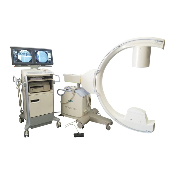
ARCADIS Orbic
ARCADIS Orbic 3D
VB 13C
Quick Guide
C-arm keyboard
top/lateral row of keys
Radiation indicator
Tube unit
temperature
Lift/lower
C-arm
Rotate image
Single-tank
laser light localizer
bottom row of keys
Operating modes:
- Pulsed
fluoroscopy
- Continuous
fluoroscopy
Power Mode
mA
Noise reduction
Open/close
iris diaphragm
Open/close
slot diaphragm
Enlarge stored
images
Contrast
A
B
adjustment left/
right monitor
Read images from
B
B
memory forward/
backward
System OFF
System ON
Reduce/enlarge kV
and mA
Reset fluoroscopy
time
Switch dose stop
function on/off
Operating modes:
ROAD
SUB
- Subtraction
MAP
- Roadmap
- Digital
DR
radiography
Enlarge live image
Image reversal
R
R
left/right or
top/bottom
Rotate slot
diaphragm
Edge
enhancement
Monitor split
horizontal/vertical
Save image
A B
Print image
PRINT
Advertisement
Table of Contents

Related Manuals for Siemens ARCADIS Orbic


Summary of Contents for Siemens ARCADIS Orbic
- Page 1 Reset fluoroscopy time Single-tank Switch dose stop laser light localizer function on/off bottom row of keys ARCADIS Orbic Operating modes: Operating modes: ARCADIS Orbic 3D ROAD - Pulsed - Subtraction fluoroscopy - Roadmap - Continuous - Digital fluoroscopy radiography VB 13C...
- Page 2 Monitor trolley symbol keypad Brightness – Brightness + Contrast – Contrast + Scroll study back Scroll study forward Scroll series back Scroll series forward Scroll image back Scroll image forward Switch between Send to network negative and node 1 positive image This product is provided with a CE marking in accordance with the regulations stated in Directive 93/42/EEC of June 14th, 1993...
- Page 3 ARCADIS Orbic/Orbic 3D from startup through to shutdown of the sys- tem including optional functions such as con- nection to a hospital network or subtraction. More detailed and complete descriptions can be found in the ARCADIS Orbic/Orbic 3D Operator Manual.
-
Page 4: Table Of Contents
Table of Contents Basics Input devices........7 syngo user interface......9 syngo control elements ...... 11 Product Overview C-arm system ........13 Monitor trolley ........17 Examination Procedure Preparing the system ......19 Patient registration ......21 Preparation in the Examination task card ...... - Page 5 3D option Overview ..........65 3D scan ..........67 3D view ..........71 New 3D ranges ........75 Saving, filming, transferring ....79 3D display modes ......81 3D Image Fusion (Option) ....85 Documentation Printing ..........93 Burning CDs ........103 Reports Generating reports ......
- Page 6 Basics This chapter is addressed to syngo begin- ners and users with little computer experi- ence. Functions of the symbol keypad see fold- out cover.
-
Page 7: Basics
Basics This chapter provides you with basic informa- tion on the input devices of the computer at the monitor trolley and on the syngo user interface. Input devices The mouse (1) Left button Single click: select/mark Double click: load data/program Button kept pressed: drag/move (2) Middle button Button kept pressed: windowing... - Page 8 Basics After the ARCADIS Orbic/Orbic 3D system has been switched on, the syngo user interface automatically appears on the monitor trolley screens.
-
Page 9: Syngo User Interface
Basics syngo user interface syngo consists of several stacked task cards. These are assigned to the individual steps of the workflow. Task cards (1) Menu bar Calling up of main menus and submenus (2) Tabs Selection/switching of task cards (3) Stack of subtask cards Selection of processing tools and display functions Switching of subtask card via tab... - Page 10 Basics (10)
-
Page 11: Syngo Control Elements
Basics syngo control elements Control elements on the screen are easiest selected with the mouse. Menus (1) Main menu Opens by pressing left mouse button (2) Popup menu Opens by pressing right mouse button The content depends on the mouse posi- tion ("mouse focus") on the screen Input elements (3) Text input field... -
Page 12: Product Overview
Product Overview As soon as you press the emergency stop button, motorized up and down movement of the C-arm system is disabled. -
Page 13: C-Arm System
Product Overview C-arm system C-arm (1) Image intensifier (2) X-ray tube (3) Emergency stop (4) Hand switch (5) Steering lever (6) Holder for footswitch (7) Locking brake Steering lever, brakes (5) Steering lever ❏ Steering lever straight: Move C-arm system in any direction ❏... - Page 14 Product Overview...
- Page 15 Product Overview Moving the C-arm system (1) Vertical travel (motorized) Lift and lower C-arm up to 40 cm (2) Orbital movement Change between a.p. and lateral position ➭ Starting from the a.p. position, C-arm swivels by 95° in both directions, 190° in total.
- Page 16 Product Overview Description of keyboard see Basics chap- ter.
-
Page 17: Monitor Trolley
Product Overview Monitor trolley (1) TFT flat screen monitors (2) Keyboard (3) Power on/off switch (4) CD drive (5) Direction locks on the back wheels (6) Brakes on the front wheels... -
Page 18: Examination Procedure
Examination Procedure If an additional access control mechanism is configured for the system, you have to log in with your name and password. -
Page 19: Preparing The System
Examination Procedure Preparing the system Connecting, switching on and booting ✧ Connect the monitor trolley connecting cable to the C-arm system (1). ✧ If available, connect the network cable (if the system is connected to an informa- tion system or a navigation system or net- work printer) (2). - Page 20 Examination Procedure During operation, the window can be opened by pressing the Patient Registration icon button on the monitor trolley.
-
Page 21: Patient Registration
Examination Procedure Patient registration First, the Patient Registration window (1) appears directly. (Here: maximal configuration) ✧ Enter the patient data into this mask (1). At a minimum, the bold fields must be filled out. Using the mouse, click on the Exam (2) ✧... - Page 22 Examination Procedure To select parameters, use the mouse to click the monitor trolley. If the optional laser light localizer is avail- able, the object should be positioned with the laser light localizer, i.e. without radia- tion, as far as possible for reasons of radia- tion protection.
-
Page 23: Preparation In The Examination Task Card
Examination Procedure Preparation in the Examination task card ✧ Select the medical application area (1). ✧ Select the body region by clicking the VPA (Virtual Patient Anatomy) (2). ✧ Select the required application program (3). ➭ With the application program you simulta- neously select a dose level (reduced, standard, increased). - Page 24 Examination Procedure Exception: If the continuous fluoroscopy mode is set, pressing the left footswitch releases a single exposure.
-
Page 25: Radiation Release And Dose Display
Examination Procedure Radiation release and dose display Radiation release with the footswitch ✧ Actuate the right footswitch to release continuous fluoroscopy (1). ✧ Actuate the left footswitch to release the set operating mode (2). Radiation release with the hand switch ✧... - Page 26 Examination Procedure ADR stop is recommended, for example, for ❏ thin objects, e.g. wrist (the movement causes the object to slide out of the central beam, the image is underex- posed), ❏ metal (high density of the metal leads to strong overexposure), ❏...
- Page 27 Examination Procedure Radiation time and dose display (1) Display of accumulated fluoroscopic time at the C-arm system (2) Display of accumulated fluoroscopic time at the monitor trolley (Examination task card) (3) Display of accumulated dose at the moni- tor trolley (with optional dose measuring chamber) Alternative: Display of air kerma values (preceding item: accumulated air kerma).
- Page 28 Examination Procedure...
-
Page 29: High-Contrast Fluoroscopy (Power Mode)
Examination Procedure High-contrast fluoroscopy (Power Mode) Power Mode is an additional function that can be selected for the fluoroscopy mode. With Power Mode a higher contrast is achieved, but with a higher dose. Select the Power Mode function at the ✧... - Page 30 Examination Procedure The rotation is performed without radiation and can be observed on the monitor.
-
Page 31: Image Rotation And Reversal
Examination Procedure Image rotation and reversal At the C-arm system Press one of the image rotation buttons ✧ for the required direction of rotation (1). ➭ The angle of rotation in relation to the starting position is shown (2). Press one of the image reversal buttons to ✧... - Page 32 Examination Procedure...
-
Page 33: Collimator Setting
Examination Procedure Collimator setting For radiation protection reasons collimators should be inserted. These can be set at the C-arm system. (1) Moves the iris diaphragm into/out of the beam path (2) Rotates the semitransparent diaphragm (3) Moves the semitransparent diaphragm into/out of the beam path The iris diaphragm is a multileaf collimator used for concentric collimation of the radia-... - Page 34 Examination Procedure (1) (2)
-
Page 35: Changing The Contrast
Examination Procedure Changing the contrast If the image quality is insufficient, a different gray-level curve can be selected at the control panel of the C-arm system during the exami- nation to change the contrast of the image (and all further images). In addition, the edge enhancement of the live images can be changed. - Page 36 Examination Procedure At the end of radiation, the image last acquired is displayed (LIH, Last Image Hold). If radiation is released again, the LIH image is overwritten.
-
Page 37: Saving Images
Examination Procedure Saving images Single exposure In this operating mode the generated images are automatically saved in the local database of the Patient Browser. Fluoroscopy, pulsed fluoroscopy, subtraction, Roadmap In these operating modes images are stored in the temporary image memory and over- written by new images. - Page 38 Examination Procedure If Autoloop (option) is configured in the exam set used, review of the scene is started automatically at the end of radia- tion. You can load the scene into the Viewing task card at any time and review it there. If the MPPS option is installed, the Modality Performed Procedure Step window for per- formance documentation is now displayed.
-
Page 39: Fluoro Loop/Lsh (Option)
Examination Procedure Fluoro Loop/LSH (option) In the fluoroscopy, subtraction and Roadmap modes, scenes can be reviewed and stored (Last Scene Hold) during the examination. Reviewing a scene After radiation is ended, the buttons for con- trolling the scene review are displayed. (1) Start (2) Stop (3) Previous frame... -
Page 40: Subtraction And Roadmap
Subtraction and Roadmap The Subtraction and Roadmap modes are an option for C-arms used in cardiac and vascular surgery. -
Page 41: Performing A Subtraction Scene
Subtraction and Roadmap Performing a subtraction scene Contrast medium injected into the vessels helps to show vessels and changes of/in these vessels (e.g. aneurysms, ruptures). Procedure ✧ Prepare the examination in the Examination task card: (1) Selection of the required application pro- gram (2) Selection of the Subtraction mode ✧... - Page 42 Subtraction and Roadmap If auto store is activated in the configura- tion menu, the images of a subtraction scene are automatically saved in the local database. They can then be retrieved for postprocessing at the end of the examina- tion.
-
Page 43: Postprocessing A Subtraction Scene
Subtraction and Roadmap Postprocessing a subtraction scene ✧ First, load the subtraction scene from the Patient Browser into the Viewing task card. Pixelshift Pixelshift allows you to make the mask and fluoroscopy image coincide. This function is used if the position of the patient has changed in the course of the series in relation to the position of the mask. - Page 44 Subtraction and Roadmap...
- Page 45 Subtraction and Roadmap Auto Pixelshift This function allows automatic pixelshift for a selected region. Click the Auto Pixelshift button (1). ✧ ➭ The mouse pointer changes into a square. ✧ Move the square to the area in the image where the misalignment can clearly be seen.
- Page 46 Subtraction and Roadmap...
- Page 47 Subtraction and Roadmap Dual channel function With this function the entire series is dis- played unsubtracted during postprocessing in the Native task card (on the right-hand moni- tor). At the same time, the subtracted display is shown in the Viewing task card (on the left- hand monitor).
- Page 48 Subtraction and Roadmap (2) (3) (4) (5) (6) (7)
- Page 49 Subtraction and Roadmap Landmark The Landmark function allows you to subse- quently add an anatomical background for ori- entation purposes (0 to 30 %). ✧ Keeping the left mouse button pressed, drag the bar to the required value (1). Movie mode The replay of the subtraction scene can be repeated in the Viewing task card.
- Page 50 Subtraction and Roadmap During catheter placement the images are not automatically stored. To manually save images, use the save but- ton on the hand switch or C-arm system. It is not necessary to create a subtraction scene if the Roadmap exam connects to a subtraction angiography.
-
Page 51: Roadmap
Subtraction and Roadmap Roadmap The Roadmap mode is also used in vascular surgery. This mode is used to place catheters in vessels under fluoroscopy. The examination comprises the following steps: Generation of a subtraction scene ✧ Select the Roadmap operating mode in the Examination task card. -
Page 52: Postprocessing
Postprocessing 2D images are postprocessed in the Viewing task card. -
Page 53: Loading Patient Images Into The Viewing Task Card
Postprocessing Loading patient images into the Viewing task card Open the Viewing task card. ✧ Open the Patient Browser with the Call ✧ up Patient Browser button on the moni- tor trolley (1). Load the required series into the Viewing ✧... - Page 54 Postprocessing...
-
Page 55: Image Display
Postprocessing Image display In the View subtask card you can choose between different monitor layouts. (1) Different screen divisions (2) Hiding graphics and patient data in the image area (3) Stripe display: the images are arranged next to each other (4) Stack display: the individual images are arranged one on top of the other... - Page 56 Postprocessing...
-
Page 57: Measuring And Annotations
Postprocessing Measuring and annotations In the Tools subtask card images can be mea- sured and annotations can be added. (1) Diaphragms The subsequent simulation of diaphragms improves the visualization of fine struc- tures that are difficult to see in the image (2) Magnifying glass Individual areas of the loaded image are shown enlarged... - Page 58 Postprocessing Distances cannot be measured directly in the images, since the position of the object in the beam path and thus the magnification effect is not clear. A calibration must be performed first before a distance can be clearly determined. The calibration object must be perpendicular to the central ray in the area of the structure to be measured (generally in the center of...
- Page 59 Postprocessing Calibrating and measuring distances ❏ Calibrating (1st step) Activate the calibration function by click- ✧ ing the corresponding button (1). ➭ A green line appears in the image area which can be lengthened, shortened and positioned as desired with the mouse (2). ✧...
- Page 60 Postprocessing Edge enhancement (3) means artificially increasing the difference between two gray levels.
-
Page 61: Image Manipulation
Postprocessing Image manipulation Images can be postprocessed in the Image subtask card. ✧ Prior to postprocessing, activate the required function by clicking the corre- sponding button: (1) Change of contrast The contrast is changed in four defined steps (2) Image rotation Rotation with the left mouse button pressed (3) Edge enhancement... - Page 62 Postprocessing Windowing means changing the gray levels in an image and thus the brightness (center of the grayscale) and contrast (width of the grayscale) of the image.
- Page 63 Postprocessing Windowing ❏ With buttons/softkeys ✧ Select the preset contrast levels by click- → ing the buttons ( Page 61). ❏ With the keyboard of the monitor trolley ✧ Select the brightness and contrast step by step (1). ❏ With the mouse on the monitor trolley ✧...
- Page 64 3D option Regular calibration of the system is an important requirement to ensure good image quality of the 3D scans.
-
Page 65: Option Overview
3D option Overview The 3D option consists essentially of motor control of the orbital movement which can be switched in optionally and a task card for 3D image reconstruction and visualization. Areas of application The 3D option is suitable for intraoperative use in the following areas: ❏... - Page 66 3D option...
-
Page 67: 3D Scan
3D option 3D scan The 3D application comprises the following steps: Adjustment Adjustment with the I.I. laser aimer is per- formed in two C-arm positions. (1) Horizontal (2) Vertical - 90° ✧ Bring the object to be examined into the isocenter. - Page 68 3D option After the test run you must not change the position of the C-arm or change any set- tings of the entire unit.
- Page 69 3D option Test run (collision monitoring) ✧ Start the test run by clicking the button in the Acquisition dialog box (1). The Collision check dialog is displayed. ➭ This dialog informs you of the state of the test run and guides you through the pro- cedure: (2) Currently required procedure step (3) Upcoming procedure steps...
- Page 70 3D option Showing/hiding the cross-hair by clicking this button. Return to the three standard views by clicking this button.
-
Page 71: 3D View
3D option 3D view In the 3D task card, a series (range) of two- dimensional slice images is reconstructed from the scanned 3D volume (MPR = [Multi- planar Reconstruction] display mode). 3D task card The MPR series is displayed in the reference segments in the three standard views. - Page 72 3D option Ortho Sync is used, for example, to display slices along the main axis of a bone.
- Page 73 3D option Moving a cut plane ✧ Use the dog ears to scroll forward or back- ward slice by slice in a segment (1). ✧ Move a reference line with the mouse to display the new slice position in the rele- vant segment (2).
- Page 74 3D option You can also outline subareas by drawing a curved cut line and then display this cut as a slice image. You can change the settings with the mouse (moving the start/end line in the reference segment). If the dis- tance between images is to remain con- stant, the Constant number of images function must be deactivated.
-
Page 75: New 3D Ranges
3D option New 3D ranges The Settings subtask card allows you to reconstruct new cut planes based on any ref- erence image. (1) Range of parallel tomographic images (2) Range of radial tomographic images (3) Expanded range ✧ First, select the reference image with the required original view. - Page 76 3D option Note that with curved cuts no orientation aids are displayed in the image. The per- forming physician is responsible for the pro- fessional and correct interpretation of the reconstructed image.
- Page 77 3D option Generating radial images Click on the Radial Ranges button (1). ✧ In the Radial Ranges dialog, enter the ✧ image thickness, angle between images and number of images (2). Click Start. ✧ ➭ The new range is shown in the output segment.
- Page 78 3D option Selection of the entire image stack with the Edit > Select series menu.
-
Page 79: Saving, Filming, Transferring
3D option Saving, filming, transferring ✧ First, click the image to be processed. Saving quickly The new images are saved in the currently loaded series under the relevant patient name. To do this, click the Save button (1). ✧ Saving in a new series The new images are saved as a new series with the relevant patient name. - Page 80 3D option The display mode can be changed in any reference segment at any time. To reset the standard display mode, click the MPR button.
-
Page 81: 3D Display Modes
3D option 3D display modes From the MPR standard display you can switch to the following display modes for the scanned volume: ❏ MPR Thick Images with adjustable slice thickness ❏ SSD (Shaded Surface Display) Three-dimensional surface reconstruction ✧ First, click the segment for which you want to change the output type. - Page 82 3D option...
- Page 83 3D option Changing the SSD threshold If necessary, the preset threshold values for the surface reconstruction can be changed individually. Click the SSD button (1) with the right ✧ mouse button. The display of the 3D card is reset for opti- ➭...
- Page 84 3D option You need two volume data sets for a fusion evaluation: the reference series serves as the anchor point for superimposing, the model series is spatially aligned with the reference series. Both image series should cover approxi- mately the same exam region.
-
Page 85: Image Fusion (Option)
3D option 3D Image Fusion (Option) The Fusion function allows you to combine the results of different acquisition techniques or images acquired at different times by superimposing them. Load image datasets. Select the reference series in the Patient ✧ Browser. Click the 3D MPR button (1). - Page 86 3D option You can alternate orientation modes or run several one after the other until you have the optimal superimposition. Use this button to save the interim results and the final results of the orientation. You can return to this orienta- tion (user-defined) at any time using the Registration Matrix selection list.
- Page 87 3D option Start orientation of image series ✧ If it is not already displayed, open the Fusion Registration dialog using this button (1). ✧ Select a registration matrix (2): ❏ Default if there is no suitable default orientation ❏ User-defined if a suitable orientation has already been saved as a matrix ✧...
- Page 88 3D option (10)
- Page 89 3D option Aligning the landmarks (optional) ✧ Holding down the left mouse button, posi- tion the cross-hair on a marked point (1) in the reference segments (left). ✧ Mark the same position in the model series (right) (2). Click Add (3). ✧...
- Page 90 3D option...
- Page 91 3D option Apply superimposition Click OK to close the superimposition (1). ✧ ➭ The registration matrix with the superim- position data is saved as a data object in the reference series. Show superimposed images Change the display using the Image subtask card: (2) Side-by-Side The reference images are shown on the...
-
Page 92: Documentation
Documentation In radiology the terms "filming" (= printing process), "camera" (= output device) and "exposing" (= printing) are used for the printing of patient images. The syngo user interface uses correspond- ing terms. -
Page 93: Printing
Documentation Printing If the printing function is configured, the Filming task card additionally appears on the right monitor. Here, the images to be printed are collected in film sheets, processed if necessary, and then sent to the printer as a film job. Procedure (1) Copying images to the film sheet: –... - Page 94 Documentation...
- Page 95 Documentation Copying images to the film sheet from the Viewing task card Print jobs can be created in the Viewing task card in parallel with image postprocessing. ✧ Click the patient image to be copied to the film sheet (1). Then click Copy to Film Sheet (2).
- Page 96 Documentation...
- Page 97 Documentation Checking the film job and printing from the film preview Click the Film Preview button in the ✧ Patient Browser (1). ➭ A dialog box is opened which shows dif- ferent functions for the film sheet: (2) Dog ears for scrolling through the film sheets (3) Patient name (4) Setting the number of copies of a film job...
- Page 98 Documentation...
- Page 99 Documentation Editing the film sheet in the Filming task card Click the Filming task card on the right ✧ monitor (1). ❏ Layout ✧ Select the required film layout in the Layout subtask card (2). ❏ Image display On the Images subtask card, select the ✧...
- Page 100 Documentation (10)
- Page 101 Documentation ❏ Camera/printer setting In the Camera subtask card, select a dif- ✧ ferent camera/printer or film size, if nec- essary: (1) Select the camera if several cameras are configured (2) Display of the film job status, e.g. "queued", "printed" etc. (3) Select one of the film formats available in the camera ❏...
- Page 102 Documentation Only non-rewritable CDs, (CD-Rs), can be used. Rewritable CDs (CD-RWs) are not accepted. The DICOM viewer is started directly from the CD; no files are installed on the com- puter.
-
Page 103: Burning Cds
Documentation Burning CDs As your system is configured for multi-ses- sion, you can store your data to unrecorded CD-Rs, or CD-Rs that have already been writ- ten to. The new data is added to the old data on the CD-R. ❏... -
Page 104: Reports
Reports The prerequisite for both report types is the registration and examination of a patient. In addition, for a LithoReport, the lithotripsy function must be enabled on your system and connected to the imaging system. The radiation summary report is generated automatically based on the present exami- nation data. -
Page 105: Generating Reports
Reports Generating reports If the reporting function is enabled on your system, important examination data are auto- matically compiled into a structured report for documentation and treatment purposes. Report types ❏ Radiation summary report contains the accumulated values of the examination for the number of exposures, fluoroscopy time and dose area product ❏... - Page 106 Reports A lithotripsy procedure is possible only after a patient has been registered. When you start an ESWL treatment, the LithoReport editor is opened automatically with the new report. In the Viewing task card you can open reports by clicking the rele- vant button on the Reporting subtask card.
-
Page 107: Editing A Lithoreport
Reports Editing a LithoReport Unlike in the case of the radiation summary report, you can enter or subsequently change part of the LithoReport data yourself. Opening a report ✧ Select the required LithoReport in the Patient Browser and select Reporting > Open report. - Page 108 Reports During an examination the LithoReport edi- tor is automatically in edit mode. To close the LithoReport editor, click OK. With this button in the LithoReport editor you can call up the print pre- view of the report.
-
Page 109: Printing And Exporting A Report
Reports Completing and changing data To modify data, you need to change into edit mode. This is, however, not possible if the report has already been completed (status “completed”). Click Edit (1). ✧ Make your changes in the Patient/ ✧ Diagnosis, Therapy, Summary, Postprocessing cards. - Page 110 Reports Files in pdf format can be read and printed on other computers with the Acrobat Reader freeware program. The program compiles all reports from the local database that meet your specified cri- teria.
- Page 111 Reports Exporting a report as pdf file The report is saved as a pdf file in the CDR_OFFLINE directory. From there you can write the file to CD. Select the required report in the Patient ✧ Browser and call up Reporting > Export Report to..
-
Page 112: Connectivity
Connectivity Monitor trolley Monitor trolley... - Page 113 Connectivity ARCADIS can optionally be connected to a network. The following two variants are avail- able: DICOM System Basic Send/Receive + Storage Commitment, Print (1) Send/Receive Sending and receiving of patient images (2) Storage Commitment Requesting a confirmation that images have been securely stored after sending (3) Print Printing of patient images on X-ray films...
- Page 114 Connectivity You can also receive images from another system (CT, MR etc.) or workstation. For this, the images have to be actively sent from this system or workstation to ARCADIS.
-
Page 115: Send/Storage Commitment
(information system or worksta- tion). Sending to a standard address Press the Send key on the keyboard of ✧ the monitor trolley (4). ➭ The selected patient images are sent to the first "standard" node configured by Siemens Service. - Page 116 Connectivity...
- Page 117 Connectivity Tracking network processes Click the Network Status button (1). ✧ ➭ Current processes in the network are shown (2). Storage Commitment If patient data are sent or archived in an infor- mation system, the Storage Commitment function requests a confirmation from the receiving station that images have been securely stored: (3) Column for error messages...
- Page 118 Connectivity Get Worklist offers the advantage of a sim- plified workflow: In an information system the OR plan (i.e. which patients are planned for a certain operating room or C-arm) can be prepared the day before and retrieved in the OR. Patients can then be retrieved quickly just before the procedure and the data can be transferred to the Examination task card.
-
Page 119: Get Worklist
Connectivity Get Worklist The Get Worklist function contains a request for a worklist within an information system. Double-click the Scheduler in the Patient ✧ Browser (1). ➭ A worklist with patients whose data are present in XA format (data format for con- ventional radiography) appears. - Page 120 Connectivity...
-
Page 121: Mpps - Modality Performed Procedure Step
Connectivity MPPS – Modality Performed Procedure Step MPPS (Modality Performed Procedure Step) is a confirmation to an information system that a certain process (in this case the exam- ination of a patient) has been completed. Calling up MPPS after an examination Select Patient >... - Page 122 Connectivity The Retrieve function is important above all for preoperative images that are needed for virtually any procedure.
-
Page 123: Query/Retrieve
Connectivity Query/Retrieve ❏ Query A query to an information system can be started. If the patient is already known to the information system, the existing images are displayed. ❏ Retrieve Images can be imported into the local database and loaded into the Viewing task card. -
Page 124: Navilink 2D/3D
NaviLink 2D/3D Communication is implemented either directly between the C-arm and the naviga- tion system or through a hospital network. In the first case, the network cable from the C-arm is connected directly to the naviga- tion system. In the second case it is plugged into the network socket in the OR room. -
Page 125: Features
Features NaviLink 2D is a newly developed interface that enables the communication of 2D image data between ARCADIS Orbic and a naviga- tion system. With the exception of the connection of the C-arm to the navigation system via the net-... - Page 126 NaviLink 2D/3D Digital Radiography must be selected as operating mode. The navigation system does not accept images of other operating modes. Confirmation is required only if the image is to be used for navigation. All other images are only stored in the Patient Browser at the monitor trolley.
-
Page 127: Procedure
NaviLink 2D/3D Procedure Preparation ✧ Set up the C-arm and the navigation sys- tem and start both systems. ✧ Enter the patient data. ✧ Establish direct communication with the aid of a network cable. ➭ The readiness of the C-arm is indicated by an icon in the status bar of the Examination task card (1). -
Page 128: Dismantling
Dismantling The C-arm can only be moved while it is switched on. To define the switch-on duration yourself, you can perform a full shut-down manually. To do so, select Options > End session in the main menu before turning the system off. -
Page 129: Transport Position
Dismantling Transport position The C-arm system should be transported and parked in a zero position. ✧ Lower the lifting column fully (1). ✧ Move the C-arm into an a.p. position (2). Switching off ✧ Switch the unit off at the monitor trolley or the C-arm system: (3) Switching off at the monitor trolley (4) Switching off at the C-arm system... - Page 130 Notes...
- Page 131 Siemens reserves the right to modify the design and specifications contained herein without prior notice. Please contact your local Siemens Sales Representative for the most up-to-date information. Note: Original images always lose a certain amount of detail when reproduced.
- Page 132 Siemens AG Wittelsbacher Platz 2 D-80333 München, Germany Contact: Siemens AG, Medical Solutions Special Systems Henkestraße 127 D-91052 Erlangen, Germany 2006 All rights reserved Print No.: SPR2-320.622.01.02.02 Printed in the Federal Republic of Germany Siemens AG 10/06...