Table of Contents
Advertisement
Quick Links
Technical Reference Guide
Safety Precautions
Describes precautions that ensure safe use of the
product. Read this first.
Product Overview
Describes product features.
Setup
Describes product and peripheral device
installation and setup procedures.
Advanced Product Use
Describes advanced product use.
Application Development Information
Provides information required for controlling
this product and application development.
Handling the Product
Describes the basic operating procedures of the
product.
Troubleshooting
Describes what to do when problems occur.
Product Specifications
Provides product specifications, interface
specifications, and character code tables.
M00151600
Rev. A
Advertisement
Table of Contents

Related Manuals for Epson TM-S9000II-NW


Summary of Contents for Epson TM-S9000II-NW
- Page 1 Technical Reference Guide Safety Precautions Describes precautions that ensure safe use of the product. Read this first. Product Overview Describes product features. Setup Describes product and peripheral device installation and setup procedures. Advanced Product Use Describes advanced product use. Application Development Information Provides information required for controlling this product and application development.
- Page 2 • Neither is any liability assumed for damages resulting from the use of the information contained herein. • Neither Seiko Epson Corporation nor its affiliates shall be liable to the purchaser of this product or third par- ties for damages, losses, costs, or expenses incurred by purchaser or third parties as a result of: accident, mis- use, or abuse of this product or unauthorized modifications, repairs, or alterations to this product, or (excluding the U.S.) failure to strictly comply with Seiko Epson Corporation's operating and maintenance...
-
Page 3: Table Of Contents
Table of Contents ■ Safety Precautions ........................7 Meanings of Symbols ............................... 7 Cautions on Installation..............................7 Cautions on Power Supply.............................. 7 Cautions on Handling............................... 8 Cautions on Ink Cartridges ............................. 9 Caution Label..................................10 ■ Restriction of Use ......................... 11 ■ About This Manual....................... 12 Purpose of This Manual..............................12 Manual Organization ..............................12 Product Overview ..................13... - Page 4 Setup .......................34 ■ Setup Flow..........................34 ■ Product Installation ......................35 Removing the Packing Materials..........................35 Installation ..................................35 ■ Connecting a Cash Drawer ....................36 Specifications Required for a Cash Drawer ......................36 Connecting the Drawer Cable .............................37 ■ Connecting a Power Supply....................38 ■...
- Page 5 ■ Driver for Windows Environment..................66 ■ Web API..........................67 ■ ePOS-Print XML ........................68 ■ Utilities ........................... 69 TM-S9000II Utility................................69 Epson Deployment Tool..............................69 BmpToRaster ..................................69 ■ Downloading Software....................... 70 Handling the Product ..................71 ■ Turning On/Off ........................71 Turning the Power On ..............................71 Turning the Power Off ..............................71...
- Page 6 ■ Cut Sheet Jam ........................89 ■ ID Card Does Not Come Out....................90 ■ Roll Paper Jam ........................91 ■ Cannot Open the Roll Paper Cover ................... 92 ■ Problems with Print Quality....................93 Printing on Roll Paper Is Blurred ..........................93 Printing on Cut Sheets Is Blurry ..........................93 ■...
-
Page 7: Safety Precautions
Safety Precautions Meanings of Symbols The symbols explained below are used in this manual. Be sure to take the time to understand the meaning of each symbol before using the product. Handling the product improperly by ignoring this symbol can lead to death or serious injury. WARNING Ignoring this symbol and using the product improperly can lead to the problems listed below. -
Page 8: Cautions On Handling
❏ Contact qualified service personnel for advice if the power cable is damaged. Further- more, observe the following points so as not to damage the power cable. ∗ Do not modify the power cable. WARNING ∗ Do not place heavy objects on the power cable. ∗... -
Page 9: Cautions On Ink Cartridges
❏ Store the ink cartridges in a place out of reach of children. ❏ Epson recommends storing ink cartridges in a cool and dark place. ❏ If you wish to use ink cartridges that have been stored in a cold place for a long period of time, leave them for at least 3 hours in a place that is at room temperature before use. -
Page 10: Caution Label
Caution Label The labels affixed to the product indicate the following cautions. CAUTION: Do not touch the thermal head during or immediately after use. They may be very hot after a print operation. Thermal head... -
Page 11: Restriction Of Use
Restriction of Use When this product is used for applications requiring high reliability/safety such as transportation devices related to aviation, rail, marine, automotive etc.; disaster prevention devices; various safety devices etc.; or func- tional/precision devices etc., you should use this product only after giving consideration to including fail-safes and redundancies into your design to maintain safety and total system reliability. -
Page 12: About This Manual
About This Manual Purpose of This Manual This manual is intended to provide development engineers with information about product functions, opera- tions, maintenance, and troubleshooting, and the information needed for application development and design. Manual Organization This manual is organized as shown below. Chapter 1 Product Overview Chapter 2... -
Page 13: Product Overview
❏ Equipped with an interface selection switch (physical switch) • USB connection (compatible with the API for TM-S9000II-MJ) • Network connection (with built-in Epson Web API ) ❏ Drawer connection allowed ❏ Counter that comes in handy for remote maintenance ❏... -
Page 14: Product Configuration
Chapter 1 Product Overview Product Configuration Functions and accessories for this product depend on the model. Accessories ❏ Roll paper (for initial trial operation) ❏ Special ink cartridge SJIC18(K) x 2 ❏ Dedicated AC adapter; "AC Adapter V" ❏ USB cable (length: 170 cm, color: black) ❏... -
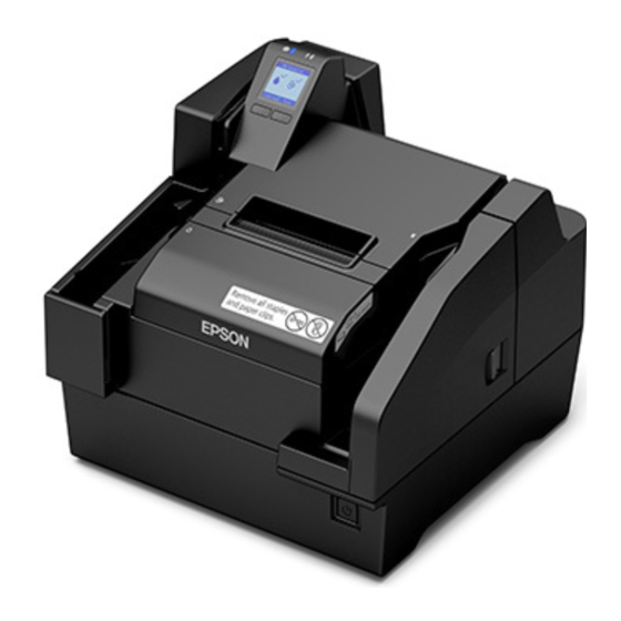
Page 15: Part Names And Functions
Chapter 1 Product Overview Part Names and Functions Front ID card slot To read an ID card, insert it. (“ID Card Processing” on page Main pocket Pockets hold cut sheets ejected after processing. Pocket guides Pull out the pocket guide to match the length of the cut sheets being used. Ink cartridge cover Open this cover to install/replace the ink cartridge. - Page 16 Chapter 1 Product Overview Connector cover Use the printer with this cover attached to protect cables. MICR cover Open this cover if cut sheets become jammed. (“Opening the MICR Cover, Back Cover, and Scanner Cover” on page “Cut Sheet Jam” on page Roll paper cover Open this cover to load or replace the roll paper.
-
Page 17: Operation Panel
Chapter 1 Product Overview Operation Panel (POWER) LED Lights when the product is turned on. Flashes during printing and while ink is charging. (ERROR) LED Lights when an error occurs. (“Checking the Product Status” on page Shows the status of consumables and the product. (“Checking the Product Status”... -
Page 18: Rear
Chapter 1 Product Overview Rear Back cover Open this cover if cut sheets become jammed. (“Opening the MICR Cover, Back Cover, and Scanner Cover” on page “Cut Sheet Jam”) Scanner cover Open this cover if cut sheets or an ID card becomes jammed. (“Opening the MICR Cover, Back Cover, and Scanner Cover”... - Page 19 Chapter 1 Product Overview Ethernet connector Connect a LAN cable. Status sheet button Press this to print a status sheet. (“Printing a Status Sheet (network mode only)” on page...
-
Page 20: Checking The Product Status
Chapter 1 Product Overview Checking the Product Status The status of the product can be checked from a combination of the LEDs lighting/flashing and the LCD dis- play. The error type cannot be distinguished by the LED pattern. Develop an application that reads the status from the application and identifies the error, and lets the user know the required recovery procedure. -
Page 21: Statuses And Errors
Chapter 1 Product Overview LCD display Status An ink cartridge is not installed. An ink cartridge must be loaded to print on cut sheets. There is not enough ink for periodic ink head cleaning. The ink cartridge needs to be replaced to perform cleaning. Statuses and Errors The status of the product can be checked from a combination of the LEDs lighting/flashing and the LCD dis- play. - Page 22 Chapter 1 Product Overview LCD display Product status POWER ERROR The roll paper cover is open Auto cutter position error (“Recoverable Error” on page Ink cover is open One or more of the following covers are open: MICR cover, back cover, scanner cover Standing by for insertion of cut sheets Cut sheet detection...
- Page 23 Chapter 1 Product Overview LCD display Product status POWER ERROR Cartridge loading or replacement required (“Installing the Ink Cartridges” on page Roll paper loading or replacement required (“Loading Roll Paper” on page Ink head cleaning standby (“Ink Head Cleaning” on page Ink head cleaning •...
- Page 24 Chapter 1 Product Overview LCD display Product status POWER ERROR Macro execution function operation standby The pump unit is near the end of it's service life Unrecoverable error (“Unrecoverable Error” on page Insufficient ink for periodic ink head cleaning...
-
Page 25: Network Settings Display Mode
Chapter 1 Product Overview Network Settings Display Mode You can display the network settings on the screen by pressing Button 1 and Button 2 at the same time for two seconds. Network mode (Ethernet) Network mode (Wi-Fi) -
Page 26: Cut Sheet Processing Modes
Chapter 1 Product Overview Cut Sheet Processing Modes There are two modes for processing cut sheets. Select the method most suitable for your environment. • High-speed mode (“High-speed Mode” on page • Confirmation mode (“Confirmation Mode (USB connection only)” on page For details on processing modes, refer to the TM-S9000MJ API Reference Guide. - Page 27 Chapter 1 Product Overview Document Processing Sequence <First cut sheet> Fed from the ASF Check for double feeding MICR reading <Second cut sheet> Ink jet printing Fed from the ASF Capturing image on both sides Check for double feeding Ejection of the cut sheet MICR reading <Third cut sheet>...
-
Page 28: Confirmation Mode (Usb Connection Only)
Chapter 1 Product Overview Confirmation Mode (USB connection only) Use this mode to specify processing conditions from the application. This mode stops the process that starts with cut sheet feeding is from the ASF and ends with cut sheet output to a pocket, in order to receive an instruction from the application. - Page 29 Chapter 1 Product Overview Without overlap <First cut sheet> Fed from the ASF Check for double feeding MICR reading Ink jet printing Capturing image on both sides Stop of paper feeding* Ejection of the cut sheet <Second cut sheet> ∗ Waits for a command from the application.
-
Page 30: Speed Of Each Processing Mode
Chapter 1 Product Overview Speed of Each Processing Mode Processing Speed Conditions The processing speed may be reduced by the conditions described below. • Host computer operating environment (“Operating Environment” on page • Software that coexists on the computer • Image resolution, light source settings When the resolution of the captured image is 240 dpi or 300 dpi, or when the acquired image is 24-bit color or infrared (IR) •... - Page 31 Chapter 1 Product Overview Processing Speed When Connected Over a Network The processing speeds in the case of a network connection shown in the following table are the speeds (maxi- mum values) from the time the first cut sheet is sent out from the ASF to the time the HTTP communication library of the host terminal completes receiving the image data of the 100th cut sheet.
-
Page 32: Nv Memory
Chapter 1 Product Overview NV Memory This product is equipped with nonvolatile memory (NV), which maintains stored data even if the product is turned off. The memory areas below are available in NV memory for use by the user. • NV graphics memory •... -
Page 33: Maintenance Counters
Chapter 1 Product Overview Maintenance Counters This function automatically registers the number of print lines, the number of auto cutter operations, product running time, and other maintenance counter information in product memory. Counter information can be referenced to support periodic inspections, consumable replacement and others. The head travel distance and the number of auto cutter operations (“Self-test Mode”... -
Page 34: Setup
Chapter 2 Setup Setup This chapter describes the product and peripheral device installation and setup procedures that need to be per- formed before using the product. Setup Flow The information in this chapter follows the flow of product and its peripheral device setup as shown below. Product Installation (page 35) Connecting a Cash Drawer (page 36) Connecting a Power Supply (page 38) -
Page 35: Product Installation
Chapter 2 Setup Product Installation Removing the Packing Materials Packing materials are affixed for protection against shock during transportation. Remove the packing materials shown below before installing the product. The packing materials and packaging box are required for future transportation. Keep them in a safe place. -
Page 36: Connecting A Cash Drawer
Chapter 2 Setup Connecting a Cash Drawer • Simultaneous operation of two drives is not supported. • When sending consecutive drawer drive pulses, allow an interval between pulses that is at least four times that of the drawer drive pulse. Specifications Required for a Cash Drawer Cash drawer specifications vary widely according to manufacturer and model. -
Page 37: Connecting The Drawer Cable
Chapter 2 Setup Connecting the Drawer Cable • Use a shielded cable for the drawer cable. • Be sure to use product power (connector pin 4) for drawer power. • Do not plug a general public phone line or other similar connector to the drawer kick connector. WARNING Doing so can damage the public phone line or product. -
Page 38: Connecting A Power Supply
Chapter 2 Setup Connecting a Power Supply • Use only the specified AC adapter. Not doing so may cause a fire or electric shock. (“Electrical Specifications” on page • Do not plug the AC cable into a power outlet whose voltage does not match the input voltage of the AC adapter. -
Page 39: Loading Roll Paper
Chapter 2 Setup Loading Roll Paper Take care not to press on the manual cutter with your hand or fingers. Doing so may cause injury. CAUTION Open the roll paper cover. (“Opening the Roll Paper Cover” on page Load roll paper, making sure it is oriented correctly. Pull out the leading edge of the roll paper a little, and close the roll paper cover. -
Page 40: Installing The Ink Cartridges
Chapter 2 Setup Installing the Ink Cartridges This section describes the procedure for installing the ink cartridges and performing ink charging for the first time. When replacing an ink cartridge, refer to “Replacing the Ink Cartridges” on page 74, and then follow the proce- dure in this section. - Page 41 Chapter 2 Setup Gently press the ink cartridge into the product. PUSH Close the ink cartridge cover. Ink charging starts. The (POWER) LED flashes during ink charging. It takes up to 4 minutes to charge the ink the first time ink cartridges are installed in the product. When ink charging completes, the (POWER) LED changes from flashing to on.
-
Page 42: Connecting To A Host
Chapter 2 Setup Connecting to a Host Connecting to an Ethernet LAN Put the product in network mode using the interface selection switch on the rear. Network The product is in the network mode by default. Connect a LAN cable to your router or hub. Ethernet Turn on the product. -
Page 43: Connecting To A Wireless Lan
Chapter 2 Setup Connecting to a Wireless LAN Put the product in network mode using the interface selection switch on the rear. Network The product is in the network mode by default. Connect a LAN cable to your router or hub. Ethernet Connect the optional wireless LAN unit. -
Page 44: Connecting Via Usb
Chapter 2 Setup Connecting via USB Put the product in USB mode using the interface selection switch on the rear. Network The product is in the network mode by default. Connect the USB cable that connects to the host computer to the connector on the back of the product. -
Page 45: Attaching The Connector Cover
Chapter 2 Setup Attaching the Connector Cover When using the connector cover, attach it as shown in the figure. -
Page 46: Adjusting Lcd Backlight Brightness
Chapter 2 Setup Adjusting LCD Backlight Brightness Adjust the brightness of the LCD to suit the environment where the product is being used. The changed setting is retained even if the power is turned off. Available brightness settings are bright, normal, and dark. Open the ink cartridge cover. -
Page 47: Checking The Nozzles By Test Printing On Cut Sheets
Chapter 2 Setup Checking the Nozzles by Test Printing on Cut Sheets Self-test printing can be used to check product settings. Self-test printing on cut sheets can be used to check for missing dots and other printing irregularities. For printing procedure, refer to “Self-Test Printing on Cut Sheets”... -
Page 48: Advanced Product Use
• For information on the software setting mode, refer to “Software Setting Mode” on page • For details on the TM-S9000II Utility, refer to the TM-S9000II Utility User's Manual. • For more information on the Web API, refer to the TM-S9000II-NW/TM-S2000II-NW Web API Ref- erence Guide. -
Page 49: Function
Chapter 3 Advanced Product Use Function Transmits the power ON information • No send (default setting) • Send Auto line feed • Always disabled (default setting) • Always enabled Remote wake-up • Enabled (default setting) • Disabled Roll paper cover open during printing •... - Page 50 Chapter 3 Advanced Product Use Roll Paper Reduction Reduction of top margin • Does not reduce (default setting) • Reduces Reduction of bottom margin • Does not reduce (default setting) • Reduces Line space reduction rate • Does not reduce (default setting) •...
- Page 51 Chapter 3 Advanced Product Use Print Start Position Paper feed direction origin 5 to 10 mm (Default setting: 5 mm) Validation settings Paper feed direction Top margin (dots) Left margin 50.8 mm (dots) Allowable printing area 18 mm 10 mm Top margin (default setting: 0) and left margin (default setting: 0) settings are configurable...
- Page 52 Chapter 3 Advanced Product Use Cut sheet settings Paper feed direction Top margin (dots) Left margin (dots) 50.8 mm Allowable printing area 18 mm 10 mm Top margin (default setting: 0) and left margin (default setting: 0) settings are configurable Time to enter power saving mode This time can be set within the range of 100 ms [0.1 second] to 3600 s [60 minutes] Default setting: 300 s [5 minutes]...
- Page 53 Chapter 3 Advanced Product Use Magnetic ink characters appearance judgment position Paper feed direction Paper length 160 mm 50.8 mm 18 mm MICR character start position 10 mm MICR line detection position (0.1 mm units) The MICR line judgment location (default: 0) can be specified in 0.1 mm units Settings for auto Top Logo / Bottom Logo printing Key codes You can select from among the key codes of pre-registered logos...
- Page 54 Chapter 3 Advanced Product Use Extended settings for auto Top Logo / Bottom Logo printing Top Logo printing when feeding is up to the cut position • Disabled • Enabled (default setting) Top Logo printing when the product is turned on •...
-
Page 55: Setting/Confirmation Mode
Chapter 3 Advanced Product Use Setting/Confirmation Mode In addition to the normal printing modes, the product also includes the modes below for configuring settings and checking the status of functions. • Self-test mode • NV graphics information print mode • R/E information print mode •... -
Page 56: Self-Test Mode
Chapter 3 Advanced Product Use Self-test Mode You can use the self-test to check the items below. • Control circuit function • Printer mechanism function • Print quality • Control ROM version • Memory switch setting function Perform the procedures below. Printing to Roll Paper Turn off the product and confirm that all covers are closed. - Page 57 Chapter 3 Advanced Product Use Self-Test Printing on Cut Sheets When test printing on cut sheets, use the included cut sheet paper or cut sheets with dimensions of at least 70 mm wide by 152 mm long. Turn off the product and confirm that all covers are closed. While holding down Button 1, press the (POWER) button to turn on the product.
-
Page 58: Nv Graphics Information Print Mode
Chapter 3 Advanced Product Use NV Graphics Information Print Mode This mode prints the NV graphics information below, which is registered on the product. • NV graphics capacity • NV graphics capacity usage • NV graphics remaining free space • NV number of graphics registrations •... - Page 59 Chapter 3 Advanced Product Use Printing on Cut Sheets When test printing on cut sheets, use the included cut sheet paper or cut sheets with dimensions of at least 70 mm wide by 152 mm long. Turn off the product and open the ink cartridge cover. While holding down Button 1, press the (POWER) button to turn on the product.
-
Page 60: R/E Information Print Mode
Chapter 3 Advanced Product Use R/E Information Print Mode This mode prints the receipt enhancement information below, which is registered on the product. • Auto Top Logo setting • Auto Bottom Logo setting • Auto Top Logo/auto Bottom Logo extended settings Perform the procedures below. -
Page 61: Software Setting Mode
Chapter 3 Advanced Product Use Software Setting Mode Use this mode to configure settings for the product's memory switches and customize values. • Roll paper print density • Auto paper use reduction • Paper auto cutting after closing the roll paper cover •... -
Page 62: Printing A Status Sheet (Network Mode Only)
Chapter 3 Advanced Product Use Printing a Status Sheet (network mode only) The following procedure allows you to print a status sheet to check the interface settings. If the power LED is flashing, wait until the LED stops flashing and stays on. Remove the connector cover if it is attached. -
Page 63: Initializing Interface Settings
Chapter 3 Advanced Product Use Initializing Interface Settings The following procedure allows you to restore the interface settings to their factory defaults. Only the network settings are initialized. Make sure the printer is turned off and the roll paper cover is closed. Remove the connector cover if it is attached. -
Page 64: Firmware Update
Chapter 3 Advanced Product Use Firmware Update You can update the product firmware by following the steps below. • The firmware update tool used depends on the connection method. ∗ Network connection: Firmware Updater ∗ USB connection: FlashWriter • The tool can be obtained from the URL listed in “Downloading Software”... -
Page 65: Application Development Information
Chapter 4 Application Development Information Application Development Information This chapter describes product control methods and the information required to develop applications used by the product. Operating Environment The operating environment required to get the most out of the product's basic specifications differs depending on the connection method. -
Page 66: Driver For Windows Environment
Visual C++, Basic, and other programming languages. • EPSON TM-S9000 TWAIN Driver This driver is for control of products that use TWAIN, which is a standard interface for scanners. • EPSON Windows Printer Driver for TM-S9000 This is a standard printer driver for Windows. TWAIN App. -
Page 67: Web Api
• Scanning ID Cards • Printing on cut sheets (printing receipt on a cut sheet or printing on a cashier's check) • Printing on roll paper For more information on the Web API, refer to the TM-S9000II-NW/TM-S2000II-NW Web API Refer- ence Guide. -
Page 68: Epos-Print Xml
Chapter 4 Application Development Information ePOS-Print XML ePOS-Print is an Epson's unique printing function that uses XML and Web Service. This function creates request messages in XML format using the application on devices such as computers, smart phones, and tablets, and performs printing to a TM printer on the network using Web Service. -
Page 69: Utilities
• Automatic paper cut • Printing control • Backup/restore • Operation test Epson Deployment Tool This tool can be used to change product settings and printer driver settings. The settings of multiple products can be configured simultaneously, which reduces work time. BmpToRaster This is a utility for converting Windows BMP files to ESC/POS command raster graphic data. -
Page 70: Downloading Software
Chapter 4 Application Development Information Downloading Software Download the latest version of each software from the URLs below. For customers in North America, go to the following web site: https://www.epson.com/support/ For customers in other countries, go to the following web site: https://download.epson-biz.com/?service=pos... -
Page 71: Handling The Product
Chapter 5 Handling the Product Handling the Product This chapter describes the basic handling procedures for the product. Turning On/Off This section describes how to turn the product on/off. Turning the Power On Hold down the (POWER) button for at least 1 second until the (POWER) LED turns on. -
Page 72: Opening A Cover
Chapter 5 Handling the Product Opening a Cover This section describes how to open each of the product's covers. Opening the Ink Cartridge Cover Use your finger to lift up the tab on the left side of the ink cartridge cover, and open the cover toward you. Opening the Roll Paper Cover Use your finger to lift up the tab on the left side of the roll paper cover, and raise the cover to open it. -
Page 73: Opening The Micr Cover, Back Cover, And Scanner Cover
Chapter 5 Handling the Product Opening the MICR Cover, Back Cover, and Scanner Cover Pull the cover lever and then swing the cover outwards to open it. <MICR cover> <Back cover> <Scanner cover>... -
Page 74: Replacing The Ink Cartridges
Chapter 5 Handling the Product Replacing the Ink Cartridges If the LCD displays the animation shown below, it is time to replace the ink cartridge. For the replacement procedure, refer to “Installing the Ink Cartridges” on page 40. Replacement can be per- formed with the same procedure. -
Page 75: Cut Sheet Processing
Chapter 5 Handling the Product Cut Sheet Processing This section describes cut sheet processing. Process Flow The processing flow below is performed by the product, from the point cut sheets are loaded in the ASF until they are ejected to a pocket. Cut sheet feed Inserted cut sheets are separated one-by-one and fed. -
Page 76: Loading Cut Sheets
Chapter 5 Handling the Product Loading Cut Sheets Use the procedure below to load cut sheets. Up to 100 cut sheets can be loaded in the ASF. Pull out the ASF guide and pocket guide to match the length of the paper. Load the cut sheets so they are aligned with the mark on the right side of the roll paper cover. -
Page 77: Removing Cut Sheets
Chapter 5 Handling the Product Load the paper and remove your hand. After paper ejection is complete, remove it by hand. Touching the paper or opening the cover while processing is in progress creates the risk of paper jams or unexpected injury. CAUTION Removing Cut Sheets After cut sheets are ejected into the pocket, remove them. -
Page 78: Id Card Processing
Chapter 5 Handling the Product ID Card Processing This section describes ID card processing. Note the precautions below. Failure to do so can cause ID card reading problems. • Use ID cards in accordance with specifications. • Check to make sure that ID cards are not bent, broken, or excessively embossed. •... -
Page 79: Cleaning The Product
Cleaning the Thermal Head and Platen Roller Epson recommends cleaning the thermal head to maintain receipt print quality. We recommend cleaning peri- odically (about once every 3 months). To clean the thermal head, use a cotton swab moistened with an alcohol solvent (ethanol or isopropyl alcohol). -
Page 80: Ink Head Cleaning
KIC Team, Inc. • Waffletechnology® MICR cleaning card (model:CS1B15WS) • Epson Check Scanner Cleaning Kit (model:KWEPS-KCS2) Cleaning Using the Application Turn on the product and insert a cleaning sheet into the ASF. Use the application to execute a paper feed, which... - Page 81 Chapter 5 Handling the Product Cleaning Using the Printer Use the procedure below to perform cleaning. Turn off the product and open the ink cartridge cover. While holding down Button 1, press the (POWER) button to turn on the product. Press Button 1 three times.
-
Page 82: Cleaning The Scanner
Chapter 5 Handling the Product Cleaning the Scanner If the quality of data read from cut sheets or ID cards is poor, scanner cleaning is required. Periodic cleaning is recommended. The cleaning period is once a week or every 2,000 checks. Turn off the product and open the scanner cover. -
Page 83: Preparing For Transport
Chapter 5 Handling the Product Preparing for Transport Perform the steps below to prepare the product for transport. Do not transport a used ink cartridge. Doing so may cause the ink to leak. Turn off the power. (“Turning the Power Off” on page Confirm that the (POWER) LED is unlit. -
Page 84: Troubleshooting
Chapter 6 Troubleshooting Troubleshooting This chapter describes how to resolve problems. Trouble Reference The Product Does Not Turn On page 85 Lit or Flashing ! (ERROR) LED page 85 Error Message Displayed on the LCD page 85 Cut Sheet Jam page 89 ID Card Does Not Come Out page 90... -
Page 85: The Product Does Not Turn On
Chapter 6 Troubleshooting The Product Does Not Turn On Making sure each connector is oriented correctly, insert the power cable into the product and the power outlet as far as it will go. (“Connecting a Power Supply” on page Lit or Flashing ! (ERROR) LED If the (ERROR) LED is lit or flashing, check the message on the LCD for information on resolving the prob- lem. -
Page 86: Recoverable Error
Chapter 6 Troubleshooting Recoverable Error Product operation stops when a recoverable error occurs. After removing the cause of the error, you can return back to normal by turning power off and then back on again, or by using the error recovery command. LCD display Error name Error details... - Page 87 Chapter 6 Troubleshooting LCD display Error name Error details Solution • If cut sheets were inserted u p s i d e d o w n o r b a c k - wards: Orient cut sheets correctly when loading them.
-
Page 88: Unrecoverable Error
Chapter 6 Troubleshooting Unrecoverable Error When an unrecoverable error occurs, an error code appears on the LCD and product operation stops. If turning the product off and then back on again does not clear the error, servicing is required. Error code Error name Error details APA11... -
Page 89: Cut Sheet Jam
Chapter 6 Troubleshooting Cut Sheet Jam Open the applicable cover and remove the jammed cut sheets. The location of the cut sheet jam can be deter- mined by checking the LCD. Do not pull out cut sheets with excessive force. Doing so can damage the cut sheets and creates the risk of product malfunction. -
Page 90: Id Card Does Not Come Out
Chapter 6 Troubleshooting ID Card Does Not Come Out Open the scanner cover and remove the ID card. Do not pull out ID cards with excessive force. Doing so can damage the ID card and creates the risk of product malfunction. LCD display Error details Solution... -
Page 91: Roll Paper Jam
Chapter 6 Troubleshooting Roll Paper Jam If roll paper jams, cut off the section of paper wrinkled by the jamming, and then reload the roll paper. Do not touch the thermal head or the area around it. They may be very hot immediately after a print operation. -
Page 92: Cannot Open The Roll Paper Cover
Chapter 6 Troubleshooting Cannot Open the Roll Paper Cover Foreign matter getting into the auto cutter can cause roll paper to jam, causing the auto cutter blade to lock without returning to its normal position. The roll paper cover will not open at this time. Perform the procedure below to return the auto cutter blade to its normal position. -
Page 93: Problems With Print Quality
Chapter 6 Troubleshooting Problems with Print Quality Printing on Roll Paper Is Blurred The thermal head may be dirty. Execute thermal head cleaning. (“Cleaning the Thermal Head and Platen Roller” on page Printing on Cut Sheets Is Blurry The ink head may be clogged. Execute ink head cleaning. (“Ink Head Cleaning”... -
Page 94: Product Specifications
Appendix A Product Specifications Product Specifications General Specifications Auto cutter Cutting method Scissors type with separated blades Cutting type Partial cut (one point uncut on left end) Number of ASF sheets No more than 100 sheets of check paper no thicker than 0.13 mm (ANSI standard). -
Page 95: Electrical Specifications
Genuine Ink Cartridges Recommended • For the best performance of the printer, it is recommended to use genuine Epson ink cartridges. Use of non- genuine Epson ink cartridges can adversely affect the printer and print quality and prevent the printer from realizing its maximum performance. -
Page 96: Network Interface Specifications
Appendix A Product Specifications Network Interface Specifications For both Ethernet interface and Wi-Fi interface Support protocols Protocols Usage IP, ARP, ICMP, UDP, TCP Basic communication protocols LPR, TCP Socket Port Printing protocols HTTP/HTTPS Used in ePOS-Print, Web Config, and Web API SNMP, ENPC Used in setting and monitoring DHCP, APIPA... - Page 97 Appendix A Product Specifications Printing communication protocol • LPR: Transfers printing data • TCP Socket Port: Transfers printing data and product status via bidirectional direct socket communication. • Max. simultaneous connections: • Number of connections for which printing is available: 1 (occupied until the connection is released.) •...
- Page 98 Appendix A Product Specifications For Wi-Fi Interface (with OT-WL06) When using wireless LAN, make sure you disconnect the LAN cable. If a LAN cable is connected, wireless LAN is disabled. Specifications • Compliant with IEEE802.11a/b/g/n/ac (2.4 GHz or 5 GHz band). •...
- Page 99 Appendix A Product Specifications Precautions for Use When the settings of this product are initialized or changed, the product will be reset to reflect the changes. Depending on the network settings and environment, it may take approximately one minute for the changes to take effect.
-
Page 100: Usb Interface Specifications
Appendix A Product Specifications USB Interface Specifications USB (Type-B) General specification USB 2.0 Communication speed Hi-Speed (480 Mbps) Full-Speed (12 Mbps) Communication method USB bulk transmission USB interrupt transmission Power supply specification USB self power supply function Current consumed Approx. 4.5 mA... -
Page 101: Printing Specifications
Appendix A Product Specifications Printing Specifications Roll Paper Printing Printing method Line thermal Dot density 180×180 dpi Printing direction Unidirectional with friction feed Print width 72 mm, 512 dot positions Characters per Font A line Font B Character spacing Font A 0.28 mm (2 dots) Font B 0.28 mm (2 dots) -
Page 102: Cut Sheet Printing
Appendix A Product Specifications Cut Sheet Printing Printing method Line ink jet Nozzle arrangement 360 nozzles in 2 lines Printing color Black Dot density 180×180 dpi Print height 50.8 mm Print width 90 to 215 mm (Depends on the paper length) Printable lines Font A 12 lines maximum... -
Page 103: Character Specifications
Appendix A Product Specifications Character Specifications Fonts Alphanumeric charac- 95 characters ters Extended graphics 128 characters × 11 pages (including user-defined page) International charac- 16 sets ters set Character structure Font A 12 × 24 (including 2-dot horizontal spacing) Font B 9 ×... -
Page 104: Scanner Specifications
Appendix A Product Specifications Scanner Specifications Reading system Contact image sensor (CIS) Resolution (H × W) Cut sheet 300 × 300 dpi, 240 × 240 dpi, 200 × 200 dpi, 120 × 120 dpi, 100 × 100 dpi ID cards 600 ×... -
Page 105: Paper Specifications
Appendix A Product Specifications Paper Specifications Roll Paper Paper type Thermal paper Size Roll diameter Ø83 mm maximum Core Inner diameter: Ø12 mm Outer diameter: Ø18 mm Width: Same as the paper width, or within 1 mm of the paper width Take-up width 80 + 0.5 / - 1.0 mm Paper width... -
Page 106: Cut Sheet
Appendix A Product Specifications Cut Sheet Paper type Check paper (ANSI standard), plain paper (only one sheet can be used) Size (H × W) 60 to 120 mm × 110 to 235 mm Paper thickness 0.075 to 0.2 mm Paper weight 60 to 120 g/m2 •... -
Page 107: Printable Area
Appendix A Product Specifications Printable Area Roll Paper Printable area 3.7 ± 2 mm 72.2 mm 79.5 ± 0.5 mm... -
Page 108: Cut Sheet
Appendix A Product Specifications Cut Sheet • When the print start position is based on the leading edge of the paper Printable area 5 to 10 mm 10 mm Cut sheet insertion direction Default setting: 5 mm • When the print start position is based on the trailing edge of the paper Printable area 60.8 mm 10 mm... -
Page 109: Roll Paper Print Position And Cut Positions
Appendix A Product Specifications Roll Paper Print Position and Cut Positions Emergency cutter cut position Auto cutter cut position Approx. 27 mm Approx. 10 mm Head printing center position Paper feed direction • Values are standard values. Paper slack can cause actual values to be somewhat different. For the auto cutter cut position setting, take the variation in the value into consideration. -
Page 110: Scanner Scan Area
Appendix A Product Specifications Scanner Scan Area Cut Sheet The a and b areas in the illustration below may not be readable. The quality of the scanned image may be lower in the c area. Image length Max. 255 mm No. -
Page 111: Id Card
Appendix A Product Specifications ID Card Card insertion direction (backward feeding) 10 mm 10 mm Cut sheet path Max. 116 mm Scan direction Scan direction Scan direction... -
Page 112: Micr Reading Area
Appendix A Product Specifications MICR Reading Area MICR reading length Max. 241 mm MICR reading start position Readable paper length 3 mm from paper edge Max. 235 mm Readable MICR area Max. 225 mm Max. 12.7 mm Card insertion direction (backward feeding) Electronic Endorsement Area 120 to 1123.6 mm 60 to 106.4 mm... -
Page 113: Environmental Specifications
Appendix A Product Specifications Environmental Specifications Temperature/ Operating 10 to 35°C, 20% to 80% RH, no condensation (Refer to the operating environment humidity range in the illustration below) Storage Ink not charged: -20 to 60°C, 5 to 85% RH (no condensation) Within 120 H at -20°C or 60°C Ink charged: -20 to 40°C, 20 to 85%RH... -
Page 114: Reliability
Appendix A Product Specifications Reliability Roll paper printing Life Printer mechanism 20 million print lines (Assuming 4.23 mm line feed, repeat of 10 lines of printing + 5 lines of paper feed.) Thermal head 150 million dots, 150 km Auto cutter 2 million cuts MTBF 360,000 hours... -
Page 115: Overall Dimensions
Appendix A Product Specifications Overall Dimensions Height: 237 mm Width: 250 mm Depth: Pocket pulled out: 375 mm Pocket stowed: 264 mm Weight: Approximately 6.1 kg [Unit: mm]... -
Page 116: Character Code Tables
Appendix A Product Specifications Character Code Tables For information on character codes, access the URL below and refer to the “Character Code Tables for TM printers”. https://www.epson-biz.com/pos/reference/charcode/...