Table of Contents

Related Manuals for Endress+Hauser CUM 750


Summary of Contents for Endress+Hauser CUM 750
- Page 1 BA 225C/07/en/11.00 CUM 750 / CUS 70 Nr. 51503542 Ultrasonic Measuring System for Separation Zone and Sludge Level Detection Operating Instructions Quality made by Endress+Hauser Endress Hauser The Power of Know How ISO 9001...
-
Page 2: Table Of Contents
CUM 750 / CUS 70 Table of contents Table of contents Safety Instructions ......................... 3 Intended application ......................... 3 General safety instructions ....................... 3 Fail-safety ..........................4 Declaration of Conformity......................4 Safety symbols ......................... 4 Instrument description ......................5 Scope of supply ........................5 Product structure ........................ - Page 3 Table of contents CUM 750 / CUS 70 Appendix..........................39 10.1 CUM 750 settings ........................39 Index ............................41 The specifications are valid according to the technical level prevailing in July 2000 / Software Version: PT – 4.6. Endress+Hauser...
-
Page 4: Safety Instructions
The sludge level transmitter CUM 750 is not suitable for use in hazardous areas. The CUS 70 sensors are only suitable for use in hazardous areas if they are explicitly marked as Ex (hazardous area) sensors. -
Page 5: Fail-Safety
1.4 Declaration of conformity The instrument has been developed and manufactured in accordance with the applicable European standards and directives. You can request a Declaration of Conformity from your Endress+Hauser Sales Centre (see rear page of these Operating Instructions). 1.5 Safety symbols Warning! This symbol alerts you to hazards. -
Page 6: Instrument Description
Operating instructions BA 225C/07/en Keep the original packaging in case you have to store or ship the transmitter in future. In case of any queries please contact your supplier or the Endress+Hauser Sales Centre responsible for you (see rear page of these instructions). - Page 7 Instrument description CUM 750 / CUS 70 Ultrasonic Sensor CUS 70 Version 1 Standard 9 Special version Cable length A 6 m cable Y Special version Rinsing 1 Without cleaning 2 With cleaning pump 230V AC, attachment 3 With cleaning pump 115V AC, attachment...
-
Page 8: Design And Functional Description
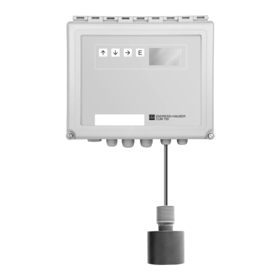
CUM 750 / CUS 70 Instrument description 2.3 Design and functional description The measuring system consists of the following system components: • CUM 750 transmitter • Ultrasonic sensor CUS 70 1 CUM 750 transmitter 2 Operating keys 3 Main switch... -
Page 9: Installation
Installation CUM 750 / CUS 70 Installation 3.1 Dimensions 3.1.1 CUM 750 Transmitter 3.1.2 CUS 70 Sensor Fixing bracket Self-priming cleaning pump (optional) Sensor Endress+Hauser... -
Page 10: Instrument Arrangement
CUM 750 / CUS 70 Installation 3.2 Instrument arrangement Transmitter fixed to scraper bridge Sensor Primary clarifier Transmitter fixed to scraper bridge Sensor Thickener Endress+Hauser... -
Page 11: Instrument Mounting
Installation CUM 750 / CUS 70 3.3 Instrument mounting Weather protection 1. Before you mount the measuring cover (accessories) system, examine the process environment and the physical Meas. transmitter characteristics of the basin: • Basin depth • Approximate location of... -
Page 12: Electrical Connection
CUM 750 / CUS 70 Electrical connection Electrical connection 4.1 Connection terminal blocks a Processor board b Power supply board c TX/RX board d Fine-wire fuse F1A e Pump 1 connection Mains connection g Main switch h LCD contrast setting... -
Page 13: Pin Assignment
Electrical connection CUM 750 / CUS 70 4.2 Pin assignment Endress+Hauser... -
Page 14: Connection Tables
Sensor 4 negative (bl) Note: • The scope of supply for the CUM 750 / CUS 70 measuring system includes 6m of cable. If a cable extension between the transmitter and sensor is required, use a screened cable. • The distance between sensor and transmitter must be no more than 100m. - Page 15 Electrical connection CUM 750 / CUS 70 4.3.3 Connecting the analogue output and serial ports The measuring system is designed for up to four 4-20mA analogue outputs, one per sensor. The connection uses a 14-pin PHOENIX plug-connector, which also contains the pins for the RS 485 and RS 232 serial ports.
- Page 16 CUM 750 / CUS 70 Electrical connection 4.3.4 Switch contacts connection The measuring system is designed to control up to four relays. Connection is by means of two 6-pin PHOENIX plug-in connectors (for two relays). Connecting the X3 terminal block Pin No.
- Page 17 Electrical connection CUM 750 / CUS 70 Connecting Pumps 3 – 4 Pumps 3 and 4 (with Three and Four channel version) are connected using an extra distributor box (optionally available). Connecting X1 terminal block in the distributor box: Pin No. Name...
-
Page 18: Start-Up
CUM 750 / CUS 70 Start-up Start-up Warning! • Before connecting the instrument, make sure the mains voltage rating matches the figure on the nameplate. • A clearly marked mains disconnecting device must be installed in the vicinity of the instrument. -
Page 19: Operation
Operation CUM 750 / CUS 70 Operation 6.1 Key assignment The instrument is operated using the keypad on the front or using a PC connected to the serial interface. In local operating mode, you can move through the menu using the arrow keys '↓ ↓ ↓ ↓ ‘ and '↑ ↑ ↑ ↑ ‘. Select the required option by pressing 'E’. - Page 20 CUM 750 / CUS 70 Operation 6.2.1 DIGITAL display mode In this display mode, you can view the distance between the sensor position and the separation zone (measuring mode = FROM SURFACE) or the distance between basin bottom and the separation zone (measuring mode = FROM BOTTOM) displayed numerically using a selected unit (m, cm, ft, in, yd).
- Page 21 Operation CUM 750 / CUS 70 6.2.2 GRAPHIC display mode This display mode shows the strength of the feedback signal inside the basin. This type of display is useful when the system is installed for the first time to view the material stratification in the basin.
-
Page 22: Menu Structure
CUM 750 / CUS 70 Operation 6.3 Menu structure The menu for setting parameters is split into two levels: ADVANCED OFF and ADVANCED ON. ADVANCED OFF allows access to the parameters required to adapt the system to the application. ADVANCED ON allows access to all parameters. This is only necessary for servicing. The pa- rameters in the ADVANCED ON menu are only accessible by entering a code number. - Page 23 Operation CUM 750 / CUS 70 Menu structure SYSTEM SETUP Measure LEVEL / RANGE Units [m], [cm], [in], [ft], [yd] Recall / Save FACTORY PRESET / USER No. of points MODIFY POINTS Tank config Tank depth [m], [cm], [in], [ft], [yd]...
-
Page 24: System Setup Menu
CUM 750 / CUS 70 Operation 6.5 SYSTEM SETUP menu SYSTEM SETUP Measure LEVEL / RANGE Units [m], [cm , [in], [ft], [yd] Recall / Save FACTORY PRESET / USER No. of points 1 ... 4 Function: The SYSTEM SETUP option allows access to the general basic settings which are valid for all connected sensors and measuring points. -
Page 25: Modify Points Menu
Operation CUM 750 / CUS 70 6.6 MODIFY POINTS menu MODIFY POINTS Tank config Tank depth [m], [cm, [in], [ft], [yd] Zero adjust [m], [cm, [in], [ft], [yd] Dwell time Min. range [m], [cm, [in], [ft], [yd] Max. range [m], [cm, [in], [ft], [yd]... - Page 26 CUM 750 / CUS 70 Operation 6.6.1 TANK CONFIG submenu Enter specific data for the measuring point using the submenu TANK CONFIG. Zero point Scraper Tank depth: Set the tank depth for each sensor position. To obtain the correct display of the sludge level, it is important to enter the exact tank depth.
- Page 27 Operation CUM 750 / CUS 70 6.6.2 ACOUSTICS submenu You can enter the specific data for the ultrasonic signal gain using the ACOUSTICS submenu. Gain start: Set the entire gain for the system by choosing the GAIN START command. From a functional aspect, these parameters are equivalent to a volume control.
- Page 28 CUM 750 / CUS 70 Operation Gain increment: Set the gain increments of the measuring signal between each screen refresh, e.g. Gain 20 + 0.5. Enable the automatic gain "Auto gain" function first. Setting range: 0.5 ... 5.0 steps Clip count: Set the number of pixels which the 75% display height can exceed before the gain is scaled back, e.g.
- Page 29 Operation CUM 750 / CUS 70 Threshold: The THRESHOLD creates the primary condition for the measuring system for tracking the separation zones based on the selected algorithm. The system searches for a point (on the graphic display) where the signal strength has at least a "threshold value percentage" of the strongest signal (100% of the display height).
-
Page 30: Modify Outputs Menu
CUM 750 / CUS 70 Operation 6.6.4 REBOOT TRACK submenu Restart the instrument using this function. The settings entered in the MODIFY POINTS menu are activated. The instrument carries out an initialisation in the same way as on first start-up. - Page 31 Operation CUM 750 / CUS 70 20 mA setpoint: This function allocates a basin depth to the 20mA signal. The function is dependent on the measuring mode set. If you select the "LEVEL" measuring mode, the 20mA setting should lie within the min. and Max.
- Page 32 CUM 750 / CUS 70 Operation Setpoint: Set the switch point of the relay. Setting range: 0 ... 100m Dead band: Set the value at which the relay status should be maintained until the measured variable has changed by the hysteresis value.
-
Page 33: Advanced Menu
Operation CUM 750 / CUS 70 6.8 ADVANCED menu ADVANCED ON / OFF ON / OFF Choose whether all the parameters should be visible or only the basic version parameters which are sufficient for normal operation. Operation: Move through the submenu by pressing the → → → → key, select numeric values by pressing the '↑ ↑ ↑ ↑ ‘ / '↓ ↓ ↓ ↓ ‘ keys (see Chap. -
Page 34: Maintenance
Endress+Hauser service organisation. You can find the address of your nearest E+H sales centre on the rear page of this manual. 7.1 Maintenance plan The CUM 750 / CUS 70 measuring system generally requires little maintenance. However, for trouble- free functionality, you should carry out the following servicing work: Every three months: Clean sensor Remove sediment with spraywater. -
Page 35: Software Update
3. Press and hold down ENTER key. 4. Switch on instrument. 5. Release ENTER key. 6. Enter previous or new parameters. 7.3 Spare parts You can order the following spare parts for the CUM 750 measuring system: • Cleaning pump Order No.: 51503795 •... -
Page 36: Accessories
CUM 750 / CUS 70 Accessories Accessories You can order the following accessories for the CUM 750 / CUS 70 measuring system separately: • Weather protection cover CYY 101 for CUM 750 Stainless steel SS 304 , (h x w x d) 320 x 300 x 270mm Order No.: 50061258... - Page 37 Accessories CUM 750 / CUS 70 • Wall bracket for CUS 70 with 300mm wall clearance Order No.: 51503581 • Railing bracket for CUS 70 with 300mm basin wall clearance Order No.: 51503582 • Railing bracket for CUS 70 with 300mm basin wall clearance, weather protection cover Order No.: 51503583...
-
Page 38: Technical Data
CUM 750 / CUS 70 Technical data Technical data CUM 750 transmitter General data Manufacturer Endress+Hauser Instrument name CUM 750 sludge level transmitter Mechanical design Dimensions (l x w x d) 265 × 227 × 160mm Weight approx. 4kg Measured variable display... - Page 39 Technical data CUM 750 / CUS 70 CUS 70 Sensor Mechanical design Dimensions (l x ∅) 105 x ∅ 63mm Weight Approx. 0.5kg Cable length Max. distance between sensor & transmitter 100m Process connection for immersion tube G1 thread Materials...
- Page 40 Index CUM 750 / CUS 70 10 Appendix 10.1 CUM 750 settings Main menu Submenus Setting range / Default Setting Units setting Measure LEVEL / RANGE LEVEL SYSTEM SETUP Units [m], [cm],[in], [ft],[yd] Recall / Save No. of points 1 ... 4...
- Page 41 Stichwortverzeichnis CUM 750 / CUS 70 Main menu Submenus Setting range / Default Setting Units setting 4 ... 20mA 4mA setpoint 0 ... 100m 0.5m MODIFY OUTPUTS 20mA setpoint 0 ... 100m 3.8m Trim 4mA 0 ... 100 Trim 20mA 0 ...
- Page 42 Index CUM 750 / CUS 70 11 Index 4-20mA..............29 Main menu ............21 Maintenance ............33 Maintenance plan..........33 Materials ............37, 38 Accessories............35 Menu structure ..........21, 22 ACOUSTICS ............26 MODIFY OUTPUTS ..........29 ADVANCED ............32 MODIFY POINTS ..........24 Ambient conditions..........37 Mounting ...............10 Analogue output ............14 Auxiliary energy.............13...
- Page 43 Tel. ++6 75 (3) 25 11 88, Fax (3) 25 95 56 Austria Fax (11) 5 0 31 30 67 Endress+Hauser Ges.m.b.H. Poland Philippines Wien Endress+Hauser Polska Sp. z o.o. Canada Brenton Industries Inc. Tel. ++43 (1) 8 80 56-0, Fax (1) 8 80 56-35 Warszawy Endress+Hauser Ltd. Makati Metro Manila Tel.