
Related Manuals for Endress+Hauser Turbimax CUS50D


Summary of Contents for Endress+Hauser Turbimax CUS50D
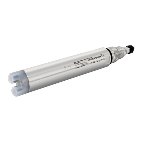
- Page 1 Products Solutions Services BA01846C/07/EN/03.20 71473151 2020-02-10 Operating Instructions Turbimax CUS50D Absorption sensor for turbidity and solids measurements...
-
Page 3: Table Of Contents
Turbimax CUS50D Table of contents Table of contents About this document ... 4 Maintenance ....38 Warnings . -
Page 4: About This Document
About this document Turbimax CUS50D About this document Warnings Structure of information Meaning This symbol alerts you to a dangerous situation. DANGER Failure to avoid the dangerous situation will result in a fatal or serious injury. Causes (/consequences) If necessary, Consequences of non- compliance (if applicable) ‣... -
Page 5: Symbols On The Device
Turbimax CUS50D About this document Symbols on the device Symbol Meaning Reference to device documentation Endress+Hauser... -
Page 6: Basic Safety Instructions
Basic safety instructions Turbimax CUS50D Basic safety instructions Requirements for personnel • Installation, commissioning, operation and maintenance of the measuring system may be carried out only by specially trained technical personnel. • The technical personnel must be authorized by the plant operator to carry out the specified activities. -
Page 7: Product Safety
Turbimax CUS50D Basic safety instructions Ensure that electrical cables and hose connections are undamaged. Do not operate damaged products, and protect them against unintentional operation. Label damaged products as defective. During operation: ‣ If faults cannot be rectified: products must be taken out of service and protected against unintentional operation. -
Page 8: Product Description
Product description Turbimax CUS50D Product description Product design The sensor features a sensor head with 2 path lengths of 5 mm (0.2 in) and 10 mm (0.39 in). A0036825 1 CUS50D sensor head Light sources 10 mm (0.39 in) Light sources 5 mm (0.2 in) - Page 9 Turbimax CUS50D Product description A0036368 2 Versions With clamp With compressed air cleaning 3.1.1 Measuring principle The sensor operates on the principle of light attenuation in accordance with ISO 7027 and meets the requirements of this standard. It is suitable for measurements in the average to high turbidity range and for the measurement of solids content.
-
Page 10: Incoming Acceptance And Product Identification
Incoming acceptance and product identification Turbimax CUS50D Incoming acceptance and product identification Incoming acceptance Verify that the packaging is undamaged. Notify the supplier of any damage to the packaging. Keep the damaged packaging until the issue has been resolved. -
Page 11: Scope Of Delivery
Endress+Hauser Conducta GmbH+Co. KG Dieselstraße 24 D-70839 Gerlingen Scope of delivery The delivery comprises: • 1 Turbimax CUS50D sensor, version as ordered • 1 Operating Instructions BA01846C Certificates and approvals 4.4.1 mark The product meets the requirements of the harmonized European standards. As such, it complies with the legal specifications of the EU directives. -
Page 12: Installation
Installation Turbimax CUS50D Installation Installation conditions 5.1.1 Dimensions NPT3/4" GI“ 36 (1.4) (1.57) A0036366 3 Dimensions. Dimensions: mm (in) Endress+Hauser... - Page 13 Turbimax CUS50D Installation NPT3/4" GI“ 36 (1.4) (1.57) (2.52) A0036582 4 Dimensions with clamp. Dimensions: mm (in) Endress+Hauser...
- Page 14 Installation Turbimax CUS50D 4.7 (0.19) 3.8 (1.5) 61 (2.4) A0036826 5 Dimensions for compressed air cleaning. Dimensions: mm (in) Compressed air cleaning: 2 bar (29 psi) maximum pressure Endress+Hauser...
- Page 15 Turbimax CUS50D Installation 5.1.2 Orientation in pipes Detail A Detail A 90° A0029259 6 Permitted and unacceptable orientations in pipes • The pipeline diameter must be at least 50 mm (2 in). • Install the sensor in places with consistent flow conditions.
-
Page 16: Mounting The Sensor
Mounting the sensor 5.2.1 Measuring system A complete measuring system comprises: • Turbimax CUS50D turbidity sensor • Liquiline CM44x multi-channel transmitter • Direct installation in a pipe connection (Clamp 2" ) or • Assembly: • Flow assembly e.g. Flowfit CUA252 or CUA120 or •... - Page 17 Turbimax CUS50D Installation A0036713 9 Measuring system with CUA252 flow assembly Liquiline CM44x multi-channel transmitter Turbimax CUS50D turbidity sensor CUA252 flow assembly Direction of flow 5.2.2 Mounting options Installing with CUA120 flow assembly The installation angle is 90°. The arrow indicates the flow direction; it runs from the 10 mm (0.39 in) path to the...
- Page 18 Installation Turbimax CUS50D Installing with CUA252, CUA262 or CYA251 flow assembly The installation angle is 90°. The arrow indicates the flow direction; it runs from the 10 mm (0.39 in) path to the 5 mm (0.2 in) path. A0036837 11 Installing with CUA252 flow assembly The installation angle is 90°.
- Page 19 Turbimax CUS50D Installation The installation angle is 90°. The arrow indicates the flow direction; it runs from the 10 mm (0.39 in) path to the 5 mm (0.2 in) path. A0041336 13 Installing with CYA251 flow assembly Installing with CUA451 retractable assembly The installation angle is 90°.
-
Page 20: Mounting The Compressed Air Cleaning
Installation Turbimax CUS50D Installing with Flexdip CYA112 immersion assembly and Flexdip CYH112 holder The installation angle is 0°. The arrow indicates the flow direction; it runs from the 10 mm (0.39 in) path to the 5 mm (0.2 in) path. -
Page 21: Electrical Connection
Turbimax CUS50D Electrical connection Electrical connection WARNING Device is live! Incorrect connection may result in injury or death! ‣ The electrical connection may be performed only by an electrical technician. ‣ The electrical technician must have read and understood these Operating Instructions and must follow the instructions contained therein. - Page 22 Electrical connection Turbimax CUS50D Sensor 1 Sensor Sensor 1 Sensor 2 Sensor A0033092 17 Sensor connection to sensor input (left) or via M12 connector (right) Connecting the cable shield Cable sample (does not necessarily correspond to the original cable supplied) ...
-
Page 23: Ensuring The Degree Of Protection
Turbimax CUS50D Electrical connection Ensuring the degree of protection Only the mechanical and electrical connections which are described in these instructions and which are necessary for the required, designated use, may be carried out on the device delivered. ‣ Exercise care when carrying out the work. -
Page 24: Commissioning
Commissioning Turbimax CUS50D Commissioning Function check Prior to initial commissioning, ensure that: • The sensor is correctly installed • The electrical connection is correct. ‣ Before commissioning, check the chemical compatibility of materials, the temperature range and the pressure range. -
Page 25: Operation
Turbimax CUS50D Operation Operation Adapting the measuring device to the process conditions 8.1.1 Applications The "Absorption" and "Formazine" applications are calibrated at the factory. The absorption factory calibration is used as the basis for precalibrating additional applications and optimizing them for the different media characteristics. - Page 26 Operation Turbimax CUS50D The desired data record is activated by selecting the corresponding application. It can be adapted to that application using the following options: • Calibration (1 to 10 points) • Entering of a factor (multiplication of measured values by a constant factor) •...
- Page 27 Turbimax CUS50D Operation Application Measuring path lengths 5 mm (0.2 in) 10 mm (0.39 in) Automatic Kaolin Sludge Auto sludge Product loss Generally, a longer measuring path (10 mm (0.39 in)) is recommended for measuring lower absorption values and thus for low-viscosity or watery liquids.
- Page 28 Operation Turbimax CUS50D The sensor does not need to be taken out of the medium for calibration; it can be calibrated directly on-site in the application. Before the calibration, ensure that the measuring gap is not fouled with deposit buildup.
- Page 29 Turbimax CUS50D Operation 2-point calibration Measured value deviations are to be compensated for at 2 different points in an application (e.g. the maximum and minimum value of the application). This aims to ensure a maximum level of accuracy between these two extreme values.
- Page 30 Operation Turbimax CUS50D 3-point calibration A0039322 23 Principle of multipoint calibration (3 points) Measured value Target sample value Factory calibration Application calibration Select data record. Set 3 different calibration points in the medium and specify the corresponding set points.
- Page 31 Turbimax CUS50D Operation The specifications comprise the following: • The maximum permitted deviation in temperature measurement • The maximum permitted deviation in measured value as a % • The minimum time frame in which these values must be maintained The calibration resumes as soon as the stability criteria for signal values and temperature have been reached.
- Page 32 Operation Turbimax CUS50D f = 1.1 A0039329 24 Principle of factor calibration Measured value Target sample value Factory calibration Factor calibration Offset With the "Offset" function, the measured values are offset by a constant amount (added or subtracted). Endress+Hauser...
- Page 33 Turbimax CUS50D Operation A0039330 25 Principle of an offset Measured value Target sample value Factory calibration Offset calibration 8.1.3 Cyclic cleaning For cyclic cleaning, compressed air is the most suitable option. The cleaning unit is either supplied or can be retrofitted, and is attached to the sensor head. The following settings are...
- Page 34 Strong Strong filtering, low sensitivity, slow response to changes (25 seconds) Specialist This menu is designed for the Endress+Hauser Service Department. None Air bubble trap In addition to the measured value filter, the sensor also features a filter function to suppress the measured errors caused by air bubbles.
- Page 35 Turbimax CUS50D Operation Preparatory steps for the function check with the calibration kit Clean the sensor and dry it → 38. Fix the sensor in place (e.g. with a laboratory stand). A0036827 Fit the calibration kit (A) in the correction direction on the sensor head (B). The direction is specified on the calibration kit.
- Page 36 Operation Turbimax CUS50D Compare the measured value with the reference value on the calibration kit. The function check is positive if the deviation is within the permitted tolerances (see → 34). Reference tool Solid state reference, CUS50D kit Tolerance ±...
-
Page 37: Diagnostics And Troubleshooting
Turbimax CUS50D Diagnostics and troubleshooting Diagnostics and troubleshooting General troubleshooting When troubleshooting, the entire measuring point must be taken into account: • Transmitter • Electrical connections and cables • Assembly • Sensor The possible causes of error in the following table relate primarily to the sensor. -
Page 38: Maintenance
Maintenance Turbimax CUS50D Maintenance CAUTION Acid or medium Risk of injury, damage to clothing and the system! ‣ Switch off the cleaning unit before removing the sensor from the medium. ‣ Wear protective goggles and safety gloves. ‣ Clean away splashes on clothes and other objects. -
Page 39: Repair
The product must be returned if repairs or a factory calibration are required, or if the wrong product was ordered or delivered. As an ISO-certified company and also due to legal regulations, Endress+Hauser is obliged to follow certain procedures when handling any returned products that have been in contact with medium. -
Page 40: Accessories
Accessories Turbimax CUS50D Accessories The following are the most important accessories available at the time this documentation was issued. ‣ For accessories not listed here, please contact your Service or Sales Center. 12.1 Assemblies FlowFit CUA120 • Flange adapter for mounting turbidity sensors •... -
Page 41: Holder
Turbimax CUS50D Accessories 12.2 Holder Flexdip CYH112 • Modular holder system for sensors and assemblies in open basins, channels and tanks • For Flexdip CYA112 water and wastewater assemblies • Can be affixed anywhere: on the ground, on the coping stone, on the wall or directly onto railings. -
Page 42: Compressed Air Cleaning
Accessories Turbimax CUS50D 60 ... 64 (2.36 ... 2.52) (1.42) A0030819 27 Pipe connection with weld-in adapter. Dimensions: mm (in) 12.4 Compressed air cleaning Compressed air cleaning for CUS50D • Connection: 6 mm (0.24 in) • Pressure: 1.5 to 2 bar (21.8 to 29 psi) •... -
Page 43: Technical Data
Turbimax CUS50D Technical data Technical data 13.1 Input 13.1.1 Measured variables • Turbidity • Absorption • Solids content • Product loss • Temperature 13.1.2 Measuring range Application Specified operating range Maximum operating range Absorption factory calibration 0.000 to 5.000 AU or 0.000 to 10.000 OD... -
Page 44: Environment
Technical data Turbimax CUS50D Sludge/auto 10 % of the measured value or 5 % of the upper range value (the greater value applies in each sludge case); applies to sensors that are calibrated for the observed measuring range Product loss Not specified;... -
Page 45: Process
Turbimax CUS50D Technical data 13.3.3 Degree of protection IP 68 (1.8 m (5.91 ft) water column over 20 days, 1 mol/l KCl) 13.4 Process 13.4.1 Process temperature range –20 to 85 °C (–4 to 185 °F) 13.4.2 Process pressure range 0 to 5 bar (0 to 73 psi) absolute 13.4.3... -
Page 46: Index
Index Turbimax CUS50D Index 0 … 9 Multipoint calibration ....27 1-point calibration ....28 2-point calibration . - Page 48 *71473151* 71473151 www.addresses.endress.com...