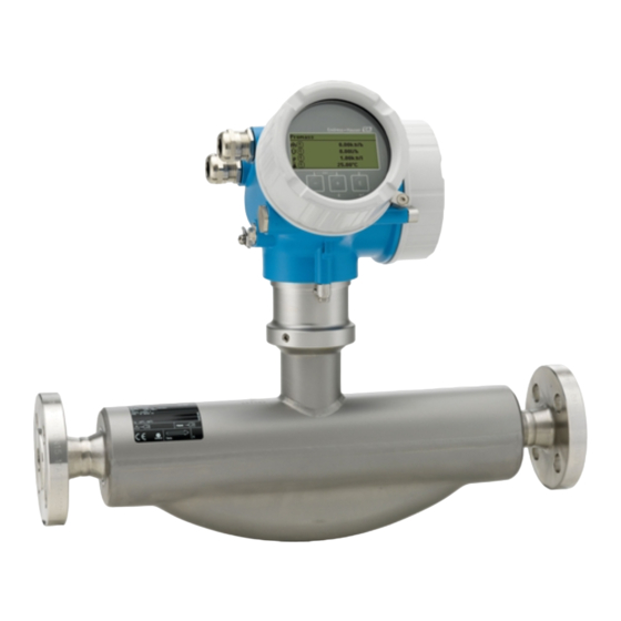
Endress+Hauser Proline Promass E 200 Brief Operating Instructions
Coriolis flowmeter
Hide thumbs
Also See for Proline Promass E 200:
- Operating instructions manual (246 pages) ,
- Technical information (68 pages) ,
- Operating instructions manual (164 pages)
Table of Contents
Advertisement
Quick Links
KA00050D/06/EN/16.14
71241802
Products
Brief Operating Instructions
Proline Promass E 200
Coriolis flowmeter
These Instructions are Brief Operating Instructions; they are
not a substitute for the Operating Instructions pertaining to
the device.
Detailed information about the device can be found in the
Operating Instructions and the other documentation:
• On the CD-ROM supplied (is not included in the delivery for
all device versions).
• Available for all device versions via:
– Internet:
www.endress.com/deviceviewer
– Smart phone/tablet: Endress+Hauser Operations App
Description of the procedure (→ 10)
Solutions
Services
Advertisement
Table of Contents

Related Manuals for Endress+Hauser Proline Promass E 200


Summary of Contents for Endress+Hauser Proline Promass E 200
- Page 1 Operating Instructions and the other documentation: • On the CD-ROM supplied (is not included in the delivery for all device versions). • Available for all device versions via: – Internet: www.endress.com/deviceviewer – Smart phone/tablet: Endress+Hauser Operations App Description of the procedure (→ 10)
-
Page 2: Table Of Contents
Table of contents Proline Promass E 200 Table of contents Document information ............3 Symbols used . -
Page 3: Document Information
Proline Promass E 200 Document information Document information Symbols used 1.1.1 Safety symbols Symbol Meaning DANGER! DANGER This symbol alerts you to a dangerous situation. Failure to avoid this situation will result in serious or fatal injury. A0011189-EN WARNING! WARNING This symbol alerts you to a dangerous situation. - Page 4 Document information Proline Promass E 200 1.1.3 Tool symbols Symbol Meaning Flat blade screwdriver A0011220 Allen key A0011221 Open-ended wrench A0011222 1.1.4 Symbols for certain types of information Symbol Meaning Allowed Indicates procedures, processes or actions that are allowed. A0011182 Preferred Indicates procedures, processes or actions that are preferred.
-
Page 5: Basic Safety Instructions
Proline Promass E 200 Basic safety instructions 1.1.5 Symbols in graphics Symbol Meaning 1, 2, 3,... Item numbers Series of steps … A, B, C, ... Views A-A, B-B, C-C, ... Sections Flow direction A0013441 Hazardous area Indicates a hazardous area. -
Page 6: Workplace Safety
Verification for borderline cases: ‣ For special fluids and fluids for cleaning, Endress+Hauser is glad to provide assistance in verifying the corrosion resistance of fluid-wetted materials, but does not accept any warranty or liability as minute changes in the temperature, concentration or level of contamination in the process can alter the corrosion resistance properties. -
Page 7: Operational Safety
It meets general safety standards and legal requirements. It also complies with the EC directives listed in the device-specific EC Declaration of Conformity. Endress+Hauser confirms this by affixing the CE mark to the device. IT security We only provide a warranty if the device is installed and used as described in the Operating Instructions. -
Page 8: Product Description
Product description Proline Promass E 200 Product description Product design A0014056 1 Important components of a measuring device Electronics compartment cover Display module Main electronics module Cable glands Transmitter housing (incl. HistoROM) I/O electronics module Terminals (spring loaded terminals, pluggable) -
Page 9: Incoming Acceptance And Product Identification
A0013697 • If one of the conditions is not satisfied, contact your Endress+Hauser Sales Center. • Depending on the device version, the CD-ROM might not be part of the delivery! In such cases, the technical documentation is available via the Internet or via the Endress +Hauser Operations App, see the "Device documentation"... -
Page 10: Product Identification
• Enter serial numbers from nameplates in W@M Device Viewer (www.endress.com/deviceviewer): All information about the measuring device is displayed. • Enter the serial number from the nameplates into the Endress+Hauser Operations App or scan the 2-D matrix code (QR code) on the nameplate with the Endress+Hauser Operations App: all the information for the measuring device is displayed. -
Page 11: Storage And Transport
Enter the serial number (Ser. no.) of the device: see nameplate (→ 2, 10). All the associated documentation is displayed. Endress+Hauser Operations App The Endress+Hauser Operations App is available both for android smart phones (Google Play store) and for iPhones and iPads (App Store). Via the serial number: Launch the Endress+Hauser Operations App. -
Page 12: Transporting The Product
Storage and transport Proline Promass E 200 Transporting the product WARNING Center of gravity of the measuring device is higher than the suspension points of the webbing slings. Risk of injury if the measuring device slips. ‣ Secure the measuring device from rotating or slipping. - Page 13 Proline Promass E 200 Storage and transport A0015605 Endress+Hauser...
-
Page 14: Installation
Installation Proline Promass E 200 Installation Installation conditions No special measures such as supports are necessary. External forces are absorbed by the construction of the device. 6.1.1 Mounting position Mounting location A0015595 Installation in down pipes However, the following installation suggestion allows for installation in an open vertical pipeline. - Page 15 Proline Promass E 200 Installation A0015596 3 Installation in a down pipe (e.g. for batching applications) Supply tank Sensor Orifice plate, pipe restriction Valve Batching tank Ø orifice plate, pipe restriction [mm] [in] [mm] [in] ³⁄₈ 0.24 ½ 0.40 0.55...
- Page 16 Installation Proline Promass E 200 Orientation The direction of the arrow on the sensor nameplate helps you to install the sensor according to the flow direction. Orientation Recommendation Vertical orientation A0015591 Horizontal orientation, transmitter head up Exception: A0015589 Horizontal orientation, transmitter...
- Page 17 Proline Promass E 200 Installation Inlet and outlet runs No special precautions need to be taken for fittings which create turbulence, such as valves, elbows or T-pieces, as long as no cavitation occurs (→ 17). A0015597 A0015598 For the dimensions and installation lengths of the device, see the "Technical Information"...
- Page 18 Installation Proline Promass E 200 NOTICE Electronics overheating on account of thermal insulation! ‣ Observe maximum permitted insulation height of the transmitter neck so that the transmitter head is completely free. mm (in) A0016749 Heating NOTICE Electronics can overheat due to elevated ambient temperature! ‣...
-
Page 19: Mounting The Measuring Device
Proline Promass E 200 Installation RUPTURE DISK A0007823 4 Rupture disk label ‣ After the rupture disk is actuated, do not operate the measuring device any more. For detailed information about using a rupture disk, refer to the Operating Instructions... - Page 20 Installation Proline Promass E 200 6.2.3 Mounting the measuring device WARNING Danger due to improper process sealing! ‣ Ensure that the inside diameters of the gaskets are greater than or equal to that of the process connections and piping. ‣...
-
Page 21: Post-Installation Check
Proline Promass E 200 Installation 6.2.5 Turning the display module 3 mm A0013905 Post-installation check Is the device undamaged (visual inspection)? Does the measuring device conform to the measuring point specifications? For example: • Process temperature • Process pressure (refer to the chapter on "Material load curves" of the "Technical Information"... -
Page 22: Electrical Connection
Electrical connection Proline Promass E 200 Electrical connection The measuring device does not have an internal circuit breaker. For this reason, assign the measuring device a switch or power-circuit breaker so that the power supply line can be easily disconnected from the mains. - Page 23 Proline Promass E 200 Electrical connection Cable diameter • Cable glands supplied: M20 × 1.5 with cable 6 to 12 mm (0.24 to 0.47 in) • Plug-in spring terminals for device version without integrated overvoltage protection: wire cross-sections 0.5 to 2.5 mm (20 to 14 AWG) •...
- Page 24 Electrical connection Proline Promass E 200 7.1.3 Terminal assignment Transmitter Connection versions A0013570 A0018161 Maximum number of terminals, without integrated overvoltage Maximum number of terminals, with integrated protection overvoltage protection Output 1 (passive): supply voltage and signal transmission Output 2 (passive): supply voltage and signal transmission Ground terminal for cable shield Order code for "Output"...
- Page 25 Proline Promass E 200 Electrical connection 7.1.5 Shielding and grounding Optimum electromagnetic compatibility (EMC) of the fieldbus system can only be guaranteed if the system components and, in particular, the lines are shielded and the shield forms as complete a cover as possible. A shield coverage of 90% is ideal.
- Page 26 Electrical connection Proline Promass E 200 A0019004 Controller (e.g. PLC) Segment coupler PROFIBUS DP/PA Cable shield T-box Measuring device Local grounding Bus terminator Potential matching line NOTICE In systems without potential equalization, the multiple grounding of the cable shield causes mains frequency equalizing currents! Damage to the bus cable shield.
- Page 27 Proline Promass E 200 Electrical connection An external power supply is required for each output. The following supply voltage values apply for PROFIBUS PA and the pulse/frequency/switch output: Minimum terminal Maximum terminal Order code for "Output" voltage voltage 1) 2)
-
Page 28: Connecting The Measuring Device
Electrical connection Proline Promass E 200 R [ ] U [V] A0013563 Operating range 1.1 For order code for "Output", option A "4-20 mA HART"/option B "4-20 mA HART, pulse/frequency/ switch output" with Ex i and option C "4-20 mA HART, 4-20 mA"... - Page 29 Proline Promass E 200 Electrical connection Connection via terminals 3 mm 20 mm 10 (0.4) mm (in) A0013836 ‣ Connect the cable in accordance with the terminal assignment . For HART communication: When connecting the cable shielding to the ground terminal, observe the grounding concept of the facility.
-
Page 30: Hardware Settings
Electrical connection Proline Promass E 200 Hardware settings 7.3.1 Setting the device address PROFIBUS PA The address must always be configured for a PROFIBUS DP/PA device. The valid address range is between 1 and 126. In a PROFIBUS DP/PA network, each address can only be assigned once. -
Page 31: Ensuring The Degree Of Protection
Proline Promass E 200 Electrical connection 2 + 8 = 10 A0015902 6 Example of hardware addressing; switch 8 is set to the "OFF" position; switches 1 to 7 define the address. Software addressing Set switch 8 to "ON". -
Page 32: Post-Connection Check
Electrical connection Proline Promass E 200 A0013960 Insert dummy plugs into unused cable entries. Post-connection check Are cables or the device undamaged (visual inspection)? Do the cables comply with the requirements (→ 22)? Do the cables have adequate strain relief? ... -
Page 33: Operation Options
Proline Promass E 200 Operation options Operation options Structure and function of the operating menu 8.1.1 Structure of the operating menu Operating menu for operators and maintenances Language Operation Setup Diagnostics Operating menu for experts Expert A0014058-EN 8 Schematic structure of the operating menu 8.1.2... -
Page 34: Access To The Operating Menu Via The Local Display
Operation options Proline Promass E 200 Access to the operating menu via the local display X X X X X X 19.184 mA 12.5 X X X X X X Language à 20.50 English Deutsch Español Français User ABC_ DEFG... - Page 35 Proline Promass E 200 Operation options 8.2.1 Operational display Status area Status signals A0013956 A0013959 A0013958 A0013957 Failure Function check Out of specification Maintenance required Diagnostic behavior Locking Communication A0013961 A0013962 A0013965 A0013963 Alarm Warning Device locked Remote operation enabled...
- Page 36 Operation options Proline Promass E 200 8.2.2 Navigation view Status area The following appears in the status area of the navigation view in the top right corner: • Of the submenu – The direct access code for the parameter you are navigating to (e.g. 0022-1) –...
- Page 37 Proline Promass E 200 Operation options Correction symbols under A0013990 A0013991 A0013989 A0013988 Clears all entered characters. Moves the input position Moves the input position Deletes one character one position to the left. one position to the right. immediately to the left of the input position.
- Page 38 Operation options Proline Promass E 200 Meaning Escape key combination (press keys simultaneously) In a menu, submenu • Pressing the key briefly: – Exits the current menu level and takes you to the next higher level. – If help text is open, closes the help text of the parameter.
- Page 39 Proline Promass E 200 Operation options 8.2.6 User roles and related access authorization The two user roles "Operator" and "Maintenance" have different write access to the parameters if the customer defines a user-specific access code. This protects the device configuration via the local display from unauthorized access (→...
-
Page 40: Access To The Operating Menu Via The Operating Tool
Operation options Proline Promass E 200 Switching on the keypad lock ‣ The device is in the measured value display. Press the + + keys simultaneously. The message Keylock on appears on the display: The keypad lock is switched on. - Page 41 Proline Promass E 200 Operation options 8.3.1 Via HART protocol A0013764 9 Options for remote operation via HART protocol Control system (e.g. PLC) Transmitter power supply unit, e.g. RN221N (with communication resistor) Connection for Commubox FXA195 and Field Communicator 475 Field Communicator 475 Computer with operating tool (e.g.
-
Page 42: System Integration
Proline Promass E 200 8.3.2 Via service interface (CDI) A0014019 Service interface (CDI = Endress+Hauser Common Data Interface) of the measuring device Commubox FXA291 Computer with "FieldCare" operating tool with COM DTM "CDI Communication FXA291" System integration For information on system integration, see the Operating Instructions for the device (→... -
Page 43: Switching On The Measuring Device
Proline Promass E 200 Commissioning 10.2 Switching on the measuring device After a successful function check, switch on the measuring device. After a successful startup, the local display switches automatically from the startup display to the operational display. If nothing appears on the local display or a diagnostic message is displayed, refer to the device' s operating instructions which can be found on the CD-ROM supplied with the device. -
Page 44: Defining The Tag Name
Commissioning Proline Promass E 200 Wizard Meaning Select medium Defining the medium Current output 1 Configuring output 1 Current output 2 Configuring output 2 Pulse/frequency/switch output Configuring the selected output type Display Configuring the measured value display Output conditioning Defining the output conditioning... - Page 45 Proline Promass E 200 Commissioning Defining the access code via local display Navigate to the Enter access code parameter. Define a max. 4-digit numeric code as an access code. Enter the access code again to confirm the code. The -symbol appears in front of all write-protected parameters.
-
Page 46: Diagnostic Information
Diagnostic information Proline Promass E 200 XXXXXXXXXXXXX 3 mm A0013768 Loosen the securing clamp. Unscrew the electronics compartment cover. Pull out the display module with a gentle rotational movement. To make it easier to access the lock switch, attach the display module to the edge of the electronics compartment. - Page 47 Proline Promass E 200 Diagnostic information X X X X X X X X X X X X X X 20.50 S801 Supply voltage Menu Diagnostic list Diagnostics 1 S801 Supply voltage Diagnostics 2 Diagnostics 3 Supply voltage (ID:203) S801 0d00h02m25s...
- Page 48 www.addresses.endress.com...