
Related Manuals for Endress+Hauser Proline Prosonic Flow E 100 HART


Summary of Contents for Endress+Hauser Proline Prosonic Flow E 100 HART
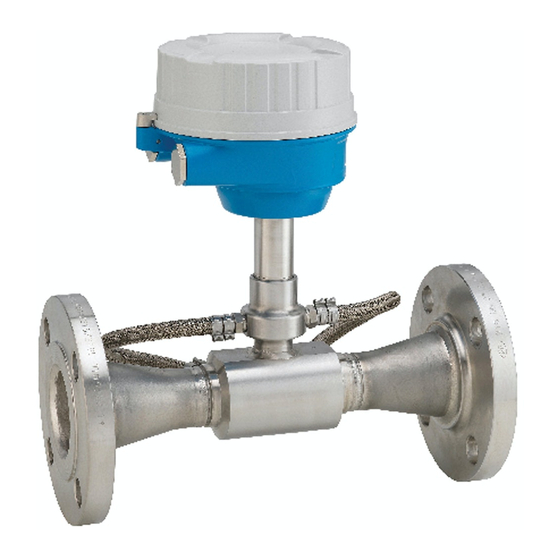
- Page 1 Products Solutions Services BA01769D/06/EN/02.19 71455467 2019-11-01 Valid as of version 01.00.zz (Device firmware) Operating Instructions Proline Prosonic Flow E 100 HART Ultrasonic time-of-flight flowmeter...
- Page 2 • The manufacturer reserves the right to modify technical data without prior notice. Your Endress+Hauser Sales Center will supply you with current information and updates to these instructions. Endress+Hauser...
-
Page 3: Table Of Contents
Proline Prosonic Flow E 100 HART Table of contents Table of contents 6.2.2 Preparing the measuring device ..19 About this document ....5 6.2.3... - Page 4 ....60 13.3 Endress+Hauser services ....86 10.5.6 Using parameters for device...
-
Page 5: About This Document
Proline Prosonic Flow E 100 HART About this document About this document Document function These Operating Instructions contain all the information that is required in various phases of the life cycle of the device: from product identification, incoming acceptance and storage, to mounting, connection, operation and commissioning through to troubleshooting, maintenance and disposal. -
Page 6: Symbols For
• The W@M Device Viewer : Enter the serial number from the nameplate (www.endress.com/deviceviewer) • The Endress+Hauser Operations App: Enter the serial number from the nameplate or scan the 2-D matrix code (QR code) on the nameplate. For a detailed list of the individual documents along with the documentation code →... -
Page 7: Standard Documentation
Proline Prosonic Flow E 100 HART About this document 1.3.1 Standard documentation Document type Purpose and content of the document Technical Information Planning aid for your device The document contains all the technical data on the device and provides an overview of the accessories and other products that can be ordered for the device. -
Page 8: Basic Safety Instructions
Basic safety instructions Proline Prosonic Flow E 100 HART Basic safety instructions Requirements for the personnel The personnel for installation, commissioning, diagnostics and maintenance must fulfill the following requirements: ‣ Trained, qualified specialists must have a relevant qualification for this specific function and task. -
Page 9: Workplace Safety
Verification for borderline cases: ‣ For special fluids and fluids for cleaning, Endress+Hauser is glad to provide assistance in verifying the corrosion resistance of fluid-wetted materials, but does not accept any warranty or liability as minute changes in the temperature, concentration or level of contamination in the process can alter the corrosion resistance properties. -
Page 10: Security
Basic safety instructions Proline Prosonic Flow E 100 HART IT security We only provide a warranty if the device is installed and used as described in the Operating Instructions. The device is equipped with security mechanisms to protect it against any inadvertent changes to the device settings. -
Page 11: Product Description
Proline Prosonic Flow E 100 HART Product description Product description The device consists of a transmitter and a sensor. The device is available as a compact version: The transmitter and sensor form a mechanical unit. Product design 3.1.1 Device version with HART communication type A0023153 ... -
Page 12: Incoming Acceptance And Product
A0028673 and documents present? • If one of the conditions is not satisfied, contact your Endress+Hauser Sales Center. • Depending on the device version, the CD-ROM might not be part of the delivery! The Technical Documentation is available via the Internet or via the Endress+Hauser Operations App, see the "Product identification"... -
Page 13: Transmitter Nameplate
"Supplementary device-dependent documentation" → 7 • The W@M Device Viewer: Enter the serial number from the nameplate (www.endress.com/deviceviewer) • The Endress+Hauser Operations App: Enter the serial number from the nameplate or scan the 2-D matrix code (QR code) on the nameplate. 4.2.1... -
Page 14: Sensor Nameplate
Incoming acceptance and product identification Proline Prosonic Flow E 100 HART 4.2.2 Sensor nameplate 3 4 5 6 Order code: Ser. no.: Ext. ord. cd.: Size: Ptest = Material: 0044 Patents Date: 322541-0000 13 14 A0013907 3 Example of a sensor nameplate... -
Page 15: Storage And Transport
Proline Prosonic Flow E 100 HART Storage and transport Storage and transport Storage conditions Observe the following notes for storage: ‣ Store in the original packaging to ensure protection from shock. ‣ Do not remove protective covers or protective caps installed on process connections. -
Page 16: Measuring Devices With Lifting Lugs
Installation Proline Prosonic Flow E 100 HART 5.2.2 Measuring devices with lifting lugs CAUTION Special transportation instructions for devices with lifting lugs ‣ Only use the lifting lugs fitted on the device or flanges to transport the device. ‣ The device must always be secured at two lifting lugs at least. - Page 17 Proline Prosonic Flow E 100 HART Installation Orientation The direction of the arrow on the nameplate helps you to install the sensor according to the flow direction (direction of medium flow through the piping). • Install the measuring device in a parallel plane free of external mechanical stress.
-
Page 18: Requirements From Environment And Process
Installation Proline Prosonic Flow E 100 HART Outlet runs when installing external devices If installing an external device, observe the specified distance. 3…5 × DN A0015901 Pressure Installation dimensions For the dimensions and installation lengths of the device, see the "Technical Information"... -
Page 19: Mounting The Measuring Device
Proline Prosonic Flow E 100 HART Installation NOTICE Electronics overheating on account of thermal insulation! ‣ Observe maximum permitted insulation height of the transmitter neck so that the transmitter head is completely free. A0034104 Maximum insulation thickness 2 cm (0.79 in) -
Page 20: Turning The Display Module
Installation Proline Prosonic Flow E 100 HART 6.2.4 Turning the display module The local display is only available with the following device version: Order code for "Display; Operation", option B: 4-line; lit, via communication The display module can be turned to optimize display readability. -
Page 21: Electrical Connection
Proline Prosonic Flow E 100 HART Electrical connection Electrical connection NOTICE The measuring device does not have an internal circuit breaker. ‣ For this reason, assign the measuring device a switch or power-circuit breaker so that the power supply line can be easily disconnected from the mains. -
Page 22: Terminal Assignment
Electrical connection Proline Prosonic Flow E 100 HART 7.1.3 Terminal assignment Transmitter Connection version 4-20 mA HART with pulse/frequency/switch output Order code for "Output", option B Connection methods available Order code Possible options for order code Power "Housing" "Electrical connection"... -
Page 23: Connecting The Measuring Device
Proline Prosonic Flow E 100 HART Electrical connection Connecting the measuring device NOTICE Limitation of electrical safety due to incorrect connection! ‣ Have electrical connection work carried out by appropriately trained specialists only. ‣ Observe applicable federal/national installation codes and regulations. -
Page 24: Ensuring Potential Equalization
Electrical connection Proline Prosonic Flow E 100 HART 3 mm 10 (0.4) A0033696 6 Device version with connection example Cable Disconnect the local display from the main electronics module: Operating Instructions for the device . ‣ Connect the cable in accordance with the terminal assignment . -
Page 25: Special Connection Instructions
Proline Prosonic Flow E 100 HART Electrical connection Special connection instructions 7.3.1 Connection examples Current output 4 to 20 mA HART 4...20 mA A0029055 7 Connection example for 4 to 20 mA HART current output (active) Automation system with current input (e.g. PLC) Cable shield: the cable shield must be grounded at both ends to comply with EMC requirements;... -
Page 26: Ensuring The Degree Of Protection
Electrical connection Proline Prosonic Flow E 100 HART Switch output A0028760 9 Connection example for switch output (passive) Automation system with switch input (e.g. PLC) Power supply Transmitter: Observe input values Ensuring the degree of protection The measuring device fulfills all the requirements for the IP66/67 degree of protection, Type 4X enclosure. -
Page 27: Operation Options
Proline Prosonic Flow E 100 HART Operation options Operation options Overview of operating options A0019598 Computer with Web browser (e.g. Internet Explorer) or with operating tool (e.g. FieldCare, AMS Device Manager, SIMATIC PDM) Field Xpert SFX350 or SFX370 Field Communicator 475 Control system (e.g. -
Page 28: Structure And Function Of The Operating Menu
Operation options Proline Prosonic Flow E 100 HART Structure and function of the operating menu 8.2.1 Structure of the operating menu For an overview of the operating menu for experts: "Description of Device Parameters" document supplied with the device Operating menu for operators and maintenances... -
Page 29: Operating Philosophy
Proline Prosonic Flow E 100 HART Operation options 8.2.2 Operating philosophy The individual parts of the operating menu are assigned to certain user roles (operator, maintenance etc.). Each user role contains typical tasks within the device lifecycle. Menu/parameter User role and tasks... -
Page 30: Access To The Operating Menu Via The Web Browser
Operation options Proline Prosonic Flow E 100 HART Access to the operating menu via the web browser 8.3.1 Function range Thanks to the integrated Web server, the device can be operated and configured via a Web browser and via a service interface (CDI-RJ45) . In addition to the measured values, status information on the device is also displayed and allows the user to monitor the status of the device. -
Page 31: Establishing A Connection
Proline Prosonic Flow E 100 HART Operation options Measuring device: Via CDI-RJ45 service interface Device CDI-RJ45 service interface Measuring device The measuring device has an RJ45 interface. Web server Web server must be enabled; factory setting: ON For information on enabling the Web server → 34... -
Page 32: Logging On
Operation options Proline Prosonic Flow E 100 HART 2. Enter the IP address of the Web server in the address line of the Web browser: 192.168.1.212 The login page appears. 2 3 4 A0029417 Picture of device Device name Device tag (→... -
Page 33: User Interface
Proline Prosonic Flow E 100 HART Operation options 8.3.5 User interface A0032879 Picture of device Device name Device tag Status signal Current measured values Navigation area Local display language Header The following information appears in the header: • Device name •... -
Page 34: Disabling The Web Server
Operation options Proline Prosonic Flow E 100 HART Navigation area If a function is selected in the function bar, the submenus of the function open in the navigation area. The user can now navigate through the menu structure. Working area... -
Page 35: Access To The Operating Menu Via The Operating Tool
VIATOR Bluetooth modem with connecting cable Transmitter Via service interface (CDI) A0014019 Service interface (CDI = Endress+Hauser Common Data Interface) of the measuring device Commubox FXA291 Computer with FieldCare operating tool with COM DTM CDI Communication FXA291 Via service interface (CDI-RJ45) -
Page 36: Field Xpert Sfx350, Sfx370
FieldCare Function scope FDT-based plant asset management tool from Endress+Hauser. It can configure all smart field devices in a system and helps you manage them. By using the status information, it is also a simple but effective way of checking their status and condition. - Page 37 Proline Prosonic Flow E 100 HART Operation options Establishing a connection 1. Start FieldCare and launch the project. 2. In the network: Add a device. The Add device window opens. 3. Select the CDI Communication TCP/IP option from the list and press OK to confirm.
-
Page 38: Devicecare
DeviceCare Function scope Tool to connect and configure Endress+Hauser field devices. The fastest way to configure Endress+Hauser field devices is with the dedicated "DeviceCare" tool. Together with the device type managers (DTMs) it presents a convenient, comprehensive solution. For details, see Innovation Brochure IN01047S Source for device description files See information →... -
Page 39: System Integration
Proline Prosonic Flow E 100 HART System integration System integration Overview of device description files 9.1.1 Current version data for the device Firmware version 01.00.zz • On the title page of the Operating Instructions • On the transmitter nameplate → 12 •... -
Page 40: Other Settings
System integration Proline Prosonic Flow E 100 HART Dynamic variables Measured variables (HART device variables) Primary dynamic variable (PV) Volume flow Secondary dynamic variable (SV) Totalizer 1 Tertiary dynamic variable (TV) Totalizer 2 Quaternary dynamic variable (QV) Totalizer 3 The assignment of the measured variables to the dynamic variables can be modified and assigned as desired via the operating tool using the following parameters: •... - Page 41 Proline Prosonic Flow E 100 HART System integration Navigation "Expert" menu → Communication → HART output → Burst configuration → Burst configuration 1 to n ‣ Burst configuration ‣ Burst configuration 1 to n Burst mode 1 to n → 41 Burst command 1 to n →...
- Page 42 System integration Proline Prosonic Flow E 100 HART Parameter Description Selection / User entry Factory setting Burst variable 0 For HART command 9 and 33: select the • Volume flow Volume flow HART device variable or the process variable. • Mass flow •...
-
Page 43: Commissioning
Proline Prosonic Flow E 100 HART Commissioning Commissioning 10.1 Function check Before commissioning the measuring device: ‣ Make sure that the post-installation and post-connection checks have been performed. • "Post-installation check" checklist→ 20 • "Post-connection check" checklist → 26 10.2... -
Page 44: Setting The System Units
Commissioning Proline Prosonic Flow E 100 HART Navigation "Setup" menu → Device tag Parameter overview with brief description Parameter Description User entry Factory setting Device tag Enter the name for the measuring point. Max. 32 characters, such as Prosonic Flow E 100 letters, numbers or special characters (e.g. - Page 45 Proline Prosonic Flow E 100 HART Commissioning Parameter Description Selection Factory setting Mass unit Select mass unit. Unit choose list Country-specific: • kg • lb Temperature unit Select temperature unit. Unit choose list Country-specific: • °C Result • °F The selected unit applies for: •...
-
Page 46: Configuring The Current Output
Commissioning Proline Prosonic Flow E 100 HART 10.4.3 Configuring the current output The Current output submenu guides you systematically through all the parameters that have to be set for configuring the current output. Navigation "Setup" menu → Current output 1 Structure of the submenu ‣... -
Page 47: Configuring The Pulse/Frequency
Proline Prosonic Flow E 100 HART Commissioning Parameter Prerequisite Description Selection / User Factory setting entry 20 mA value One of the following options is Enter 20 mA value. Signed floating-point Depends on country selected in the Current span number and nominal parameter (→... - Page 48 Commissioning Proline Prosonic Flow E 100 HART Navigation "Setup" menu → Pulse/frequency/switch output 1 Structure of the"Pulse/frequency/switch output 1" submenu ‣ Pulse/frequency/switch output 1 Operating mode → 49 Assign pulse output 1 → 49 Assign frequency output → 50 Switch output function →...
-
Page 49: Configuring The Output
Proline Prosonic Flow E 100 HART Commissioning Switch-off delay → 53 Failure mode → 54 Invert output signal → 49 Configuring the pulse output Navigation "Setup" menu → Pulse/frequency/switch output 1 Parameter overview with brief description Parameter... - Page 50 Commissioning Proline Prosonic Flow E 100 HART Parameter overview with brief description Parameter Prerequisite Description Selection / User Factory setting entry Operating mode – Define the output as a pulse, • Pulse Pulse frequency or switch output. • Frequency • Switch Assign frequency output...
- Page 51 Proline Prosonic Flow E 100 HART Commissioning Parameter Prerequisite Description Selection / User Factory setting entry Measuring value at minimum In the Operating mode Enter measured value for Signed floating-point Depends on country frequency parameter, the Frequency minmum frequency. number and nominal...
- Page 52 Commissioning Proline Prosonic Flow E 100 HART Parameter Prerequisite Description Selection / User Factory setting entry Failure mode In the Operating mode Define output behavior in • Actual value 0 Hz parameter, the Frequency alarm condition. • Defined value option is selected, and one of •...
- Page 53 Proline Prosonic Flow E 100 HART Commissioning Parameter Prerequisite Description Selection / User Factory setting entry Assign diagnostic behavior • In the Operating mode Select diagnostic behavior for • Alarm Alarm parameter, the Switch switch output. • Alarm or warning option is selected.
-
Page 54: Conditioning
Commissioning Proline Prosonic Flow E 100 HART Parameter Prerequisite Description Selection / User Factory setting entry Failure mode – Define output behavior in • Actual status Open alarm condition. • Open • Closed Invert output signal – Invert the output signal. • No •... - Page 55 Proline Prosonic Flow E 100 HART Commissioning Parameter overview with brief description Parameter Prerequisite Description Selection / User Factory setting entry Assign current output – Select process variable for • Off Volume flow current output. • Volume flow • Mass flow • Sound velocity •...
-
Page 56: Configuring The Low Flow Cut Off
Commissioning Proline Prosonic Flow E 100 HART 10.4.6 Configuring the low flow cut off The Low flow cut off submenu contains the parameters that must be set in order to configure the low flow cut off. Structure of the wizard... -
Page 57: Advanced Settings
Proline Prosonic Flow E 100 HART Commissioning 10.5 Advanced settings The Advanced setup submenu together with its submenus contains parameters for specific settings. The number of submenus can vary depending on the device version. Some submenus are not dealt with in the Operating Instructions. These submenus and the parameters they contain are explained in the Special Documentation for the device. -
Page 58: Configuring The Totalizer
Commissioning Proline Prosonic Flow E 100 HART Parameter overview with brief description Parameter Description Selection Factory setting Installation direction Set sign of flow direction to match the • Flow in arrow direction Flow in arrow direction direction of the arrow on the sensor. - Page 59 Proline Prosonic Flow E 100 HART Commissioning You can do so using the Configuration management parameter and the related options found in the . Navigation "Setup" menu → Advanced setup → Configuration backup display ‣ Configuration backup display Operating time →...
-
Page 60: Carrying Out Additional Display Configurations
Commissioning Proline Prosonic Flow E 100 HART 10.5.5 Carrying out additional display configurations In the Display submenu you can set all the parameters associated with the configuration of the local display. Navigation "Setup" menu → Advanced setup → Display ‣... - Page 61 Proline Prosonic Flow E 100 HART Commissioning Parameter overview with brief description Parameter Prerequisite Description Selection / User Factory setting entry Format display A local display is provided. Select how measured values • 1 value, max. size 1 value, max. size are shown on the display.
-
Page 62: Using Parameters For Device Administration
Commissioning Proline Prosonic Flow E 100 HART Parameter Prerequisite Description Selection / User Factory setting entry Decimal places 4 A measured value is specified Select the number of decimal • x x.xx in the Value 4 display places for the display value. -
Page 63: Simulation
Proline Prosonic Flow E 100 HART Commissioning Navigation "Setup" menu → Advanced setup → Administration ‣ Administration ‣ Define access code → 63 Define access code Confirm access code → 63 ‣ Reset access code Operating time → 63 Reset access code →... - Page 64 Commissioning Proline Prosonic Flow E 100 HART Navigation "Diagnostics" menu → Simulation ‣ Simulation → 64 Assign simulation process variable → 64 Process variable value Current output 1 simulation → 64 Value current output 1 → 65 Frequency output simulation 1 →...
-
Page 65: Protecting Settings From Unauthorized
Proline Prosonic Flow E 100 HART Commissioning Parameter Prerequisite Description Selection / User Factory setting entry Value current output 1 In the Current output Enter the current value for 3.59 to 22.5 mA 3.59 mA simulation parameter, the On simulation. option is selected. -
Page 66: Write Protection Via Write Protection
Commissioning Proline Prosonic Flow E 100 HART 10.7.1 Write protection via write protection switch The write protection switch makes it possible to block write access to the entire operating menu with the exception of the following parameters: • External pressure •... -
Page 67: Operation
Proline Prosonic Flow E 100 HART Operation Operation 11.1 Reading the device locking status Device active write protection: Locking status parameter Navigation "Operation" menu → Locking status Function scope of "Locking status" parameter Options Description Hardware locked The locking switch (DIP switch) for locking the hardware is activated on the main electronic module. -
Page 68: System Values
Operation Proline Prosonic Flow E 100 HART Flow velocity → 68 Temperature → 68 Parameter overview with brief description Parameter Description User interface Volume flow Displays the volume flow currently measured. Signed floating-point number Dependency The unit is taken from the Volume flow unit parameter (→... -
Page 69: Output Values
Proline Prosonic Flow E 100 HART Operation Parameter overview with brief description Parameter Prerequisite Description User interface Factory setting Signal strength – Displays the current signal Signed floating-point – strength. number Asymmetry The Dual path sensor option Displays the asymmetry of the... -
Page 70: Adapting The Measuring Device To The Process
Operation Proline Prosonic Flow E 100 HART Navigation "Diagnostics" menu → Measured values → Totalizer ‣ Totalizer → 70 Totalizer value 1 to n → 70 Totalizer overflow 1 to n Parameter overview with brief description Parameter Prerequisite... -
Page 71: Function Scope Of The "Control Totalizer" Parameter
Proline Prosonic Flow E 100 HART Operation Parameter overview with brief description Parameter Prerequisite Description Selection / User Factory setting entry Control Totalizer 1 to n One of the following options is Control totalizer value. • Totalize Totalize selected in the Assign process •... -
Page 72: Diagnostics And Troubleshooting
Diagnostics and troubleshooting Proline Prosonic Flow E 100 HART Diagnostics and troubleshooting 12.1 General troubleshooting For local display Error Possible causes Solution Local display dark and no output Supply voltage does not match the Apply the correct supply voltage signals value indicated on the nameplate. -
Page 73: Diagnostic Information Via Light Emitting
Proline Prosonic Flow E 100 HART Diagnostics and troubleshooting Error Possible causes Solution No connection via HART protocol Commubox Observe the documentation for the • Connected incorrectly Commubox. • Configured incorrectly FXA195 HART: Document • Drivers not installed correctly "Technical Information"... -
Page 74: Diagnostic Information In The Web Browser
Diagnostics and troubleshooting Proline Prosonic Flow E 100 HART 12.3 Diagnostic information in the Web browser 12.3.1 Diagnostic options Any faults detected by the measuring device are displayed in the Web browser on the home page once the user has logged on. -
Page 75: Calling Up Remedy Information
Proline Prosonic Flow E 100 HART Diagnostics and troubleshooting Diagnostic information Diagnostic code Status signal Diagnostic number Short text ↓ ↓ ↓ Example Process limit A0013958 3-digit number 12.3.2 Calling up remedy information Remedy information is provided for every diagnostic event to ensure that problems can be rectified quickly. -
Page 76: Calling Up Remedy Information
Diagnostics and troubleshooting Proline Prosonic Flow E 100 HART Diagnostic information The fault can be identified using the diagnostic information. The short text helps you by providing information about the fault. Diagnostic information Diagnostic code Status signal Diagnostic number Short text ↓... -
Page 77: Adapting The Status Signal
Proline Prosonic Flow E 100 HART Diagnostics and troubleshooting 12.5.2 Adapting the status signal Each item of diagnostic information is assigned a specific status signal at the factory. The user can change this assignment for specific diagnostic information in the Diagnostic event category submenu. - Page 78 Diagnostics and troubleshooting Proline Prosonic Flow E 100 HART Diagnostic Short text Remedy instructions Status Diagnostic number signal behavior [from the [from the factory] factory] Upstream transducer Replace device Alarm path 1 to n defective Relative signal strength 1. Check or replace connection cable...
- Page 79 Proline Prosonic Flow E 100 HART Diagnostics and troubleshooting Diagnostic Short text Remedy instructions Status Diagnostic number signal behavior [from the [from the factory] factory] Data storage 1. Insert T-DAT Alarm 2. Replace T-DAT Memory content 1. Restart device Alarm 2.
-
Page 80: Pending Diagnostic Events
Diagnostics and troubleshooting Proline Prosonic Flow E 100 HART Diagnostic Short text Remedy instructions Status Diagnostic number signal behavior [from the [from the factory] factory] Diagnostic of process Current loop 1. Check wiring Alarm 2. Change I/O module Electronic temperature... -
Page 81: Diagnostic List
Proline Prosonic Flow E 100 HART Diagnostics and troubleshooting Parameter overview with brief description Parameter Prerequisite Description User interface Actual diagnostics A diagnostic event has occurred. Shows the current occured diagnostic Symbol for diagnostic event along with its diagnostic behavior, diagnostic code information. -
Page 82: Filtering The Event Logbook
Diagnostics and troubleshooting Proline Prosonic Flow E 100 HART In addition to the operation time of its occurrence, each event is also assigned a symbol that indicates whether the event has occurred or is ended: • Diagnostic event • : Occurrence of the event •... -
Page 83: 12.10 Resetting The Measuring Device
Proline Prosonic Flow E 100 HART Diagnostics and troubleshooting Info number Info name I1397 Fieldbus: access status changed I1398 CDI: access status changed I1444 Device verification passed I1445 Device verification failed I1459 I/O module verification failed I1461 Sensor verification failed I1462 Sensor electronic module verific. - Page 84 Diagnostics and troubleshooting Proline Prosonic Flow E 100 HART Navigation "Diagnostics" menu → Device information ‣ Device information → 84 Device tag → 84 Serial number Firmware version → 84 Device name → 84 Order code →...
-
Page 85: 12.12 Firmware History
"Manufacturer' s information" document. The manufacturer' s information is available: • In the Download Area of the Endress+Hauser web site: www.endress.com → Downloads • Specify the following details: •... -
Page 86: Maintenance
13.2 Measuring and test equipment Endress+Hauser offers a wide variety of measuring and test equipment, such as W@M or device tests. Your Endress+Hauser Sales Center can provide detailed information on the services. -
Page 87: Repairs
• The measuring devices have a modular design. • Spare parts are grouped into logical kits with the associated Installation Instructions. • Repairs are carried out by Endress+Hauser Service or by appropriately trained customers. • Certified devices can only be converted to other certified devices by Endress+Hauser Service or at the factory. -
Page 88: Disposal
Repairs Proline Prosonic Flow E 100 HART 14.5 Disposal 14.5.1 Removing the measuring device 1. Switch off the device. WARNING Danger to persons from process conditions. ‣ Beware of hazardous process conditions such as pressure in the measuring device, high temperatures or aggressive fluids. -
Page 89: Accessories
Various accessories, which can be ordered with the device or subsequently from Endress +Hauser, are available for the device. Detailed information on the order code in question is available from your local Endress+Hauser sales center or on the product page of the Endress+Hauser website: www.endress.com. -
Page 90: Service-Specific Accessories
Accessories Description Applicator Software for selecting and sizing Endress+Hauser measuring devices: • Choice of measuring devices for industrial requirements • Calculation of all the necessary data for identifying the optimum flowmeter: e.g. nominal diameter, pressure loss, flow velocity and accuracy. -
Page 91: Technical Data
Proline Prosonic Flow E 100 HART Technical data Technical data 16.1 Application Depending on the version ordered, the measuring device can also measure potentially explosive, flammable, poisonous and oxidizing media. To ensure that the device remains in proper operating condition for its service life, use the measuring device only for media against which the process-wetted materials are sufficiently resistant. -
Page 92: Output
Technical data Proline Prosonic Flow E 100 HART Flow characteristic values in US units Nominal Recommended Factory settings diameter flow Full scale value current Low flow cut off min./max. full scale value Pulse value output (v ~ 0.1 m/s) [in]... - Page 93 Proline Prosonic Flow E 100 HART Technical data Damping Adjustable: 0 to 999 s Pulse/pause ratio Assignable measured • Volume flow variables • Mass flow • Temperature Switch output Switching behavior Binary, conductive or non-conductive Switching delay Adjustable: 0 to 100 s...
-
Page 94: Power Supply
Technical data Proline Prosonic Flow E 100 HART Local display Plain text display With information on cause and remedial measures Backlight Red backlighting indicates a device error. Status signal as per NAMUR recommendation NE 107 Interface/protocol • Via digital communication: HART protocol •... -
Page 95: Performance Characteristics
Proline Prosonic Flow E 100 HART Technical data Current consumption Transmitter Maximum Maximum Order code for "Output" Current consumption switch-on current Option B: 4-20mA HART, pul./freq./switch output 200 mA 30 A (< 0.275 ms) Power supply failure Depending on the device version, the configuration is retained in the device memoryor in the pluggable data memory (HistoROM DAT). - Page 96 Technical data Proline Prosonic Flow E 100 HART +3.0 +2.0 +1.0 –1.0 –2.0 –3.0 5 [m/s] 12.5 [ft/s] A0033875 14 Maximum measured error in % o.r. Volume flow (EN 1434) Order code for "Calibration flow": Option Q "2.0% as per EN 1434"...
-
Page 97: Installation
Proline Prosonic Flow E 100 HART Technical data Pulse/frequency output Temperature coefficient No additional effect. Included in accuracy. 16.7 Installation "Mounting requirements" → 16 16.8 Environment Ambient temperature Transmitter –25 to +60 °C (–13 to +140 °F) range Local display –20 to +60 °C (–4 to +140 °F), the readability of the display may be... - Page 98 Technical data Proline Prosonic Flow E 100 HART Flow limit Select the nominal diameter by optimizing between the required flow range and permissible pressure loss. For an overview of the full scale values for the measuring range, see the "Measuring range"...
-
Page 99: 16.10 Mechanical Construction
Proline Prosonic Flow E 100 HART Technical data NOTICE Electronics overheating on account of thermal insulation! ‣ Observe maximum permitted insulation height of the transmitter neck so that the transmitter head is completely free. A0034104 Maximum insulation thickness 2 cm (0.79 in) Minimum distance from transmitter to insulation 16.10 Mechanical construction... - Page 100 Technical data Proline Prosonic Flow E 100 HART Nominal diameter Version Fixed flange Lap joint flange [in] ASME B16.5 ASME B16.5 [lbs] [lbs] Two-path 39.9 39.5 Two-path 58.2 57.7 Pressure rating, class 150 Materials Transmitter housing • Order code for "Housing", option A "Compact, aluminum coated": Aluminum, AlSi10Mg, coated •...
-
Page 101: 16.11 Operability
Proline Prosonic Flow E 100 HART Technical data Process connections • Stainless steel: • 1.4301 (304) • 1.4306 (304L) • 1.4404 (316L) • 1.4571 (316Ti) • Steel S235JR (1.0038) • Carbon steel A105 List of all available process connections → 101... - Page 102 Technical data Proline Prosonic Flow E 100 HART Remote operation Via HART protocol A0016948 18 Options for remote operation via HART protocol Control system (e.g. PLC) Field Communicator 475 Computer with operating tool (e.g. FieldCare, AMS Device Manager, SIMATIC PDM)
-
Page 103: 16.12 Certificates And Approvals
EU Directives. These are listed in the corresponding EU Declaration of Conformity along with the standards applied. Endress+Hauser confirms successful testing of the device by affixing to it the CE mark. C-Tick symbol The measuring system meets the EMC requirements of the "Australian Communications and Media Authority (ACMA)". -
Page 104: 16.13 Application Packages
The application packages can be ordered with the device or subsequently from Endress+Hauser. Detailed information on the order code in question is available from your local Endress+Hauser sales center or on the product page of the Endress+Hauser website: www.endress.com. - Page 105 Proline Prosonic Flow E 100 HART Technical data Technical Information Measuring device Documentation code Prosonic Flow E 100 TI01345D Description of Device Parameters Measuring device Documentation code Prosonic Flow 100 GP01124D Supplementary device- Special documentation dependent documentation Contents Documentation code...
-
Page 106: Index
Index Proline Prosonic Flow E 100 HART Index Transmitter ......13 Device repair ....... 87 Adapting the diagnostic behavior . - Page 107 Proline Prosonic Flow E 100 HART Index Extended order code Inspection check Sensor ....... . . 14 Connection .
- Page 108 Index Proline Prosonic Flow E 100 HART Nameplate Reading measured values ..... . 67 Sensor ....... . . 14 Recalibration .
- Page 109 Proline Prosonic Flow E 100 HART Index Submenu User roles ....... . . 29 Administration .
- Page 110 www.addresses.endress.com...