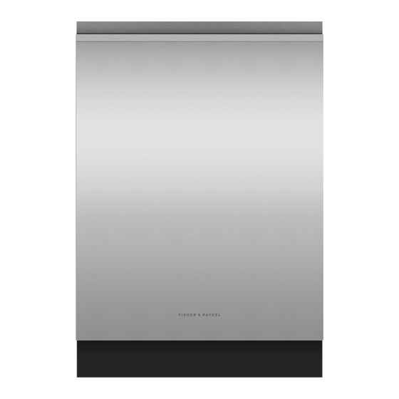
Summary of Contents for Fisher & Paykel DW24UNT4X2
- Page 1 BUILT-UNDER DISHWASHER CONTEMPORARY DW24UNT4X2 & DW24UNT2X2 models INSTALLATION GUIDE US CA 592980A 09.22...
-
Page 3: Safety And Warnings
SAFETY AND WARNINGS WARNING! WARNING! Electric Shock Hazard Cut Hazard Failure to follow this advice may result in Failure to use caution could result in injury. electrical shock or death. • Take care – panel edges are sharp. • This appliance must be earthed. This appliance requires a cord with an equipment-earthing WARNING! conductor and an earthing plug. -
Page 4: Installation
SAFETY AND WARNINGS WARNING! At the completion of the dishwasher installation, the Installer must perform the Final Checklist. To reduce the risk of fire, injury to persons or damage when using the appliance, follow the Remove all packaging materials supplied with the dishwasher. important safety instructions listed below. -
Page 5: Components Required
COMPONENTS REQUIRED PARTS Keep all packing materials until the unit has been inspected. Components for new installation only (available in hardware stores) Inspect the product to ensure there is no shipping damage. If any damage is detected contact the dealer or retailer you bought the product from to report the damage. Fisher &... - Page 6 COMPONENTS REQUIRED TOOLS Not supplied Powered driver Cross-head screw driver Flat-head screw driver Box cutter Allen Key 1/4" (6mm) and Nutdriver 1/4" (6.35mm) Adjustable wrench 6" Measuring tape 3/16" (4mm) and 5/16" (7.94mm) (152.4mm) Safety glasses Flashlight Gloves Bucket - for flushing the line Tubing cutter Hole saw set...
-
Page 7: Product Dimensions
PRODUCT DIMENSIONS PRODUCT DIMENSIONS INCH A Overall height* 33 3/4 – 36 1/8 857 – 917 B Overall width 23 7/16 C Overall depth 22 5/8 D Height of chassis 33 3/4 E Depth of chassis 20 1/2 F Height of feet* 0 – 2 3/8 0 – 60 PLAN G Depth of toe kick recess... - Page 8 CABINETRY DIMENSIONS CLEARANCES Connections can be located in an adjacent cabinet on either side of the dishwasher*** PLAN ISOMETRIC CABINETRY DIMENSIONS INCH CABINETRY CLEARANCES INCH A Minimum inside height* 33 3/4 A Minimum clearance to adjacent cupboard door 1/16 B Minimum inside width 23 5/8 B Minimum clearance to corner cupboard C Minimum overall depth**...
-
Page 9: Left Side
PLUMBING & ELECTRICAL CONSIDERATIONS Hose and cord lengths Your services can be installed to either the left-hand or right-hand side of the product in an adjacent cabinet. Refer to 'Cabinetry preparation' for service access requirements. The drain hose should not extend more than 13ft (4m). A longer drain hose will cause reduced performance. -
Page 10: Service Access
SERVICE ACCESS We recommend locating the service holes on either side of the dishwasher as shown. If the holes are created through wood, ensure the edges are smooth and rounded. If the holes are created through metal, ensure an edge protector is fitted. - Page 11 UNPACK PRODUCT CABINETRY PREPARATION Ensure all minimum cabinetry and Cut straps, lift carton off product and service specifications have been met remove the top cap. and that all services will be accessible Dispose of packaging responsibly. after installation. Ensure cabinetry floor is free from Remove the install kit, any internal bumps and obstructions that could packaging, all rubber bands and all tape.
- Page 12 SERVICES PREPARATION PUSH INTO CAVITY Using a flat bladed screwdriver, turn to Flush water line into a bucket. raise the leveling feet. Level the rear, Install a hand shut-off valve in a outside legs first followed by the front readily accessible location in the legs.
-
Page 13: Electrical Connection
ELECTRICAL CONNECTION INSTALL HARD PLUMBING Fitting copper pipe: Unscrew and remove the junction box Slide the compression nut and ferrule cover to access the terminal block. towards the end of the pipe. Insert the Do not remove the screw holding the end of the pipe into the elbow and junction box bracket in place. - Page 14 SECURE TO CAVITY PLUMBING & ELECTRICAL CONNECTION Ø1 1/2" (38MM) STANDPIPE INSTALLATION Loosely fit 2 x side fixing screws. Install the drain hose support to the back wall, as close to the underside of the countertop as possible. Refer to 'Plumbing &...
- Page 15 PLUMBING & ELECTRICAL CONNECTION SINK TRAP/WASTE TEE INSTALLATION SINGLE AIR GAP INSTALLATION Install the drain hose support to the back wall, as close to the underside of Install your single Air Gap Kit to the the countertop as possible. Refer to benchtop like shown.
-
Page 16: Installer Checklist
Ensure metal toe kick plate has been re-fitted. … If site is left without power after installation is complete, ensure water supply is turned off to prevent flooding. DW24UNT4X2 model shown. Refer to your User Guide for more information on your models functions. - Page 17 INSTALL METAL PLATE TOE KICK INSTALL TOE KICK CONTINUOUS TOE KICK PANEL Refit the toe kick and mounting plate panels. Slide the back of the mounting plate up or down to conceal any gaps left Align toe kick to product and ensure all between the product and floor.
- Page 18 FISHERPAYKEL.COM © Fisher & Paykel Appliances 2022. All rights reserved. The models shown in this guide may not be available in all markets and are subject to change at any time. The product specifications in this guide apply to the specific products and models described at the date of issue.


