Table of Contents
Advertisement
Quick Links
Advertisement
Chapters
Table of Contents
Troubleshooting

Related Manuals for Fluke OptiView III Series


Summary of Contents for Fluke OptiView III Series
- Page 1 Fluke Networks Optiview Workgroup Analyzer Specs Provided by www.AAATesters.com OptiView Series III Workgroup Analyzer Getting Started Guide PN 3105444 February 2008 © 2008 Fluke Corporation. All rights reserved. Printed in USA. All product names are trademarks of their respective companies.
- Page 2 Fluke Networks authorized resellers shall extend this warranty on new and unused products to end-user customers only but have no authority to extend a greater or different warranty on behalf of Fluke Networks. Warranty support is available only if product is purchased through a Fluke Networks authorized sales outlet or Buyer has paid the applicable international price.
- Page 3 Cryptix General License Note This Cryptix General License only applies to the data encryption software used by the OptiView remote user interface. Copyright © 1995-2008 The Cryptix Foundation Limited. All rights reserved. Cryptix is a trademark of The Cryptix Foundation Limited. Copyright ©...
-
Page 5: Table Of Contents
Safety Information ......................... 1 Cleaning the Analyzer ......................2 Has This Instrument Been Damaged in Shipping? ............... 2 Contacting Fluke Networks Sales, Service, and Support Centers ........2 OptiView Series III Workgroup Analyzer Support ............2 The Analyzer and Accessories ....................... 3 Supplied Out of the Box Items .................... - Page 6 OptiView Series III Getting Started Guide Software Update Procedure ....................16 Step One – Update the PC User Interface Software ............16 Step Two – Connect to the Analyzer via the Management Port ........17 Step Three – Run the User Interface Software ............18 Troubleshooting Your Analyzer ....................19 Before Calling Technical Support ..................19 Do you suspect the analyzer has locked up? ..............19...
-
Page 7: Before You Start
Before You Start Safety Information The following symbols are used on the product and in this document: NOT FOR CONNECTION TO PUBLIC TELEPHONE SYSTEMS PLEASE READ MANUAL FOR SAFETY COMPLIES WITH EUROPEAN UNION DIRECTIVE SHOCK HAZARD CLASS 1 LASER PRODUCT. DO NOT LOOK INTO LASER RECYCLE LITHIUM ION BATTERIES COMPLIES WITH CAN/CSA-C22.2 NO. -
Page 8: Cleaning The Analyzer
Contacting Fluke Networks Sales, Service, and Support Centers To order accessories or get the location of the nearest Fluke Networks distributor or service center, visit the Fluke Networks contact web site at www.flukenetworks.com/contact. Send email to support@flukenetworks.com. -
Page 9: The Analyzer And Accessories
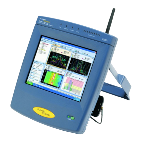
Workgroup Analyzer The Analyzer and Accessories The Analyzer and Accessories The analyzer is designed for troubleshooting and monitoring Local Area Networks (LANs). It tests all seven OSI layers from the cable to the application layer and everything in between, so problems have nowhere to hide. -
Page 10: Supplied Out Of The Box Items
Registration Card Fluke Networks can serve you best by registering online at www.flukenetworks.com. If you cannot register online, please fill out and return the supplied registration card. Startup Card... - Page 11 OPV-RPTR/PRO Analyzer to generate reports on the network to which the analyzer is connected. OptiView Protocol The Fluke Networks Windows based protocol analyzer for OPV-PE/PRO network engineers, LAN administrators, and network Expert technicians who maintain LANs. The application allows you to monitor and decode captured packets on your local network.
-
Page 12: About The Analyzer
OptiView Series III Getting Started Guide About the Analyzer General Specifications Analyzer Interfaces: 10/100/1000BASE-T (RJ-45), and 1000BASE-X and 100BASE-FX (SFP adapter) Analyzer LEDs: Management Link (in RJ-45 connector), Power, 10/100/1000/Fiber Link, Utilization, Transmit, Collision, and Errors Test Access: Active termination to a switch port, switch span port, or a hub Layer 2 Support: Ethernet Management Port: 10/100/1000BASE-T (RJ-45) Configuration Port: Serial RS-232 (9-pin male) -
Page 13: Connecting To The Management Port
Workgroup Analyzer About the Analyzer anj03f.eps Figure 2. Front View of the Analyzer Connecting to the Management Port Use the Management port to manage the analyzer out of band when it is connected to a different network (outside the network under test broadcast domain). In the event that you are unable to communicate with the analyzer through the Network 10/100/1000 or 1000BASE-X (fiber) ports, you can use the Management Port to gain access to the analyzer. -
Page 14: Security
User Interface button). It is also available for download at www.flukenetworks.com. To view decodes of the packets captured by the analyzer you need to purchase and install the Fluke Networks Protocol Expert software. Alternatively, the captured files can, in most cases, be imported into other 3 party protocol analysis software products. -
Page 15: Using The Optiview Tm Browser And User Interface Software
Workgroup Analyzer Accessing the Analyzer through the Remote User Interface Software Using the OptiView Browser and User Interface Software The OptiView Browser allows you access to OptiView Workgroup and OptiView Integrated analyzers through a browseable user interface installed on your PC. Double-click on an analyzer from this list and the user interface is launched. -
Page 16: Refresh Analyzer List
OptiView Series III Getting Started Guide Refresh analyzer list Re-displays the analyzer list with current active analyzers. Launch user interface for selected analyzer Launches the user interface software and connects to the selected analyzer. The selected analyzer is highlighted in the OptiView Browser device list or the IP address is entered in the OptiView Browser IP address field. -
Page 17: User Interface Events That Will Terminate A Remote Session
Workgroup Analyzer Accessing the Analyzer through the Remote User Interface Software User Interface Events that will Terminate a Remote Session The active TCP/IP session between the user interface software and the analyzer can be severed under the following conditions: IP parameters are manually changed on the analyzer and Apply is selected in the Management port TCP/ IP setup screen Note The following conditions only apply to the Network 10/100/1000 and 1000BASE-X... -
Page 18: Configuring The Analyzer Through The Serial Configuration Port
OptiView Series III Getting Started Guide Configuring the Analyzer through the Serial Configuration Port In situations where you do not have remote access (through the user interface software) to the analyzer, you may want to configure the analyzer IP address parameters for both the Network 10/100/1000 (or 1000BASE-X fiber) and Management ports before connecting the analyzer to a network. -
Page 19: Root Mode User Commands
Workgroup Analyzer Configuring the Analyzer through the Serial Configuration Port Root mode user commands: “management” Allows the user to enter “Management” configuration mode. This mode allows the user to configure IP parameters for the out-of-band Management Port. The text “/Management>” is appended to the prompt while in this mode. -
Page 20: Management Configuration Mode User Commands
OptiView Series III Getting Started Guide Management configuration mode user commands: “ipaddr A.B.C.D E.F.G.H” Statically assigns the IP address (A.B.C.D) and subnet mask (E.F.G.H) of the Management Port. Address and subnet mask are entered in decimal dot notation. Enables the automatic configuration of the Management Port “ipaddr dhcp”... -
Page 21: Using The Online Help System
Workgroup Analyzer Using the Online Help System “exit” Exits the Network configuration mode. Exiting will discard any Network port configuration changes unless ‘apply’ is entered. “show Displays the current value of an individual setup parameter of interest within the Network configuration mode. (user command)”... -
Page 22: Accessing And Navigating The Help System
OptiView Series III Getting Started Guide Setting up security - Setup | User Accounts and Setup | Remote Setting up community strings - Setup | SNMP and Setup | Agent Generating network traffic - Traffic Generator feature Capturing traffic passing over a network - Packet Capture feature Measuring bidirectional data flow –... -
Page 23: Accessing The Online Documentation
Resource CD that was shipped with your analyzer. To obtain additional CD copies or to get newer versions supplied to you on a CD rather than downloading from our web site, see the section on Contacting Fluke Networks Sales, Service, and Support Centers to make that request. -
Page 24: Step Two - Connect To The Analyzer Via The Management Port
OptiView Series III Getting Started Guide Step Two – Connect to the Analyzer via the Management Port Analyzer Management Port CAT5 patch cable PC NIC Card anj04f.eps Figure 5. Direct Management Port Connection Switch or Hub anj05f.eps Figure 6. LAN Management Port Connection... -
Page 25: Step Three - Run The User Interface Software
Workgroup Analyzer Updating the OptiView Workgroup Analyzer Firmware anj06f.eps Figure 7. Remote Management Port Connection Step Three – Run the User Interface Software When you launch the user interface software (an icon is placed on your desktop), the analyzer will automatically be listed in the OptiView Browser list as long as it is in the local network (broadcast domain). -
Page 26: Troubleshooting Your Analyzer
OptiView Series III Getting Started Guide Troubleshooting Your Analyzer Before Calling Technical Support Before calling technical support, you can perform these basic analyzer troubleshooting steps to pinpoint many problems: Do you suspect the analyzer has locked up? If yes, completely power-down the analyzer. IP Discovery or Tools results? Unexpected Does the analyzer have a valid IP address? Look at the Front Page screen OptiView button and see if a valid... -
Page 27: Safety And General Specifications
Workgroup Analyzer Safety and General Specifications Safety and General Specifications Table 3. General Specifications Weight 1.63 kilograms (3.6 lbs) Dimensions 4.1 x 21.1 x 32.8 cm (1.6 x 8.3 x 12.9 in), one half of a standard 19 in rack mount width AC input 85 to 265 VAC;... -
Page 28: Cable Type Specification
OptiView Series III Getting Started Guide Cable Type Specification Cable Types Unshielded Twisted Pair LAN cables (100 and 120 Ohm UTP category 3, 4, 5, 5E, and 6 ISO/IEC Class C and D) Foil-screened Twisted Pair cables (100 and 120 Ohm ScTP category 3, 4, 5, and 6 ISO/IEC Class C and D) Cable Length Measurable cable lengths are from 3 feet (.9 meter) to 500 feet (152 meters). - Page 29 Workgroup Analyzer Safety and General Specifications...
- Page 30 OptiView Series III Workgroup Analyzer Getting Started Guide PN 3105444 February 2008 © 2008 Fluke Corporation. All rights reserved. Printed in USA. All product names are trademarks of their respective companies.
- Page 31 Fluke Networks authorized resellers shall extend this warranty on new and unused products to end-user customers only but have no authority to extend a greater or different warranty on behalf of Fluke Networks. Warranty support is available only if product is purchased through a Fluke Networks authorized sales outlet or Buyer has paid the applicable international price.
- Page 32 Cryptix General License Note This Cryptix General License only applies to the data encryption software used by the OptiView remote user interface. Copyright © 1995-2008 The Cryptix Foundation Limited. All rights reserved. Cryptix is a trademark of The Cryptix Foundation Limited. Copyright ©...
- Page 34 Safety Information ......................... 1 Cleaning the Analyzer ......................2 Has This Instrument Been Damaged in Shipping? ............... 2 Contacting Fluke Networks Sales, Service, and Support Centers ........2 OptiView Series III Workgroup Analyzer Support ............2 The Analyzer and Accessories ....................... 3 Supplied Out of the Box Items ....................
- Page 35 OptiView Series III Getting Started Guide Software Update Procedure ....................16 Step One – Update the PC User Interface Software ............16 Step Two – Connect to the Analyzer via the Management Port ........17 Step Three – Run the User Interface Software ............18 Troubleshooting Your Analyzer ....................19 Before Calling Technical Support ..................19 Do you suspect the analyzer has locked up? ..............19...
-
Page 36: Before You Start
Before You Start Safety Information The following symbols are used on the product and in this document: NOT FOR CONNECTION TO PUBLIC TELEPHONE SYSTEMS PLEASE READ MANUAL FOR SAFETY COMPLIES WITH EUROPEAN UNION DIRECTIVE SHOCK HAZARD CLASS 1 LASER PRODUCT. DO NOT LOOK INTO LASER RECYCLE LITHIUM ION BATTERIES COMPLIES WITH CAN/CSA-C22.2 NO. -
Page 37: Cleaning The Analyzer
Contacting Fluke Networks Sales, Service, and Support Centers To order accessories or get the location of the nearest Fluke Networks distributor or service center, visit the Fluke Networks contact web site at www.flukenetworks.com/contact. Send email to support@flukenetworks.com. -
Page 38: The Analyzer And Accessories
Workgroup Analyzer The Analyzer and Accessories The Analyzer and Accessories The analyzer is designed for troubleshooting and monitoring Local Area Networks (LANs). It tests all seven OSI layers from the cable to the application layer and everything in between, so problems have nowhere to hide. -
Page 39: Supplied Out Of The Box Items
Registration Card Fluke Networks can serve you best by registering online at www.flukenetworks.com. If you cannot register online, please fill out and return the supplied registration card. Startup Card... - Page 40 OPV-RPTR/PRO Analyzer to generate reports on the network to which the analyzer is connected. OptiView Protocol The Fluke Networks Windows based protocol analyzer for OPV-PE/PRO network engineers, LAN administrators, and network Expert technicians who maintain LANs. The application allows you to monitor and decode captured packets on your local network.
-
Page 41: About The Analyzer
OptiView Series III Getting Started Guide About the Analyzer General Specifications Analyzer Interfaces: 10/100/1000BASE-T (RJ-45), and 1000BASE-X and 100BASE-FX (SFP adapter) Analyzer LEDs: Management Link (in RJ-45 connector), Power, 10/100/1000/Fiber Link, Utilization, Transmit, Collision, and Errors Test Access: Active termination to a switch port, switch span port, or a hub Layer 2 Support: Ethernet Management Port: 10/100/1000BASE-T (RJ-45) Configuration Port: Serial RS-232 (9-pin male) -
Page 42: Connecting To The Management Port
Workgroup Analyzer About the Analyzer anj03f.eps Figure 2. Front View of the Analyzer Connecting to the Management Port Use the Management port to manage the analyzer out of band when it is connected to a different network (outside the network under test broadcast domain). In the event that you are unable to communicate with the analyzer through the Network 10/100/1000 or 1000BASE-X (fiber) ports, you can use the Management Port to gain access to the analyzer. -
Page 43: Security
User Interface button). It is also available for download at www.flukenetworks.com. To view decodes of the packets captured by the analyzer you need to purchase and install the Fluke Networks Protocol Expert software. Alternatively, the captured files can, in most cases, be imported into other 3 party protocol analysis software products. -
Page 44: Using The Optiview
Workgroup Analyzer Accessing the Analyzer through the Remote User Interface Software Using the OptiView Browser and User Interface Software The OptiView Browser allows you access to OptiView Workgroup and OptiView Integrated analyzers through a browseable user interface installed on your PC. Double-click on an analyzer from this list and the user interface is launched. -
Page 45: Refresh Analyzer List
OptiView Series III Getting Started Guide Refresh analyzer list Re-displays the analyzer list with current active analyzers. Launch user interface for selected analyzer Launches the user interface software and connects to the selected analyzer. The selected analyzer is highlighted in the OptiView Browser device list or the IP address is entered in the OptiView Browser IP address field. -
Page 46: User Interface Events That Will Terminate A Remote Session
Workgroup Analyzer Accessing the Analyzer through the Remote User Interface Software User Interface Events that will Terminate a Remote Session The active TCP/IP session between the user interface software and the analyzer can be severed under the following conditions: IP parameters are manually changed on the analyzer and Apply is selected in the Management port TCP/ IP setup screen Note The following conditions only apply to the Network 10/100/1000 and 1000BASE-X... -
Page 47: Configuring The Analyzer Through The Serial Configuration Port
OptiView Series III Getting Started Guide Configuring the Analyzer through the Serial Configuration Port In situations where you do not have remote access (through the user interface software) to the analyzer, you may want to configure the analyzer IP address parameters for both the Network 10/100/1000 (or 1000BASE-X fiber) and Management ports before connecting the analyzer to a network. -
Page 48: Root Mode User Commands
Workgroup Analyzer Configuring the Analyzer through the Serial Configuration Port Root mode user commands: “management” Allows the user to enter “Management” configuration mode. This mode allows the user to configure IP parameters for the out-of-band Management Port. The text “/Management>” is appended to the prompt while in this mode. -
Page 49: Management Configuration Mode User Commands
OptiView Series III Getting Started Guide Management configuration mode user commands: “ipaddr A.B.C.D E.F.G.H” Statically assigns the IP address (A.B.C.D) and subnet mask (E.F.G.H) of the Management Port. Address and subnet mask are entered in decimal dot notation. Enables the automatic configuration of the Management Port “ipaddr dhcp”... -
Page 50: Using The Online Help System
Workgroup Analyzer Using the Online Help System “exit” Exits the Network configuration mode. Exiting will discard any Network port configuration changes unless ‘apply’ is entered. “show Displays the current value of an individual setup parameter of interest within the Network configuration mode. (user command)”... -
Page 51: Accessing And Navigating The Help System
OptiView Series III Getting Started Guide Setting up security - Setup | User Accounts and Setup | Remote Setting up community strings - Setup | SNMP and Setup | Agent Generating network traffic - Traffic Generator feature Capturing traffic passing over a network - Packet Capture feature Measuring bidirectional data flow –... -
Page 52: Accessing The Online Documentation
Resource CD that was shipped with your analyzer. To obtain additional CD copies or to get newer versions supplied to you on a CD rather than downloading from our web site, see the section on Contacting Fluke Networks Sales, Service, and Support Centers to make that request. -
Page 53: Step Two - Connect To The Analyzer Via The Management Port
OptiView Series III Getting Started Guide Step Two – Connect to the Analyzer via the Management Port Analyzer Management Port CAT5 patch cable PC NIC Card anj04f.eps Figure 5. Direct Management Port Connection Switch or Hub anj05f.eps Figure 6. LAN Management Port Connection... -
Page 54: Step Three - Run The User Interface Software
Workgroup Analyzer Updating the OptiView Workgroup Analyzer Firmware anj06f.eps Figure 7. Remote Management Port Connection Step Three – Run the User Interface Software When you launch the user interface software (an icon is placed on your desktop), the analyzer will automatically be listed in the OptiView Browser list as long as it is in the local network (broadcast domain). -
Page 55: Troubleshooting Your Analyzer
OptiView Series III Getting Started Guide Troubleshooting Your Analyzer Before Calling Technical Support Before calling technical support, you can perform these basic analyzer troubleshooting steps to pinpoint many problems: Do you suspect the analyzer has locked up? If yes, completely power-down the analyzer. IP Discovery or Tools results? Unexpected Does the analyzer have a valid IP address? Look at the Front Page screen OptiView button and see if a valid... -
Page 56: Safety And General Specifications
Workgroup Analyzer Safety and General Specifications Safety and General Specifications Table 3. General Specifications Weight 1.63 kilograms (3.6 lbs) Dimensions 4.1 x 21.1 x 32.8 cm (1.6 x 8.3 x 12.9 in), one half of a standard 19 in rack mount width AC input 85 to 265 VAC;... -
Page 57: Cable Type Specification
OptiView Series III Getting Started Guide Cable Type Specification Cable Types Unshielded Twisted Pair LAN cables (100 and 120 Ohm UTP category 3, 4, 5, 5E, and 6 ISO/IEC Class C and D) Foil-screened Twisted Pair cables (100 and 120 Ohm ScTP category 3, 4, 5, and 6 ISO/IEC Class C and D) Cable Length Measurable cable lengths are from 3 feet (.9 meter) to 500 feet (152 meters). - Page 58 Workgroup Analyzer Safety and General Specifications...