Advertisement
Quick Links
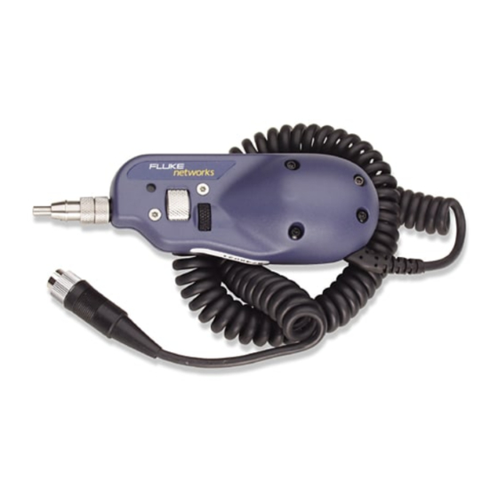
The OFTM-5352 FiberInspector Pro video probe connects to an OF-500 OptiFiber
tester to let you inspect the ends of fiber optic connectors. The probe's 250X and
400X magnifications reveal dirt, scratches, and other defects that can cause poor
performance or failures in fiber optic networks.
A FiberInspector Pro video probe comes with the following:
•
FT650 fiber probe
•
Probe adapter tips (ST, SC, FC, and universal 2.5 mm patch cord tip)
•
Adapter cable for the OF-500 OptiFiber camera connector
•
Instruction sheet
Registration
Registering your product with Fluke Networks gives you access to valuable
information on product updates, troubleshooting tips, and other support services.
To register, fill out the online registration form on the Fluke Networks website at
www.flukenetworks.com/registration.
PN 2114390 May 2004
© 2004 Fluke Corporation. All rights reserved. Printed in USA.
All product names are trademarks of their respective companies.
FiberInspector
OFTM-5352
Pro Video Probe
Instruction Sheet
Advertisement

Related Manuals for Fluke FiberInspector Pro OFTM-5352


Summary of Contents for Fluke FiberInspector Pro OFTM-5352
- Page 1 Registering your product with Fluke Networks gives you access to valuable information on product updates, troubleshooting tips, and other support services. To register, fill out the online registration form on the Fluke Networks website at www.flukenetworks.com/registration. PN 2114390 May 2004 ©...
-
Page 2: Safety Information
To verify that the option is enabled, press F on the tester; then select Enable . If the FiberInspector option is not shown as “INSTALLED” contact OptiFiber Options Fluke Networks for assistance. Using the Probe Figure 1 shows how to use the probe. Caution Some adapter tips have small screws that slide into a slot on the probe end. - Page 3 Focus Adapter tip control (match connector to be inspected) Magnification control IBER SETUP SAVE VIEW FUNCTIONS RECORDS FIBER EXIT INSPECTOR HELP ENTER TEST avr01.eps A Use the adapter cable provided to connect the probe to the video input jack on the side of the tester. B Screw an adapter tip that matches the connector type being inspected onto the fiber probe.
-
Page 4: Maintenance
Accessories The following accessories are available from Fluke Networks for the OFTM-5352 FiberInspector Pro video probe. Other styles of adapter tips may be available. Visit the Fluke Networks website for a complete list of fiber test accessories. Fluke Networks Description... -
Page 5: Specifications
Specifications Magnification 250X and 400X Camera type 0.33 in (8.38 mm) CCD with adjustable focus Light source Connection to OptiFiber 8-pin mini DIN to NTSC video port tester Power source Powered by the OF-500 OptiFiber tester Lighting technique Coaxial Dimensions 1.8 in x 1.7 in x 5.5 in (45.7 mm x 43.2 mm x 140 mm) (length depends on adapter tip) - Page 6 LIMITED WARRANTY & LIMITATION OF LIABILITY Fluke Networks products will be free from defects in material and workmanship for one year from the date of purchase. Parts, accessories, product repairs and services are warranted for 90 days. This warranty does not cover disposable batteries, cable...