
Related Manuals for Lorex SG17L7584


Summary of Contents for Lorex SG17L7584
-
Page 1: Instruction Manual
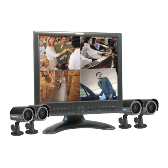
17" COLOR LCD DUAL QUAD SECURITY SURVEILLANCE SYSTEM WITH INTERNET REMOTE VIEWING Instruction Manual English Version 1.0 MODEL: SG17L7584 www.lorexcctv.com Copyright (c) 2006 LOREX Technology Inc. - Page 2 Thank you for purchasing the IP enabled 17” LCD 2 Page/8 Channel Color Quad Observation system. Lorex is committed to providing our customers with a high quality, reliable security product. The IP enabled Observation system allows you to make an ethernet LAN connection from the monitor to a router for internet monitoring.
-
Page 3: Important Safeguards
Important Safeguards In addition to the careful attention devoted to quality standards in the manufacture process of your video product, safety is a major factor in the design of every instrument. However, safety is your responsibility too. This sheet lists important information that will help to assure your enjoyment and proper use of the video product and accessory equipment. - Page 4 Important Safeguards Service 13. Servicing - Do not attempt to service this video equipment yourself as opening or removing covers may expose you to dangerous voltage or other hazards. Refer all servicing to qualified service personnel. 14. Conditions Requiring Service - Unplug this video product from the wall outlet and refer servicing to qualified service personnel under the following conditions.
-
Page 5: General Precautions
4. Keep enough space around the unit for ventilation. Slots and openings in the storage cabinet should not be blocked 5. During lightning storms, or when the unit is not used for a long time, disconnect the power supply, antenna, and cables to protect the unit from electrical surge LOREX TECHNOLOGY INC. http://www.lorexcctv.com General Precautions... - Page 6 Observation System Features Observation System Features • High Resolution 17" LCD Monitor with Network Interface for Remote Viewing over the internet* • Ultra Sharp image reproduction with High Contrast Ratio • Dual Quad Technology allows for viewing of up to 8 cameras •...
-
Page 7: Table Of Contents
Table of Contents Getting Started ... 8 SG17L7584 - Front - Primary Function Buttons ... 9-12 SG17L7584 - Front - Secondary Function Buttons ... 13 SG17L7584 - Back ... 14-15 Remote Control ... 16 Installing Cameras ... 17 Connecting Cameras ... 18 Monitor Features ... -
Page 8: Getting Started
Getting Started Getting Started The SG17L7584 system comes with the following components: 17” Color 2 Page / 8 Channel Dual 4 x 1/4” CCD Color IR Day/Night Quad LCD Monitor Cameras (with Removable Sunshade) 4 x Camera Ethernet Standard Power Cable Cables (57’... -
Page 9: Sg17L7584 - Front - Primary Function Buttons
SG17L7584 - Front - Primary Function Buttons 1. FN (FUNCTION) BUTTON - When this button is pressed, the LED below the button will turn ON indicating that secondary function of the front panel buttons can be activated. To de-activate the secondary function for the buttons (and reactivate the primary functions), press the button [FN] button again and the LED will turn off. - Page 10 SG17L7584 - Front - Primary Function Buttons 4. FRZ ALL BUTTON - The function of the FRZ ALL (Freeze All) button is to digitally freeze the image that is being displayed on the monitor. To freeze an image: • Press the [FRZ] button while viewing a FULL SCREEN single camera in live video. This will freeze the camera image being viewed.
- Page 11 9. VCR / DVR BUTTON - Changes the display from the Live Mode Camera inputs to the DVR/ VCR Audio/Video playback and recording unit. To return to the normal viewing of the Camera inputs, press [VCR] button again. SG17L7584 - Front - Primary Function Buttons ] keys to move the area being captured in 2x ZOOM...
- Page 12 SG17L7584 - Front - Primary Function Buttons 10. PIP POP BUTTON - Display a main camera image with secondary camera sub-images: • PIP (Picture In Picture) allows you to view three locations simultaneously, one being the main channel, the others being viewed as small images on the screen.
-
Page 13: Sg17L7584 - Front - Secondary Function Buttons
NOTE: Accessory PTZ Camera model SG7380 is required to operate this feature. 17. IR RECEIVER - Infrared receiver for optional Remote Control 18. MIC - Enable TWO-WAY AUDIO with select LOREX cameras 19. MAIN BUTTON - Pressing the Main button while in the PIP, Dual PIP or POP mode will change the camera input of the main screen being displayed. -
Page 14: Sg17L7584 - Back
SG17L7584 - Back SG17L7584 - Back 1. RCA AUDIO INPUTS - Channel 1-8 Audio inputs (for non-DIN type cameras with standard RCA Audio output). 2. BNC VIDEO INPUTS - Channel 1-8 camera inputs (used to connect Cameras with BNC connection type), or can be used for Looping Video Output to a DVR... -
Page 15: Sg17L7584 - Back
SG17L7584 - Back Additional controls can be accessed by tilting the monitor forward. 1. AC INPUT - Connect the AC power (using the power cord provided with the unit) from the monitor to an electrical outlet 2. POWER SWITCH - This button controls power to the entire unit. Depress the side with the ‘I"... -
Page 16: Remote Control
Remote Control Remote Control Listed below is a quick reference for the Remote Control. For details on specific features, refer to the SG17L7584 - Primary / Secondary Buttons on Pages 10-14. -
Page 17: Installing Cameras
Installing Cameras The SG17L7584 Observation System includes 4 - 1/4” CCD Color IR Day/Night Indoor/Outdoor Cameras* INFRA-RED LEDs - Provides illumination for low light conditions CAMERA LENS - Delivers CCD Color image to the Observation System using a 6mm lens... -
Page 18: Connecting Cameras
Connecting Cameras Connecting Cameras The SG17L7584 Observation System includes 4 x 1/4” Color CCD DIN Cameras. Additional cameras can be added to the 4 additional camera inputs using the DIN or BNC ports. DIN Connected Cameras 4 x 1/4” COLOR CCD DIN cameras are included with the Observation System. -
Page 19: Monitor Features
Monitor Features The SG17L7584 Observation System has adjustable tilt and height positioning. The height can be adjusted using the thumbscrews at the base. • Loosen the thumbscrews (located on the lower left and right sides of the base) • Adjust the Monitor to the desired height •... -
Page 20: Cable Channel
Cable Channel Cable Channel The SG17L7584 Observation System comes with a built in cable channel to easily organize and conceal wiring. 1. Remove the Cable Channel Cover. 2. Connect the Power Cable, Cameras, Ethernet Cable and any Alarm Devices to the System by running the cables through the hole in the stand before connecting to the Observation System. -
Page 21: Main Menu Control
Main Menu Control Enter the MENU screen by pressing the MENU button. Scroll through the 9 options by pressing the UP and DOWN buttons. To enter a sub-menu, navigate to the option and press the OK button. To exit a SUBMENU, select the RETURN option (and press the OK button) which takes you back to the MAIN MENU. -
Page 22: Time / Date Set
Time / Date Set Time / Date Set This submenu allows you to change the TIME and DATE displayed on the monitor (On Screen Display), and recorded through an optional DVR / VCR. 1. DISP MON - Display the DATE / TIME on the monitor screen. -
Page 23: Sequence Set
Sequence Set This submenu allows you to change the length of time a camera is displayed while the SEQUENCE (SEQ) feature is enabled. When in SEQUENCE mode, the observation monitor cy- cles through available cameras in the sequence shown below. NOTE: If a camera is set to 0 SEC, it will be skipped in the AUTO SEQUENCING. -
Page 24: Pip/Pop Set
PIP/POP Set PIP/POP Set This submenu allows you to change the settings for PIP (Picture IN Picture) and POP (Picture ON Picture). PIP displays small viewing screen(s) superimposed onto the larger main viewing screen,. POP displays small viewing screen(s) along the top or bottom of the larger main viewing screen. 1. -
Page 25: Title Set
4. RETURN - Return to the MAIN MENU. Navigate by pressing the buttons to highlight, and press the OK button to select 5. EXIT - Return to the camera view. Navigate by pressing the buttons to highlight, and press the OK button to select Title Set This submenu allows you to change the displayed description of the camera (8 character max.). -
Page 26: Alarm Set
Alarm Set This submenu allows you to configure the ALARM alert type and duration.This alarm type is used in conjunction with external alarm input terminals. PIR cameras are offered by LOREX, but are not included with this system. 1. ALARM - Configures the ALARM type for an alarm event. -
Page 27: Motion Set
Motion Set This submenu allows you to change the configurations for MOTION detection, using the monitors built-in Pixel Based Motion Detection. 1. MOTION - Sets the motion detection alarm mode. Navigate by pressing the highlight, and press the OK button to switch between MOTION alarm modes: •... -
Page 28: Motion Set
Motion Set 4. AREA - Sets the area for motion detection. Navigate by pressing the highlight, and press the OK button to set the MOTION detection area. Selections include: [01] [03] [05] 5. RETURN - Return to the MAIN MENU. Navigate by pressing the buttons to highlight, and press the OK button to select... -
Page 29: System Set
System Set This submenu allows you to change the general preferences for the OBSERVATION SYSTEM. 1. KEY BUZZER - Sets the audible BUZZER that can be heard when pressing any key to ON or OFF. Navigate by pressing the highlight, and press the OK button to select Y or N. 2. - Page 30 System Set 7. PAN/TILT - Adjust the Pan / Tilt of the camera (PTZ cameras only). Select Y if a PTZ camera is connected. 8. ALARM OUT - Set to N/O (Normally Open) or set to N/C (Normally Closed). 9. DEFAULT SET - Set to Y to reset the unit to factory defaults upon exiting the menu 10.
-
Page 31: Monitor Set
Monitor Set This submenu allows you to change the picture settings for the OBSERVATION SYSTEM MONITOR. 1. CONTRAST - Adjust the image contrast. Navigate by pressing the buttons to highlight, and press the OK button to select. Press the buttons to change the CONTRAST (maximum of 63). -
Page 32: Netviewer - Installation Requirements
NetViewer - Installation Requirements NetViewer - Installation Requirements The NetViewer software (included with the Observation System) has the following installation requirements. Minimum System Requirements: Operating System Processor .Pentium 4 - 1.5 GHz Processor (or equivalent) Memory Hard Drive Recommended System Requirements: Operating System Processor Memory... -
Page 33: Network Connectivity
Network Connectivity The SG17L7584 Observation System can be remotely controlled using your existing network and the provided NetViewer software. 1. Connect the Observation System to the Router using the supplied Ethernet Cable. Power Observation unit on. You may need to tilt the monitor forward to access the Ethernet Port. -
Page 34: Setting Up Your Ddns Account
Setting Up Your DDNS Account Lorex offers a free DDNS server for use with your System. A DDNS account allows you to set up a web site address that points back to your Local Network. The following outlines how to set up your free DNS account. -
Page 35: Setting Up Your Ddns Account
4. Complete the System Information fields as follows: • Product License: Select your product model from the Product License drop down menu • <Product Code> - <MAC Address>: Locate the MAC address of your (recorded while loading the System) • URL Request: Choose a URL for your DDNS connection (i.e. your name, your company or business name, or anything of your choice.) NOTE: The URL request must not exceed 8 CHARACTERS... -
Page 36: Using The Lorex Ipedit Application
3. Double -click the application to run 4. A list of all detected Lorex Network Devices will be shown. Click on the name of the device on the MONITOR LISTS section (left side) to populate the device data on the right side list 5. -
Page 37: Router Port Forwarding
Router Port Forwarding How do I enable Port Forwarding on my Router? You will need to enable port forwarding on your Router to allow for external communications with your Observation System. Computers, Observation Systems, and other devices inside your network can only communicate directly with each other within the internal network. -
Page 38: Troubleshooting
Troubleshooting Troubleshooting When a malfunction occurs, it may not be serious and can be corrected easily. The following describes the most common problems and solutions. Please refer to the following before calling your Observation System dealer Problem: Observation System Unit is not receiving power, or is not powering up Check: •... -
Page 39: Troubleshooting
Problem: The image on the Observation System is too dark or too bright Check: • Adjust the CONTRAST and BRIGHTNESS of the unit (Refer to the Menu section) Problem: The image on the Observation System appears, but does not have sound Check: •... -
Page 40: Observation System Specifications - Appendix #1
Observation System Specifications - Appendix #1 Observation System Specifications - Appendix #1 Display Pixels (H x V) Pixel Arrangement Pixel Pitch White Luminance Contrast Ratio Camera Capable Quad Speed Camera Input Alarm Inputs / Outputs Input Signal Power Source Power Consumption Operating Temperature Color 17”... -
Page 41: Camera Specifications - Appendix #2
Operating Temp Weather Proof Rating Operating Humidity As our products are subject to continuous improvement, LOREX Technology Inc. and its subsidiaries reserve the right to modify product design, specifications and prices, without notice 1/4" Interline transfer type color CCD 512 H x 492 V (252k PIXELS) -
Page 42: Connecting To A Single Channel Dvr / Vcr - Appendix #3
Connecting to a Single Channel DVR / VCR - Appendix #3 Connecting to a Single Channel DVR / VCR - Appendix #3 The SG17L7584 Observation System can be used with a Single Channel DVR or VCR unit (not included) 1. Connect the Video cable from the... -
Page 43: Connecting To A Multi-Channel Dvr - Appendix #4
Connecting to a Multi-Channel DVR - Appendix #4 The SG17L7584 Observation System can be used with a Multi-Channel DVR (not included). A Multi-Channel DVR enables you to record multiple video streams with a single device NOTE: The CH1 - CH8 BNC Video in-... -
Page 44: Connecting A Slave Monitor - Appendix #5
Connecting a Slave Monitor - Appendix #5 Connecting a Slave Monitor - Appendix #5 Connections to a Slave Monitor (not included) can be made through the SLAVE OUT ports on the back of the Observation System A Slave Monitor is used as a View Only device. -
Page 45: Connecting Motion / Alarm Device - Appendix #6
Connecting Motion / Alarm Device - Appendix #6 Motion detection and Alarm controls are enabled through the Menu system on the Observation System. Additional motion sensor devices can be connected to the system (Motion Sensors, Door/Window Sensors). A motion detection or sensor unit can be used to send a signal to the Observation System to begin camera viewing on the matching Video... -
Page 46: Full Connectivity Diagram - Appendix #7
Full Connectivity Diagram - Appendix #7 Full Connectivity Diagram - Appendix #7 The following diagram outlines a general set of connections available with the SG17L7584 Observation System. OBSERVATION SYSTEM SENSOR (Not Included) (Not Included) ROUTER (Not Included) 4 x 1/4” CCD CAMERAS... -
Page 47: Optional Accessories
Optional Accessories The following accessories are available to add to your existing system CABLE Extends the length between the CAMERA and MONITOR. Available in 65’, 100’ and 250’ lengths OBSERVATION CAMERAS Accessory PIR motion sensor observation system camera TO ORDER THESE ACCESSORY ITESMS OR FOR A COMPLETE LISTING OF AVAILABLE PRODUCTS, PLEASE VISIT US ON THE WEB AT: DVR UNIT Accessory DVR units - Record... - Page 48 Optional Accessories...
- Page 49 It’s all on the web Product Information User Manuals Quick Start Guides VISIT www.lorexcctv.com Strategic Vista International Inc. Specification Sheets Software Upgrades Firmware Upgrades wwwlorexcctv.com...