Lorex SG17LD800 Series Instruction Manual
Lcd monitor / 8 channel dvr combo
Hide thumbs
Also See for SG17LD800 Series:
- Instruction manual (102 pages) ,
- Frequently asked questions manual (8 pages) ,
- Installation manual (8 pages)
Table of Contents
Advertisement
LCD MONITOR / 8 CHANNEL
DVR COMBO
Instruction Manual
English Version 3.0
SERIES:
SG17LD800 & SG19LD800
www.lorexcctv.com
Series Includes: SG17LD800 & SG19LD800 Series (NTSC); SG17LD800P & SG19LD800P Series
(PAL); SG17LD804-161 & SG19LD804-161; SG17LD804P-161 & SG19LD804P-161
©
Copyright
2007 LOREX Technology Inc.
Advertisement
Table of Contents

Related Manuals for Lorex SG17LD800 Series


Summary of Contents for Lorex SG17LD800 Series
- Page 1 LCD MONITOR / 8 CHANNEL DVR COMBO Instruction Manual English Version 3.0 SERIES: SG17LD800 & SG19LD800 www.lorexcctv.com Series Includes: SG17LD800 & SG19LD800 Series (NTSC); SG17LD800P & SG19LD800P Series (PAL); SG17LD804-161 & SG19LD804-161; SG17LD804P-161 & SG19LD804P-161 © Copyright 2007 LOREX Technology Inc.
- Page 2 Thank you for purchasing the LCD / 8 Channel DVR Combo. Lorex is committed to providing our customers with a high quality, reliable security product. This system offers a whole new level of security surveillance to the consumer market. Combining the...
- Page 3 Important Safeguards Important Safeguards In addition to the careful attention devoted to quality standards in the manufacture process of your video product, safety is a major factor in the design of every instrument. However, safety is your responsibility too. This sheet lists important information that will help to assure your enjoyment and proper use of the video product and accessory equipment.
- Page 4 Important Safeguards Service 13. Servicing - Do not attempt to service this video 19. Cleaning - Unplug the video product from the wall equipment yourself as opening or removing covers outlet before cleaning. Do not use liquid cleaners or may expose you to dangerous voltage or other aerosol cleaners.
- Page 5 4. Keep enough space around the unit for ventilation. Slots and openings in the storage cabinet should not be blocked 5. During lightning storms, or when the unit is not used for a long time, disconnect the power supply, antenna, and cables to protect the unit from electrical surge LOREX TECHNOLOGY INC. http://www.lorexcctv.com...
- Page 6 • Browser Based Remote Client: View and control your DVR from any internet connected PC with Internet Explorer (does not require Lorex Client software). • Universal Camera Inputs: Supports Lorex proprietary 6 PIN DIN or any professional grade camera • Spot Video Out: Allows the user to connect another monitor to the system and display selected video channels in another location.
-
Page 7: Table Of Contents
Table of Contents Table of Contents Getting Started ..................9 Front Panel ..................10-13 Rear Panel ..................14-15 Remote Control ..................16 MC7520 Cameras ................... 17 Camera Installation ................18-19 Display Modes ................... 20-22 PTZ (Pan/Tilt/Zoom) & Focus Controls ........... 23 System Power Off ................... - Page 8 System Specifications ....................... 69 MC7520 Camera Specifications - Appendix #2 ........70 Lorex Client Software Requirements - Appendix #3 ....... 71 Connecting a Slave (Spot-Out) Monitor - Appendix #4 ......72 Connecting Motion / Alarm Device - Appendix #5 ........73 Connecting PTZ Cameras - Appendix #6 ..........
-
Page 9: Getting Started
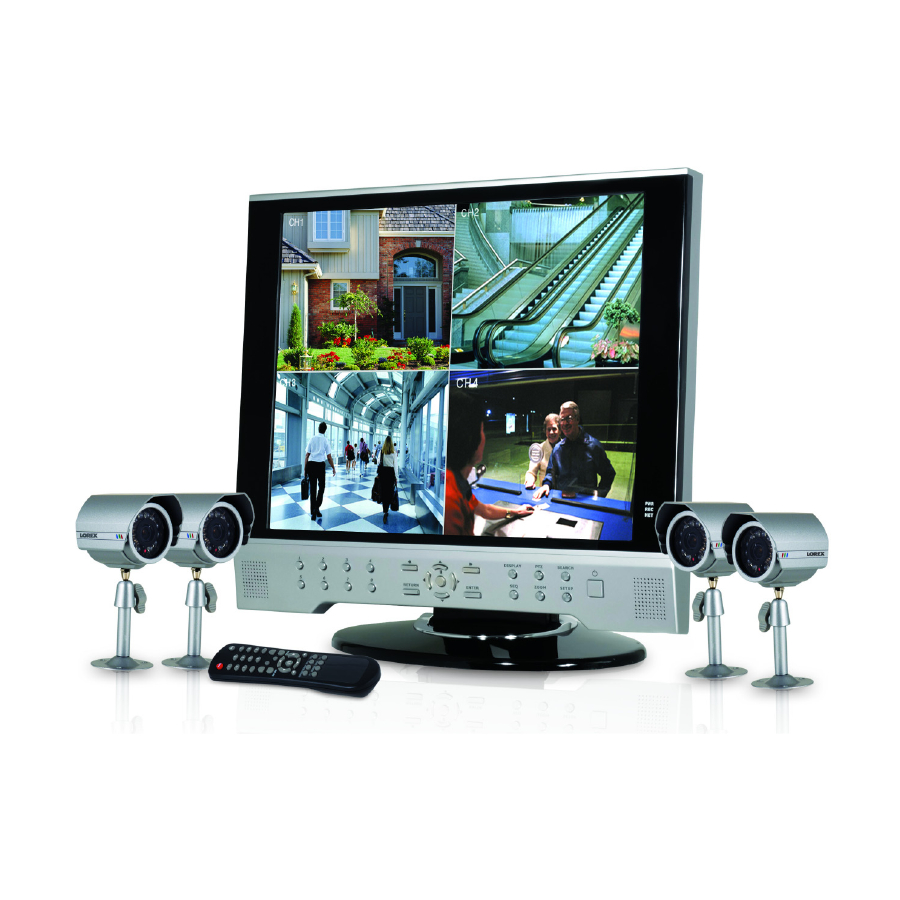
Getting Started Getting Started The system comes with the following components: 4 x CAMERAS WITH LCD & DVR COMBO UNIT STANDS WITH INSTALLED 160 GB POWER ADAPTER 4 x 100 FT. (30M) EXTENSION CABLES REMOTE ETHERNET HARDWARE & SOFTWARE CONTROL CABLE MANUALS &... -
Page 10: Front Panel
Front Panel Front Panel 1. REW BUTTON - Reverses the playback of the currently displayed Video 2. FF BUTTON - Fast forwards the playback of the currently displayed Video 3. DISPLAY - Changes the onscreen Camera display: • Single - Displays a single camera onscreen •... - Page 11 NOTE: PTZ option will only work with PTZ type cameras (not provided with this unit). Visit the Lorex website at http://www.lorexcctv.com for a full range of Pan/Tilt/Zoom Cameras. 5. SEARCH BUTTON - Opens the Search Menu to view previously recorded data. Refer to page 25 for detailed search options.
- Page 12 Front Panel 8. CHANNEL SELECT BUTTONS - Displays individual camera views. Also used to input the system Password when accessing the Setup Menu. 9. RETURN BUTTON - • Returns to a previous screen in Menu Mode. • Exits from Menu Setup (when in the Main Menu screen). Exits from Search and PTZ Modes. 10.
-
Page 13: Front Panel
Front Panel 12. SEQ BUTTON - Used to Sequence between all camera locations in Full Screen mode (in sequential order). To exit Sequence Mode, Press the SEQ button again 13. ZOOM BUTTON - This monitor is equipped with digital ZOOM. To utilize this feature proceed as follows: •... -
Page 14: Rear Panel
Rear Panel Rear Panel 1. 6 PIN DIN CAMERA INPUTS - Channel 1-8 Camera inputs (for cameras with 6 Pin DIN connections). DIN type cameras are provided with the System. Cameras with 6 Pin DIN connections draw power from the System - additional power adapters are not needed. -
Page 15: Rear Panel
Rear Panel 4. SPOT OUT - Video Output port to connect the unit to a secondary DVR or TV 5. AUDIO OUT - Audio Output port to connect the unit to a secondary DVR or TV 6. ALARM FUNCTION TERMINALS (INPUT/OUTPUT) - These terminals are used to connect external alarm devices such as a motion sensor, door/alarm sensor, or time lapse VCR for Alarm Recording. -
Page 16: Remote Control
Remote Control Remote Control Listed below is a quick reference for the Remote Control. POWER BUTTON - SETUP BUTTON - Turns the system power Opens the Main Menu ON/OFF (system setup) REMOTE ID* - CHANNEL BUTTONS - Configure when using Press select multiple systems.*... -
Page 17: Mc7520 Cameras
MC7520 Cameras MC7520 Cameras The System includes 4 CCD Color IR Day/Night Indoor/Outdoor Cameras* INFRA-RED LEDs - Provides illumination for low light conditions CAMERA LENS MICROPHONE - Picks up sound near the camera and transmits to the System (located on the rear of the camera). -
Page 18: Camera Installation
Camera Installation Camera Installation Before you install the camera, carefully plan where and how you will position the camera, and where you will route the cable that connects the camera to the System. Installation Warnings: • Select a location for the camera that provides a clear view of the area you want to monitor, which is free from dust, and is not in line-of-sight to a strong light source or direct sunlight. -
Page 19: Camera Installation
Camera Installation Connecting Cameras 1. Connect the female end of the supplied 100’ extension’ cable to the camera. NOTE: Confirm that the arrows on the DIN Camera Cable and the DIN Extension cable are pointed together when connecting the cable. If the pins in the DIN Cable are bent, the Camera will NOT function. -
Page 20: Display Modes
Display Modes Display Modes Initial Loading Sequence • Press the POWER button located on the front panel of the Observation System to start the unit. • The System will perform a Hard Drive check NOTE: This unit includes a 160GB Hard Drive. •... - Page 21 Display Modes Network Connectivity Indicator The Network Indicators appear when a remote connection is made to the unit via the Remote Agent software, or through the Internet Explorer Web Client: • Green: Indicates that the network connection is stable. • Blue: Indicates that the network connection experiencing difficulties.
- Page 22 Display Modes Zoom Mode • Displays the Camera in ZOOM Mode. • Use the Arrow keys to adjust the Zoom location. • Press the Return key to exit ZOOM Mode. Covert Camera Mode • Displays the Camera in Covert Mode. •...
-
Page 23: Ptz (Pan/Tilt/Zoom) & Focus Controls
PTZ (Pan/Tilt/Zoom) & Focus Controls PTZ (Pan/Tilt/Zoom) & Focus Controls The PTZ / Focus Menus will only work with PTZ type cameras (not included): PTZ Control Screen Focus Control Screen Press the PTZ Button on the front panel of Press the PTZ Button a second time to the system, or on the Remote Control to access the Focus Control Screen: access the PTZ Control Screen:... -
Page 24: System Power Off
System Power Off System Power Off Monitor Display Shutoff • Press the Power Button on the front panel or remote control for one second to turn off the monitor only. • The System will continue to record while the monitor is off. •... -
Page 25: Search Mode
Search Mode Search Mode Search mode allows you to locate previously recorded video by Date and Time, or by Event Type. • Press the Search Button on the front panel or Remote Control • Enter the User Name and Password (if required). -
Page 26: Search By Event
Search Mode Search By Event Searches the system based on Event Type (Alarm, Motion, Continuous or System). • Press the right arrow button on the front panel or remote control to access the Search By Event screen. • Select From and To dates, Events (Alarm, Continuous, Motion and Other) and Cameras •... -
Page 27: Menu Navigation Controls & Tips
Menu Navigation Controls & Tips Menu Navigation Controls & Tips Menu Navigation Controls Navigation Controls - Move Up/Down/Left/Right. Enter Button - Press this button to select and change the values in a menu option. Return Button - Complete modifications of a menu option; exit a menu Virtual Keyboard Control The Virtual Keyboard control becomes available when keyboard input is needed for entering information such as... -
Page 28: System Setup Controls
System Setup Controls System Setup Controls • Enter the MENU screen by pressing the MENU button. Enter the password (if required), and select the SYSTEM SETUP option. • Scroll through the 6 options by pressing the UP, DOWN, LEFT and RIGHT buttons on the Front Panel or Remote Control. -
Page 29: Display Menu
Display Menu Display Menu The Display Menu controls: OSD - Onscreen display settings control the camera titles, event indicators, and general screen settings. MONITOR - Display settings for Alarm and Events SEQUENCE - Controls for the display of video images in Sequence Mode SPOT-OUT - Sends camera video to a secondary monitor (by individual camera based on Menu Settings) through the... -
Page 30: Monitor
Display Menu OSD (Onscreen Display) • Motion Sensor Display - Turns the display of the Motion Sensor to: - Active: Display motion sensor of motion detection area. - Inactive: Display motion sensor except motion detection area. - Off: No display of motion sensor. •... -
Page 31: Sequence
Display Menu SEQUENCE Sets the Sequence Mode for the display of available channels. • Activation - Turns the Sequence ON/ OFF. NOTE: Up to 16 different Sequence Mode settings can be configured, however only ONE can be active at a time. •... -
Page 32: Sequence Setup Mode
Display Menu SEQUENCE SETUP MODE 1. Press the ENTER button. Setup 2. Select the Display Mode (5 Mode is active. different Display Options - Single, Quad, 6, 8A & 8B). 3. Press the Number Keys to Select 4. Choose the next Display Mode (up channels to be displayed in to 16 additions). -
Page 33: Spot-Out
Display Menu SPOT-OUT Sends the Specified camera video to a secondary Monitor (via the Spot Out Port on the back of the unit). • Check or Uncheck the selected Cameras to have the video sent to a Secondary Monitor in Sequence. NOTE: Any cameras NOT checked will not be sent as video to the Spot Out Monitor. -
Page 34: Camera Menu
Camera Menu Camera Menu The Camera Settings and Controls: CAMERA TITLE - Settings for the onscreen display of individual Camera Titles. COLOR SETUP - Color settings for individual cameras. PTZ SETUP - Configuration for PTZ type cameras (not included with the system). MOTION SENSOR - Configuration for Video Motion Detection. -
Page 35: Color Setup
Camera Menu COLOR SETUP Displays the settings for Brightness, Contrast, Tint and Color for individual cameras. • Press the ENTER Button and select a camera. • Set the Brightness, Contrast, Tint and Color for each camera. These settings range 1(low)~100(high) •... -
Page 36: Ptz Properties
Camera Menu PTZ PROPERTIES • Channel No. - Camera Number. • PTZ Driver - The compatible driver selected for the PTZ Camera. • Auto Focus - Sets the Automatic camera focus to ON/OFF. • Auto Iris - Sets the Automatic Shutter to ON/OFF. -
Page 37: Sound Menu
Sound Menu Sound Menu The System Sound settings: AUDIO - Settings for the system Audio for Live and Remote monitoring. BUZZER - Settings for System Buzzer (audible alerts). SOUND • Live Audio - Turns Live System Audio (from the Audio on the terminal) to ON/ OFF. -
Page 38: System Menu
System Menu System Menu The System Setting controls contain: DATE/TIME - Date and Time controls for the system. NETWORK - Network and remote access controls. MAIL - Mail setup USER MANAGEMENT - Controls for system users. SYSTEM MANAGEMENT - System specific settings and controls CONTROL DEVICE -? DATE/TIME... -
Page 39: Network
Information will need to be assigned manually. • DDNS (Dynamic DNS) - Allows the System to be accessed using a fixed domain (website URL) without entering the IP address. Lorex offers a free DDNS Service http:// ddns.strategicvista.net If you use the DDNS, there is no need to enter the IP Address with every connection. -
Page 40: Network
IP address of the local DNS Server (i.e. local Router). • DDNS Server - Set to the free DDNS Server provided Lorex (ddns.strategicvista.net). • Net Client Port - Default port of 6100. Used for remote connection. • Web Server Port - Default port of 80. -
Page 41: User Management
System Menu USER MANAGEMENT • User setup consists of 3 groups: Administrator, Manager or User. • Up to 7 new users can be added to the system. • ADD - Opens the ADD New User screen to configure the new user settings NOTE: A maximum of 4 users can be remotely connected to the System simultaneously. -
Page 42: System Management
System Menu SYSTEM MANAGEMENT • System Information - Navigate to the PRESS button, and choose ENTER to display the System Information. • System Name - Input a name for the system using the Virtual Keyboard. • FW Update - Navigate to the PRESS button, and choose ENTER to update the System Firmware. - Page 43 System Menu SYSTEM MANAGEMENT Firmware Update New firmware is periodically available for download from the www.lorexcctv.com website. The firmware on the unit can be updated via the USB Port: • Download the new firmware from the website. Copy the files from the PC to the USB Memory Stick.
-
Page 44: Control Device
System Menu SYSTEM MANAGEMENT Factory Defaults The System can be returned to the Factory default settings: • Select the ‘Factory Defaults’ option by selecting the PRESS button. • Choose OK to reset the unit, or CANCEL to exit without resetting. NOTE: If the System is reset to Factory Defaults, all settings will be lost (except the Date and Time). -
Page 45: Event / Sensor
Event / Sensor Event / Sensor The Event Sensor Setting controls contain: HDD EVENT - Checks the Hard Drive for errors. ALARM IN - Configuration settings for an external Alarm sensor (i.e. Door / Window Sensors). ALARM OUT - Sends a signal to an external device when an alarm is detected. -
Page 46: Alarm Input
Event / Sensor ALARM INPUT Configurations for any external alarm device (i.e. a Door or Window Sensor). Refer to page 73 for hardware configuration details. • Operation - Sets the Alarm Sensor Connection Status (Enable / Disable) for an external alarm (i.e. Door or Window Sensors). -
Page 47: Buzzer Out
Event / Sensor ALARM OUT • Duration - Sets the Reacted Relay Time. (5sec~5min or Until key-in) • HDD Event - Turns the Alarm ON/OFF when the Hard Drive experiencing problems. • Alarm - Sends the Alarm Out when an Alarm Event is detected (set to ON/ OFF). -
Page 48: Email Notification
Event / Sensor EMAIL NOTIFICATION • Notification - Sets the E-Mail notification ON/OFF. • HDD Event - A notification is sent if a Hard Drive event is detected (set to ON/ OFF). • Notifications can be enabled for each channel for: Alarm Video Loss Motion can be selected... -
Page 49: Disk Management
Disk Management Disk Management • Record Time Limit - Setup for the Recording Time Limit (between 12 hours ~1 month) NOTE: The Record Time Limit refers to the length of time data will be kept on the drive. For example: The Record Time Limit is set to 7 days. -
Page 50: Recording Menu Controls
Recording Menu Controls Recording Menu Controls • Enter the RECORDING MENU screen by pressing the MENU button. Enter the password, and select the RECORDING MENU option. • Scroll through the 3 options by pressing the UP, DOWN, LEFT and RIGHT buttons on the Front Panel or Remote Control. -
Page 51: Recording Operations
Recording Menu Controls Recording Operations • RECORDING MODE - Changes the Recording mode from Simple Advanced (see below). • SCHEDULE MODE- Sets the Scheduled Recording Mode to Daily or Weekly. • PRE EVENT RECORDING - When an alarm is detected, the Pre Alarm will begin recording before the Alarm was detected (retrieved from video cache). -
Page 52: Simple Recording Mode
Simple Recording Mode Simple Recording Mode • Recording Quality - Sets the video recording quality to Low, Standard, High or Highest. • Recording Size - Sets the video capture size for all camera to 352x240, 704x240 or 704x480. • FPS - Sets the Frames Per Second for recording across all channels. -
Page 53: Advanced Recording Mode
Advanced Recording Mode Advanced Recording Mode Continuous / Motion Setup • PARAMETER MODE - Contains the general recording parameters for each camera • SCHEDULE MODE - Contains the schedule recording settings for each camera. NOTE: Audio Recording ONLY works on Channels 1~4. -
Page 54: Continuous / Motion Schedule Mode
Advanced Recording Mode Continuous / Motion Schedule Mode Sets the Timer or Motion recording for each channel (by hour). Press the ENTER key to enter the Camera Selection window, and navigate using the arrow keys. Select an Hour (highlighted in Green), and press ENTER again to open the settings window. -
Page 55: Alarm Setup Mode
Advanced Recording Mode Alarm Setup Mode • PARAMETER MODE - Contains the general recording parameters for each camera • SCHEDULE MODE - Contains the schedule recording settings for each camera. NOTE: Audio Recording ONLY works on Channels 1~4. Alarm Parameter Mode Parameters for each camera are set by hour using the Time Interval bar. -
Page 56: Alarm Schedule Mode
Advanced Recording Mode Alarm Schedule Mode • Sets the Alarm recording for each channel (by hour). • Press the ENTER key to enter the Camera Selection window, navigate using the arrow keys. • Select an Hour (highlighted in Green), and press ENTER to set to Alarm (highlighted) or None (no highlight): NONE ALARM... -
Page 57: Archiving
Archiving Archiving The Archive feature copies data from the Hard Drive to a USB backup media such as a Memory Stick or USB Hard Drive NOTE: Make sure that you have removed all data from the USB device prior to backup. As part of the backup process, the system will format the USB device in preparation for the Video Backup, which will erase all existing data on the USB device. - Page 58 Archiving Archiving Options Once the Start Time, End Time and Channel Selections have been completed, select the START Button A Drive Usage report will be displayed: • Amount of space (in MB) needed • Start and End Times for Each Channel, with size of recordings (in MB) •...
-
Page 59: Network Connectivity Overview
Network Connectivity Overview Network Connectivity Overview The Observation System can be remotely controlled using your existing network and the provided software. 1. Connect the Observation System to the Router using the supplied Ethernet Cable. Power the Observation System on. NOTE: The Observation System must be connected to the router prior to powering on the system. -
Page 60: Ip & Mac Address
Network Connectivity Overview IP & MAC Address The IP & MAC Addresses are necessary for DDNS Setup (for remote access to the Observation System). To Locate the System information, Press the ENTER button on the Front Panel or Remote Control while viewing the Cameras. -
Page 61: Setting Up Your Ddns Account
Setting Up Your DDNS Account Lorex offers a free DDNS service for use with your System. A DDNS account allows you to set up a web site address that points back to your Local Network. The following outlines how to set up your free DNS account. - Page 62 Network Connectivity Overview 5. Click the Create New Account link at the bottom of the form to submit your request. 6. Your Account information will be sent to you at the E-mail Address you used in Step 3. Service provider: dns1.strategicvista.net User Name: tomsmith1...
-
Page 63: Router Port Forwarding
Network Connectivity Overview Router Port Forwarding How do I enable Port Forwarding on my Router? You will need to enable port forwarding on your Router to allow for external communications with your Observation System for ports: • TCP/IP PORT 6100 •... -
Page 64: Ddns Setup
Once the DDNS settings have been configured online, the information must be entered on the Observation System to allow for remote connection via the Lorex Client Software (or through Internet Explorer): 1. Access the Main Menu Setup screens, and navigate to the SYSTEM option. Press the ENTER button to access the setup. -
Page 65: Troubleshooting
When a malfunction occurs, it may not be serious and can be corrected easily. The following describes the most common problems and solutions. Please refer to the following before calling Lorex Technical Support: Problem: Observation System Unit is not receiving power, or is not powering up Check: •... - Page 66 Troubleshooting Problem: The image on the Observation System is too dark or too bright Check: • Adjust the CONTRAST and BRIGHTNESS of the unit (Refer to the Menu section) Problem: The image on the Observation System does appears, but does not have sound Check: •...
-
Page 67: Observation System Specifications - Appendix #1
Observation System Specifications - Appendix #1 Observation System Specifications - Appendix #1 Display Specifications Video Standard NTSC / PAL 17” or 19” Resolution 704x480, 704x240, 352x240 (NTSC) 704x576, 704x288, 352x288 (PAL) Monitor Display Real Time 30 FPS NTSC (per camera) Real Time 25 FPS PAL (per camera) Compression Standard MPEG4... -
Page 68: Alarm Specifications
Observation System Specifications - Appendix #1 Observation System Specifications - Appendix #1 Alarm Specifications Alarm Inputs 8 x TTL, programmable as NC or NO Alarm Outputs 1 x relay with NO/NC Contact 30V DC/1A, 125 VAC/0.5A resistive Activity Detection 16x16 Grid Sensitivity Levels: 10 Covert Camera Operation Programmable... -
Page 69: Network Specifications
603 mm x 334mm x 584 mm Weight 28.6 lbs 13 kg As our products are subject to continuous improvement, LOREX Technology Inc. and its subsidiaries reserve the right to modify product design, specifications and prices, without notice and without incurring any obligation. E&OE... -
Page 70: Mc7520 Camera Specifications - Appendix #2
Weather Proof Rating IP44 Operating Humidity 90% RH max. As our products are subject to continuous improvement, LOREX Technology Inc. and its subsidiaries reserve the right to modify product design, specifications and prices, without notice and without incurring any obligation. E&OE... -
Page 71: Lorex Client Software Requirements - Appendix #3
* Additional Hard Drive space required for recording. Recorded file size will vary depending on recording quality settings Please refer to the Lorex Client Software User Guide included with your Observation System for further details. Visit the Lorex support website at http://www.lorexcctv.com/support... -
Page 72: Connecting A Slave (Spot-Out) Monitor - Appendix #4
Connecting a Slave (Spot-Out) Monitor - Appendix #4 Connecting a Slave (Spot-Out) Monitor - Appendix #4 Connections to a Slave Monitor / Spot-Out Monitor (not included with the System) can be made through the SPOT OUT and AUDIO OUT ports on the back of the Observation System. A slave monitor can be a TV or Computer Monitor with VGA inputs. -
Page 73: Connecting Motion / Alarm Device - Appendix #5
Connecting Motion / Alarm Device - Appendix #5 Connecting Motion / Alarm Device - Appendix #5 Motion detection and Alarm controls are enabled through the Menu system on the Observation System. Additional motion sensor devices can be connected to the system (Motion Sensors, Door/Window Sensors). -
Page 74: Connecting Ptz Cameras - Appendix #6
Connecting PTZ Cameras - Appendix #6 Connecting PTZ Cameras - Appendix #6 PTZ Cameras (not included with this system) can be connected to the PTZ Control Block on the back panel of the System. The PTZ Controls are enabled through the Menu system on the Observation System. -
Page 75: Full Connectivity Diagram - Appendix #7
Full Connectivity Diagram - Appendix #7 Full Connectivity Diagram - Appendix #7 The following diagram outlines a general set of connections available with the Observation System. ROUTER (Not Included) (Not Included) OBSERVATION SYSTEM 4 x 1/4” CCD CAMERAS SLAVE / SPOT OUT SENSOR (Included) MONITOR... -
Page 76: Hard Drive Replacement - Appendix #8
Hard Drive Replacement - Appendix #8 Hard Drive Replacement - Appendix #8 The System comes with a pre-installed Hard Drive, however the unit will work with a replacement single Hard Drive (up to 500GB). NOTE: Make sure that the System is OFF and the power cable has been disconnected before changing the Hard Drive. -
Page 77: Hard Drive Replacement - Appendix #8
Hard Drive Replacement - Appendix #8 New Hard Drive Format The New Hard Drive MUST be formatted. If a new HARD DRIVE is detected, the system will prompt you to FORMAT the drive. If you do not choose to format the HARD DRIVE, the drive will not be detected by the system. -
Page 78: Using The Storage Calculator - Appendix #9
Using the Storage Calculator - Appendix #9 Using the Storage Calculator - Appendix #9 The Storage Calculator application is used to calculate the amount of recording time available on your Hard Drive, based on the System Recording Settings. This application is located on the Software Installation CD (provided with your System) 1. - Page 79 What are the recommended tips when setting up my system? - Appendix #10 What are the recommended tips when setting up my system? - Appendix #10 There are several tips outlined below that will assist you in setting up your system: Connecting and Mounting Cameras: 1.
-
Page 80: Recommended Tips When Setting Up The System
What are the recommended tips when setting up my system? - Appendix #10 Navigating within the System Menu (cont.) Menu Navigation Controls Navigation Controls - Move Up/Down/Left/Right. Enter Button - Press this button to select and change the values in a menu option. Return Button - Complete modifications of a menu option;... - Page 81 What are the recommended tips when setting up my system? - Appendix #10 Changing the Date and Time Setting the correct date and time for your system is important. Once the date and time have been set correctly, it is highly recommended that you format your Hard Drive. 1.
- Page 82 What are the recommended tips when setting up my system? - Appendix #10 Formatting the Hard Drive Formatting the hard drive after changing the date, and before beginning the recording of YOUR data is recommended, as the system is set to Automatically start recording when powered on (continuous recording setting).
-
Page 83: Camera Setup
What are the recommended tips when setting up my system? - Appendix #10 Camera Setup Each camera should be assigned a name that corresponds to its use (i.e. Dock1, BackDoor, Cash3, etc.). This name is displayed onscreen, and helps to identify the camera location easily. 1. - Page 84 What are the recommended tips when setting up my system? - Appendix #10 Screen Saver Settings The screen saver will black the screen during a defined interval. 1. Enter MENU mode by pressing the MENU button on the front panel of the system (or on the Remote Control).
- Page 85 What are the recommended tips when setting up my system? - Appendix #10 Backing up your System Configurations it is recommended to back up your system configurations to a Memory Stick. Configuring your system to meet your specific needs can be time consuming - having a backup of your settings will allow you to reset your unit with your personalized settings in the event of an unwanted change.
-
Page 86: Audio Channels Available For Listen-In Audio
How many Audio Channels are available Listen-in Audio? - Appendix #11 How many Audio Channels are available Listen-in Audio? - Appendix #11 There are 8 available camera ports on the system - how many can be used for Listen-In audio, and how many can be used to record sound? How do I enable Listen-In Audio, and how do I set the Listen-in channel? -
Page 87: How Do I Playback Previously Recorded Data
How do I playback Previously Recorded Data? - Appendix #12 How do I playback Previously Recorded Data? - Appendix Search mode allows you to locate previously recorded video by Date and Time, or by Event Type. • Press the Search Button on the front panel or Remote Control •... -
Page 88: How Do I Playback Previously Recorded Data? - Appendix #12
How do I playback Previously Recorded Data? - Appendix #12 Search By Event Searches the system based on Event Type (Alarm, Motion, Continuous or System). • Press the right arrow button on the front panel or remote control to access the Search By Event screen. -
Page 89: How Do I Set The Auto-Recording To Off? - Appendix #13
How do I set the Auto-Recording to OFF? - Appendix #13 How do I set the Auto-Recording to OFF? - Appendix #13 The system is set to automatically start recording when powered on. You may wish to change these settings to better suit your security needs. These settings can be changed for an individual camera on one time block, or can be set for multiple cameras for multiple time blocks. -
Page 90: How Do I Set The Auto-Recording To Off? - Appendix #13
How do I set the Auto-Recording to OFF? - Appendix #13 Setting Multiple Time Blocks 1. Enter MENU mode by pressing the MENU button on the front panel of the system (or on the Remote Control). Select the RECORD MENU Option. 2. -
Page 91: Setting Up Remote Viewing - Appendix #14
(for remote viewing outside your network) Network Setup / Remote Access Overview The Observation System can be remotely controlled using your existing network and the Lorex NetViewer software. 1. Connect the Observation System to the Router using the supplied Ethernet Cable. Power the Observation System on. - Page 92 Setting up Remote Viewing - Appendix #14 System - IP & MAC Address The IP & MAC Addresses are necessary for DDNS Setup (for remote IP Address access to the Observation System). To Locate the System information, MAC Address Press the ENTER button on the Front Panel or Remote Control while viewing the Cameras.
- Page 93 Network - Setting Up Your DDNS Account Lorex offers a free DDNS service for use with your System. A DDNS account allows you to set up a web site address that points back to your Local Network. The following outlines how to set up your free DNS account.
- Page 94 Setting up Remote Viewing - Appendix #14 1. Click the Create New Account link at the bottom of the form to submit your request. 2. Your Account information will be sent to you at the E-mail Address you used in Step 3. Service provider: dns1.strategicvista.net User Name:...
- Page 95 Setting up Remote Viewing - Appendix #14 Network - Router Port Forwarding You will need to enable port forwarding on your Router to allow for external communications with your Observation System for ports: • TCP/IP PORT 6100 • WEB PORT 80 Computers, Observation Systems, and other devices inside your network can only communicate directly with each other within the internal network.
- Page 96 Status first - wait for the SUCCESS MESSAGE (as long as the information is correct). Select OK to save the settings. NOTE: Once all Network settings are configured, the System can be accessed using the Lorex Client Software. Refer to Page 8 for Connection Manager details.
- Page 97 Setting up Remote Viewing - Appendix #14 Lorex NetViewer Software - Connection Manager The Connection Manager contains the setup information to allow the user to remotely connect to the Observation System. Adding a Group Group - Right click on ‘Site’ to add a New Group.
- Page 98 Setting up Remote Viewing - Appendix #14 Adding a Site (Individual Unit Configuration) DVR Information - Enter the information specific to the unit (refer to page 30 for setup instructions): • Name - Enter a name for the unit. • IP / Domain Name - Enter the IP address or Domain Name for the System.
-
Page 99: Setting Up Remote Viewing - Appendix #14
Setting up Remote Viewing - Appendix #14 Lorex NetViewer Software - Remote Connection Once the site setup profile has been created, a connection can then be made to the Observation System: 1. Select the Site profile from the Dropdown List. -
Page 100: Using The Auto Email Feature - Appendix #15
Using the Auto Email Feature - Appendix #15 Setting up Email The SG17LD800 Series & SG19LD800 Series Systems have the ability to automatically send email when an event is detected. To configure the automatic sending of Emails, the following Menu option setup is required: •... - Page 101 Using the Auto Email Feature - Appendix #15 This is an example of the same type of required settings (formatted for Microsoft Outlook). SERVER (Outgoing SMTP) PORT (More Settings, change only recommended your Internet Provider) USER & PASSWORD SECURITY NOTE: This example is not required for the setup of the SG17 or SG19 Series System to function correctly.
- Page 102 Using the Auto Email Feature - Appendix #15 System Menu - Mail Navigate to the System Menu, and select the Mail Option. New users can be added to the System through the User Management screen, and existing users can be edited. The important features in the User Setup are the E-Mail address and E-Mail Notification: •...
- Page 103 Using the Auto Email Feature - Appendix #15 Event / Sensor - E-Mail Notification Navigate to the System Menu, and select the Mail Option. • NOTIFICATION - Notification must be turned on for Automatic E-mail alerts to be sent. • HDD EVENT - Emails a notification to all active accounts when problems are detected with the Hard Drive (see the User Manual for Hard Drive Notification setup).
-
Page 104: Using The Auto Email Feature - Appendix #15
Using the Auto Email Feature - Appendix #15 Troubleshooting the Email Feature If you are having problems sending emails from the System, you may need to use a different port than specified in the Email Setup menu. If this port is changed, then the new port will need to be forwarded on your Network Router. -
Page 105: Optional Accessories
Optional Accessories Optional Accessories The following accessories are available to add to your existing system: SLAVE / SPOT OUT DIN TYPE EXTENSION MONITOR CAMERAS CABLE Slave / Spot Out Monitors - Additional DIN Type Extends the length View selected Cameras on a Cameras between the CAMERA second Monitor... - Page 106 It’s all on the web Product Information Specification Sheets User Manuals Software Upgrades Quick Start Guides Firmware Upgrades VISIT www.lorexcctv.com www.lorexcctv.com Lorex Technology Inc.