Advertisement
Quick Links
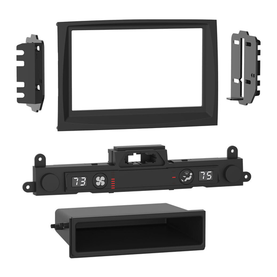
KIT COMPONENTS
• A) Radio trim panel • B) Radio brackets • C) Pocket • D) Climate display • E) (2) #8 x 3/8" Phillips screws • F) Wiring harness (not shown)
A
B
Metra. The World's Best Kits.
®
Kia Sportage
*Visit
MetraOnline.com
for more detailed information about the product and up-to-date vehicle
specific applications
† Display radio is an Android Auto/Apple CarPlay radio
KIT FEATURES
• ISO DIN radio provision with pocket
• ISO DDIN radio provision
• Includes an ASWC-1, AX-CAM6V, antenna adapter, and wiring
harness for a complete installation
C
MetraOnline.com
2017-2019
(without NAV, with Display radio†)
D
E
© COPYRIGHT 2019 METRA ELECTRONICS CORPORATION
99-7389B
I N S TA L L AT I O N I N S T R U C T I O N S
TABLE OF CONTENTS
Dash Disassembly ...............................................2-3
Kit Preparation ...................................................4-6
Kit Assembly ..........................................................7
Wiring Instructions ........................................... 8-15
WIRING & ANTENNA CONNECTIONS
Wiring Harness: Included with kit
Antenna Adapter: Included with kit
TOOLS REQUIRED
• Panel removal tool • Phillips screwdriver
• Pick tool
Attention!
Let the vehicle sit with the key
out of the ignition for a few minutes before
removing the factory radio. When testing the
aftermarket equipment, ensure that all factory
equipment is connected before cycling the
key to ignition.
REV. 12/4/19 INST99-7389B
Advertisement

Related Manuals for Metra Electronics 99-7389B


Summary of Contents for Metra Electronics 99-7389B
- Page 1 When testing the aftermarket equipment, ensure that all factory equipment is connected before cycling the key to ignition. Metra. The World’s Best Kits. MetraOnline.com ® © COPYRIGHT 2019 METRA ELECTRONICS CORPORATION REV. 12/4/19 INST99-7389B...
- Page 2 DASH DISASSEMBLY 1. Unclip and slide the top of the center 3. Unclip the panel above the glove box. console back slightly. (Figure A) Unplug the passenger airbag light, then remove the panel. (Figure C) 2. Unclip and remove the panel on the 4.
- Page 3 DASH DISASSEMBLY (CONT.) 5. Remove (4) Phillips screws securing the 7. Remove (1) Phillips screw securing the radio. Slide the radio out, then unplug lower right side drivers knee bolster. and remove the radio. (Figure E) Unsnap the bolster just enough to access the (1) Phillips screw securing the 6.
- Page 4 From the factory radio trim panel: 1. Remove (4) Phillips screws securing the inner trim panel, then remove the panel. (Figure A) To the factory radio trim panel: 2. Secure the 99-7389B radio trim panel to the panel using with the factory screws. (Figure B) Continued on the next page (Figure A) (Figure B) 1.800.221.0932...
- Page 5 KIT PREPARATION (CONT.) Climate Display Installation 1. Remove (4) Phillips screws securing the radio/hazard assembly to the climate/ radio control panel, then unclip and remove the assembly. (Figure C, heavier arrows) 2. Remove (9) Phillips screws securing the back cover to the radio/hazard assembly, then remove the cover.
- Page 6 KIT PREPARATION (CONT.) 4. Clip the hazard switch into the climate display. (Figure E) 5. Secure the climate-display/hazard- switch assembly to the climate control panel using the factory screws. (Figure F Continue to Kit Assembly (Figure F) (Figure E) 1.800.221.0932 MetraOnline.com...
- Page 7 KIT ASSEMBLY ISO DIN radio provision with pocket ISO DDIN radio provision 1. Secure the radio brackets to the pocket 1. Secure the radio brackets to the radio using the (2) #8 x 3/8” Phillips screws using the screws supplied with the provided. (Figure A) radio.
-
Page 8: Table Of Contents
WIRING INSTRUCTIONS FEATURES TABLE OF CONTENTS • Retains audio controls on the steering wheel via an ASWC-1 Connections ..........................9-10 • Provides NAV outputs (speed sense) Installation ...........................10 • Retains the factory AUX-IN jack Final Assembly ..........................11 • Retains the factory backup camera Programming the ASWC-1 and climate display ................11 •... -
Page 9: Connections
CONNECTIONS The following (1) wire is only for a multimedia/navigation radio that requires this wire. From the wiring harness included with the kit to the aftermarket radio: • Connect the Blue/Pink wire to the VSS/speed sense wire. • Connect the (2) Black wires, the Black wire labeled “CAMERA GROUND”, and also the Black wire from the AX-CAM6V, to the ground wire. •... -
Page 10: Installation
INSTALLATION CONNECTIONS (CONT.) With the key in the off position: 3.5mm jack steering wheel control retention: 1. Connect the wiring harness included with the kit to the climate-display/hazard-switch The 3.5mm jack is to be used to retain audio controls on the steering wheel. assembly, and then to the wiring harness in the vehicle. -
Page 11: Final Assembly
PROGRAMMING THE ASWC-1 AND CLIMATE DISPLAY Programming the ASWC-1: Programming the climate display: 1. Press and hold the “Volume-Up” button on the steering wheel, then turn the ignition on. 7. Turn the parking lights on. The L.E.D. will start flashing rapidly, which means the ASWC-1 is looking for the vehicle 8. -
Page 12: Aswc-1 Steering Wheel Control Settings
ASWC-1 STEERING WHEEL CONTROL SETTINGS L.E.D. feedback * Note: If the Axxess interface flashes Red (7) times, and you do not have an Alpine radio connected to it, that means the Axxess interface does not detect a radio connected to it. Verify The (18) Red L.E.D. -
Page 13: Changing Radio Type
ASWC-1 STEERING WHEEL CONTROL SETTINGS (CONT.) Changing radio type Radio Legend If the L.E.D. flashes do not match the radio you have connected, you must manually program the Radio Number Radio Radio Number Radio Axxess interface to tell it what radio it is connected to. Eclipse (type 1) Clarion (type 2) 1. -
Page 14: Remapping The Steering Wheel Control Buttons
ASWC-1 STEERING WHEEL CONTROL SETTINGS (CONT.) Remapping the steering wheel control buttons Button Function Legend Once the ASWC-1 has been programmed, the button assignment for the steering wheel controls Function # Function Function # Function may be reassigned if so desired. For example, if the “Seek-Up” button is preferred to be the Volume-Up Band “Mute”... -
Page 15: Dual Assignment Instructions (Long Button Press)
ASWC-1 STEERING WHEEL CONTROL SETTINGS (CONT.) Dual assignment instructions (long button press) Dual Assignment Legend The ASWC-1 has the capability to assign (2) functions to a single button, except “Volume-Up” and Function # Function Function # Function “Volume-Down”. Follow the steps below to program the button(s) to the desired setting. Not allowed Band Note: “Seek-Up”... - Page 16 Log onto www.installerinstitute.com or call 800-354-6782 for more information and take steps toward a better tomorrow. Metra recommends MECP certified technicians Metra. The World’s Best Kits. MetraOnline.com ® © COPYRIGHT 2019 METRA ELECTRONICS CORPORATION REV. 12/4/19 INST99-7389B...
- Page 17 • Wiring harness (not shown) WIRING & ANTENNA CONNECTIONS • Wiring Harness: Included with kit HARDWARE INCLUDED • Antenna Adapter: Included with kit SALES 386-257-2956 Metra. The World’s best kits. MetraOnline.com ® © COPYRIGHT 2019 METRA ELECTRONICS CORPORATION REV. 12/4/19...