Siemens SIMATIC ET 200SP Equipment Manual
Cm ptp communications module
Hide thumbs
Also See for SIMATIC ET 200SP:
- System manual (320 pages) ,
- Manual (270 pages) ,
- Operating instructions manual (166 pages)
Table of Contents
Advertisement
Advertisement
Table of Contents

Related Manuals for Siemens SIMATIC ET 200SP


Summary of Contents for Siemens SIMATIC ET 200SP
- Page 1 Preface Documentation guide SIMATIC Product overview Connecting ET 200SP CM PtP communications module (6ES7137-6AA01-0BA0) Parameters/address space Programming Equipment Manual Interrupts/diagnostics alarms Technical specifications 03/2021 A5E03790792-01...
- Page 2 Note the following: WARNING Siemens products may only be used for the applications described in the catalog and in the relevant technical documentation. If products and components from other manufacturers are used, these must be recommended or approved by Siemens. Proper transport, storage, installation, assembly, commissioning, operation and maintenance are required to ensure that the products operate safely and without any problems.
-
Page 3: Preface
This documentation provides important information on installing, wiring and commissioning the ET 200SP point-to-point communications module. This device manual complements the system manual ET 200SP distributed I/O system (http://support.automation.siemens.com/WW/view/en/58649293). General functions of the ET 200SP are described in the system manual ET 200SP distributed I/O system (http://support.automation.siemens.com/WW/view/en/58649293). - Page 4 This information is provided by the Siemens Industry Online Support in the Internet (https://support.industry.siemens.com). Industry Mall The Industry Mall is the catalog and order system of Siemens AG for automation and drive solutions on the basis of Totally Integrated Automation (TIA) and Totally Integrated Power (TIP).
- Page 5 Siemens accepts no liability for the use of the open source software over and above the intended program sequence, or for any faults caused by modifications to the software.
-
Page 6: Table Of Contents
Table of contents Preface ..............................3 Documentation guide ..........................7 Product overview ..........................11 Properties .......................... 11 Functions .......................... 15 Properties of the interfaces ....................16 2.3.1 Properties of the RS232 interface ..................16 2.3.2 Properties of the RS422/485 interface ................18 Connecting ............................ -
Page 7: Documentation Guide
This arrangement enables you to access the specific content you require. Basic information The System Manual and Getting Started describe in detail the configuration, installation, wiring and commissioning of the SIMATIC ET 200SP distributed I/O system. The STEP 7 online help supports you in the configuration and programming. Device information Product manuals contain a compact description of the module-specific information, such as properties, wiring diagrams, characteristics and technical specifications. - Page 8 You can download the product information free of charge from the Internet (https://support.industry.siemens.com/cs/us/en/view/73021864). Manual Collection ET 200SP The Manual Collection contains the complete documentation on the SIMATIC ET 200SP distributed I/O system gathered together in one file. You can find the Manual Collection on the Internet (https://support.industry.siemens.com/cs/ww/en/view/84133942).
- Page 9 • Manuals, characteristics, operating manuals, certificates • Product master data You can find "mySupport" - CAx data on the Internet (http://support.industry.siemens.com/my/ww/en/CAxOnline). Application examples The application examples support you with various tools and examples for solving your automation tasks. Solutions are shown in interplay with multiple components in the system - separated from the focus on individual products.
- Page 10 You can find the SIMATIC Automation Tool on the Internet (https://support.industry.siemens.com/cs/ww/en/view/98161300). PRONETA SIEMENS PRONETA (PROFINET network analysis) allows you to analyze the plant network during commissioning. PRONETA features two core functions: • The topology overview automatically scans the PROFINET and all connected components.
-
Page 11: Product Overview
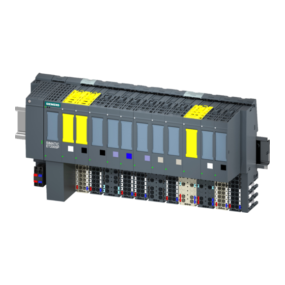
Product overview Properties Article number 6ES7137-6AA01-0BA0 (packing unit: pack of 1) 6ES7137-6AA01-2BA0 (packing unit: pack of 10) The CM PtP communications module with article number 6ES7137-6AA01-0BA0 and firmware version V2.0 replaces the CM PtP with article number 6ES7137-6AA00-0BA0. Firmware version This manual describes the properties of firmware version V2.0 of the module. - Page 12 Product overview 2.1 Properties View of the module ① Module type and designa- ⑦ Function class tion ② LED for diagnostics ⑧ Module type color coding ③ 2D matrix code ⑨ Function and firmware version ④ Terminal diagram ⑩ Color code for selection of the color-coded labels and BaseUnit type ⑤...
- Page 13 BaseUnits you can use with the communications module in Product information on the documentation of the ET 200SP distributed I/O system (http://support.automation.siemens.com/WW/view/en/73021864). You can find additional information on the accessories in the ET 200SP distributed I/O system (http://support.automation.siemens.com/WW/view/en/58649293) system manual. CM PtP communications module (6ES7137-6AA01-0BA0) Equipment Manual, 03/2021, A5E03790792-01...
- Page 14 ET 200SP distributed I/O system (http://support.automation.siemens.com/WW/view/en/58649293). Additional information on using the CM PtP without the prepared instruction libraries is available in the programming and operating manual CM PtP operation with PROFINET controller (http://support.automation.siemens.com/WW/view/en/59062563). CM PtP communications module (6ES7137-6AA01-0BA0) Equipment Manual, 03/2021, A5E03790792-01...
-
Page 15: Functions
Information on configuration and programming of the CM PtP communications module is available in the function manual CM PtP - Configurations for point-to-point connections (http://support.automation.siemens.com/WW/view/en/59057093) and in the information system of STEP 7 (TIA Portal). CM PtP communications module (6ES7137-6AA01-0BA0) -
Page 16: Properties Of The Interfaces
Product overview 2.3 Properties of the interfaces Properties of the interfaces Interfaces of the CM PtP The CM PtP has the following interfaces, which are connected (Page 19) by means of the associated BaseUnit: • RS232 interface • RS422/485 interface 2.3.1 Properties of the RS232 interface Definition... - Page 17 Product overview 2.3 Properties of the interfaces RS232 signals The table below shows the meaning of the individual RS232 accompanying signals. Table 2- 2 Signals of the RS232 interface Signal Designation Meaning Transmit Data Transmit data; transmit cable logically held to "1" by communications module in idle state.
-
Page 18: Properties Of The Rs422/485 Interface
Product overview 2.3 Properties of the interfaces 2.3.2 Properties of the RS422/485 interface Definition The RS422/485 (X27) interface is a differential voltage interface for serial data transmission. Properties The RS422/485 (X27) interface has the following properties and meets the following requirements: Type Differential voltage interface... -
Page 19: Connecting
Product information on the documentation of the ET 200SP distributed I/O system (http://support.automation.siemens.com/WW/view/en/73021864). You can find information about selecting a suitable BaseUnit in the ET 200SP Distributed I/O system (http://support.automation.siemens.com/WW/view/en/58649293) system manual and ET 200SP BaseUnits (http://support.automation.siemens.com/WW/view/en/58532597/133300) manual. You can find information on wiring the BaseUnit, connecting cable shields, etc. in the Wiring section of the ET 200SP Distributed I/O system (http://support.automation.siemens.com/WW/view/en/73021864) system manual. -
Page 20: Rs232 Interface Of The Communications Module
Connecting 3.2 RS232 interface of the communications module RS232 interface of the communications module RS232 interface The RS232 interface is a voltage interface used for serial data transmission. The inputs and outputs are not isolated from each other. The inputs and outputs are electrically isolated from the backplane bus. - Page 21 Connecting 3.2 RS232 interface of the communications module Block diagram You must ground the shields of the cables between communication partner and communications module both through the shield contact on the BaseUnit (shield bracket and terminal) and on the communication partner. The figure below shows the block diagram of the communications module for operation at the RS232 connection.
- Page 22 Connecting 3.2 RS232 interface of the communications module Additional information Information on connecting the modules can be found in the ET 200SP distributed I/O system (http://support.automation.siemens.com/WW/view/en/58649293) system manual. CM PtP communications module (6ES7137-6AA01-0BA0) Equipment Manual, 03/2021, A5E03790792-01...
-
Page 23: Rs422/485 Interface Of The Communications Module
Connecting 3.3 RS422/485 interface of the communications module RS422/485 interface of the communications module RS422/485 interface The RS422/485 (X27) interface is a differential voltage interface for serial data transmission. The inputs and outputs are not isolated from each other. The inputs and outputs are electrically isolated from the backplane bus. - Page 24 Connecting 3.3 RS422/485 interface of the communications module Block diagram You must ground the shields of the cables between communication partner and communications module both through the shield contact on the BaseUnit (shield bracket and terminal) and on the communication partner. The figure below shows the block diagram of the communications module for operation at the RS422/485 connection.
-
Page 25: Installation Guidelines
330 Ω at the receiver end. Additional information Information on connecting the modules can be found in the FAQ with the entry ID 109736665 (https://support.industry.siemens.com/cs/ww/en/view/109736665) and in the ET 200SP distributed I/O system (http://support.automation.siemens.com/WW/view/en/58649293) system manual. Installation guidelines... -
Page 26: Parameters/Address Space
CM PtP Device configuration and pa- tion and MODBUS (RTU) with rameter setting with GSD file the entry ID 75226762 (https://support.industry.sieme ns.com/cs/ww/en/view/75226 762) in the Siemens Industry Online Support Distributed operation Third-party configuration Instructions for control and • Third-party automation system... -
Page 27: Reaction To Cpu Stop
GSD file The respective GSD file for the ET 200SP distributed I/O system is available for download on the Internet: • GSD file PROFINET IO (http://support.automation.siemens.com/WW/view/en/57138621) • GSD file PROFIBUS DP (http://support.automation.siemens.com/WW/view/en/73016883) Reaction to CPU STOP Ongoing transmissions are aborted when the higher-level control (CPU) goes to STOP. -
Page 28: Parameter Setting
Parameters/address space 4.3 Parameter setting Parameter setting You can use various parameters to define the properties of the communications module. Depending on the settings, not all parameters are available. You set the parameters of the module as follows: Parameter setting via ... Basic procedure Hardware configuration in STEP 7 1. - Page 29 Parameters/address space 4.3 Parameter setting Parameters of CM PtP The following parameter settings are possible. The default settings of the parameters are shown in bold in the "Value range" column. Table 4- 1 Programmable parameters Parameter Value range Scope Potential group Module •...
- Page 30 Parameters/address space 4.3 Parameter setting Parameter Value range Scope Parity Channel None • • Even • • Mark: Set parity bit to 1 • Space: Set parity bit to 0 • Data bits Channel 8 bits • • 7 bits Stop bits Channel •...
- Page 31 Parameters/address space 4.3 Parameter setting Parameter Value range Scope No. of end delimiters 0...1...2 Channel 1st end delimiter (Hex) 0...FF Channel 0...FF 2nd end delimiter (Hex) Channel 0...5 Number of appended char- Channel acters Channel Frame Start on any character •...
- Page 32 Parameters/address space 4.3 Parameter setting Parameter Value range Scope Read message length from Channel Deactivated • message • Activated Offset of length field in 0...2047 bytes Channel message Size of length field Channel • 1 byte • 2 bytes • 4 bytes Number of characters not 0...255 bytes...
- Page 33 The device manual of the communications module is supplemented by the function manual CM PtP - Configurations for point-to-point connections (http://support.automation.siemens.com/WW/view/en/59057093) and the STEP 7 (TIA Portal) information system. There you will find information on the following topics: • Operating modes •...
-
Page 34: Address Space
Parameters/address space 4.4 Address space Address space Address space of the communications module The size of the input and output addresses of the communications module depends on whether the performance optimization option (Page 35) is enabled. Table 4- 2 Size of the input and output addresses Inputs Outputs Size without performance opti-... -
Page 35: Programming
Programming Programming Data communication Two types of data exchange between the CPU and the communications module are possible: • Acyclic data exchange (Universal) The point-to-point instructions communicate with the communications module asynchronously by reading or writing data records. Data transmission takes place across several cycles. Note CPU configuration limits When using the instructions with asynchronous communication, you should take into... - Page 36 Additional information Additional information on programming the communications modules is available in the function manual CM PtP - Configurations for point-to-point connections (http://support.automation.siemens.com/WW/view/en/59057093) and in the STEP 7 (TIA Portal) information system. CM PtP communications module (6ES7137-6AA01-0BA0) Equipment Manual, 03/2021, A5E03790792-01...
-
Page 37: Interrupts/Diagnostics Alarms
Interrupts/diagnostics alarms Status and error displays LEDs The figure below shows the LEDs (status and error displays) of the CM PtP. ① DIAG (green/red) ② TX (green) ③ RX (green) ④ PWR (green) Figure 6-1 LED displays CM PtP (without BaseUnit) CM PtP communications module (6ES7137-6AA01-0BA0) Equipment Manual, 03/2021, A5E03790792-01... - Page 38 Evaluate the diagnostics alarms and eliminate the (at least one error pending) error. Flashes Information on communications module startup and diagnostics is available in the CM PtP - Configurations for point-to-point connections (http://support.automation.siemens.com/WW/view/en/59057093) function manual Table 6- 2 Status displays TXD/RXD Meaning Solution Interface is transmitting...
-
Page 39: Diagnostic Alarms
"RALRM" (Read additional alarm information), in the information system of STEP 7 and in function manual Diagnostics (https://support.industry.siemens.com/cs/ww/en/view/59192926), section "System diagnostics in user program". If the module is being operated as a distributed module in an ET 200SP system with PROFIBUS DP, you have the option of reading out diagnostic data with the RDREC or RD_REC instruction using data record 0 and 1. - Page 40 Interrupts/diagnostics alarms 6.2 Diagnostic alarms Diagnostic messages The diagnostics are displayed as plain text in STEP 7 (TIA Portal) in the online and diagnostics view. You can evaluate the error codes with the user program. The following diagnostics can be signaled: Table 6- 5 Diagnostic messages, their meaning and remedies Diagnostic mes-...
-
Page 41: Technical Specifications
Technical specifications Article number 6ES7137-6AA01-0BA0 General information Product type designation CM PtP Firmware version • FW update possible usable BaseUnits BU type A0 Product function Yes; I&M0 to I&M3 • I&M data Engineering with • STEP 7 TIA Portal configurable/integrated STEP 7 V17 or higher from version via GSD as of V5.6 HF4... - Page 42 Technical specifications Article number 6ES7137-6AA01-0BA0 Interface types RS 232 115.2 kbit/s • Transmission rate, max. 15 m • Cable length, max. RTS, CTS, DTR, DSR, RI, DCD • RS 232 auxiliary signals RS 485 250 kbit/s • Transmission rate, max. 1 200 m;...
- Page 43 Technical specifications Article number 6ES7137-6AA01-0BA0 Interrupts/diagnostics/status information Diagnostics function Alarms • Diagnostic alarm • Hardware interrupt Diagnoses • Wire-break Diagnostics indication LED Monitoring of the supply voltage (PWR-LED) Yes; green PWR LED • Yes; green/red DIAG LED • for module diagnostics Yes;...
- Page 44 2000 m above sea level in the "Mechanical and climatic environmental conditions" section of the ET 200SP Distributed I/O system (http://support.automation.siemens.com/WW/view/en/58649293) system manual. Additional general technical specifications for SIMATIC ET 200SP can be found in the ET 200SP distributed I/O system (http://support.automation.siemens.com/WW/view/en/58649293) system manual.