Table of Contents
Advertisement
Quick Links
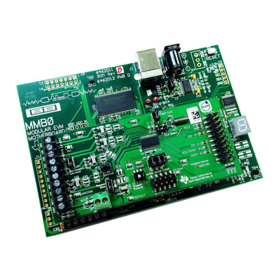
This user's guide describes the operation and use of the ADS126x evaluation module (ADS126xEVM).
The
ADS1262
and
for precision industrial applications. The performance demonstration kit (PDK) is intended for prototyping
and evaluating the ADS1262 and ADS1263. The
card, MMB0 motherboard, A-to-B USB cable, 6-V wall-adapter power supply, and supporting software.
This document includes a detailed description of the hardware and software, bill of materials, and
schematic for the ADS126xEVM.
Throughout this document, the terms ADS126xEVM, demonstration kit, evaluation board, evaluation
module, and EVM are synonymous with the ADS126xEVM-PDK.
The following EVM-compatible devices and related documents are available through the Texas
Instruments website at www.ti.com.
E2E is a trademark of Texas Instruments, Inc.
Windows XP, Windows 7 are trademarks of Microsoft Corporation.
X2Y is a registered trademark of X2Y Attenuators, LLC.
All other trademarks are the property of their respective owners.
SBAU206 – April 2015
Submit Documentation Feedback
ADS126xEVM-PDK
ADS1263
are low-noise, low-drift 32-bit delta-sigma analog-to-digital converters (ADC)
Related Documents
Device
ADS1262
ADS1263
TPS79225
TPS72325
Copyright © 2015, Texas Instruments Incorporated
ADS126xEVM-PDK
ADS126xEVM-PDK
includes the ADS126xEVM daughter
Literature Number
SBAS661
SLVS337B
SLVS346C
User's Guide
SBAU206 – April 2015
1
ADS126xEVM-PDK
Advertisement
Table of Contents

Related Manuals for Texas Instruments ADS126 EVM-PDK Series


Summary of Contents for Texas Instruments ADS126 EVM-PDK Series
- Page 1 TPS79225 SLVS337B TPS72325 SLVS346C E2E is a trademark of Texas Instruments, Inc. Windows XP, Windows 7 are trademarks of Microsoft Corporation. X2Y is a registered trademark of X2Y Attenuators, LLC. All other trademarks are the property of their respective owners.
-
Page 2: Table Of Contents
Tab 9: Register Map ..................... Tab 10: Extras / About ...................... Data Monitor Window ....................Status Byte Error Pop-up List of Tables ....................Factory Default Settings ADS126xEVM-PDK SBAU206 – April 2015 Submit Documentation Feedback Copyright © 2015, Texas Instruments Incorporated... - Page 3 ......................Critical Connections ....................J1, Serial Interface Header ................... ADS126x Analog Input Pin Functions ..................ADS126xEVM Bill of Materials SBAU206 – April 2015 ADS126xEVM-PDK Submit Documentation Feedback Copyright © 2015, Texas Instruments Incorporated...
-
Page 4: Ads126Xevm Overview
The MMB0 is intended to be used with the accompanying EVM software and does not have additional resources to support the use as a firmware development platform. ADS126xEVM-PDK SBAU206 – April 2015 Submit Documentation Feedback Copyright © 2015, Texas Instruments Incorporated... -
Page 5: Ads126Xevm Hardware
The JP2, JP3, and JP5 jumpers are not required. Theses jumpers modify the analog input connections for biasing and ratiometric measurements. See Section 2.6 for more details. SBAU206 – April 2015 ADS126xEVM-PDK Submit Documentation Feedback Copyright © 2015, Texas Instruments Incorporated... -
Page 6: Quick Reference
Analog or reference inputs Channels 6-7 J3.7-8 AIN6-AIN7 Analog inputs Analog inputs Channels 8-9 J4.2,1 AIN8, AIN9 Thermocouple or analog inputs Analog or common-reference Channel 10 J3.10 AINCOM input ADS126xEVM-PDK SBAU206 – April 2015 Submit Documentation Feedback Copyright © 2015, Texas Instruments Incorporated... -
Page 7: Power Supply
ADS126xEVM supplies. Figure 5 shows the JP4 jumpers, switch S2, and the power-supply test points. Figure 5. Power-Supply Circuitry (Default Jumper Settings) SBAU206 – April 2015 ADS126xEVM-PDK Submit Documentation Feedback Copyright © 2015, Texas Instruments Incorporated... -
Page 8: Mmb0 Configuration For The 6-V Wall Adapter
NOTE: TI recommends using an external power supply that complies with applicable regional safety standards such as (by example) UL, CSA, VDE, CCC, PSE, and so forth. ADS126xEVM-PDK SBAU206 – April 2015 Submit Documentation Feedback Copyright © 2015, Texas Instruments Incorporated... -
Page 9: Mmb0 Configuration For A Unipolar Bench Power Supply
ADS126xEVM. Open jumper (J12) USB connector ± Shorted jumper (J13B) Power Input Figure 7. MMB0 Configuration for a Unipolar Bench Power Supply SBAU206 – April 2015 ADS126xEVM-PDK Submit Documentation Feedback Copyright © 2015, Texas Instruments Incorporated... -
Page 10: Mmb0 Configuration For A Bipolar Bench Power Supply
MMB0 jumper J13A has no effect on the circuit behavior of the ADS126xEVM as long as no other supply is connected to +VA. Do not short jumper J13A when another supply is connected to +VA. ADS126xEVM-PDK SBAU206 – April 2015 Submit Documentation Feedback Copyright © 2015, Texas Instruments Incorporated... -
Page 11: Adc Clock Source Options
The external clock source must have a frequency between 1 MHz and 8 MHz, and have a peak-to-peak amplitude equal to the DVDD supply voltage. SBAU206 – April 2015 ADS126xEVM-PDK Submit Documentation Feedback Copyright © 2015, Texas Instruments Incorporated... -
Page 12: Digital Interface, J1
When probing SPI communications, check the signal integrity near the receiving end (that is, probe DIN at the ADS126x input, not at the SPI controller output). ADS126xEVM-PDK SBAU206 – April 2015 Submit Documentation Feedback Copyright © 2015, Texas Instruments Incorporated... -
Page 13: Analog Inputs
CM f-3dB = 319 kHz Top Side DM f-3dB = 1.59 kHz Cold Junction = GND Sensor Bias AINCOM Jumper Figure 10. Analog Input Support Circuitry on the ADS126xEVM SBAU206 – April 2015 ADS126xEVM-PDK Submit Documentation Feedback Copyright © 2015, Texas Instruments Incorporated... -
Page 14: Ads126X Analog Input Pin Functions
GPIO voltages are referenced to the analog power supply (AVDD and AVSS); therefore, the GPIOs must use 5-V logic. The GPIOs are useful for control of external devices, as well as reading external logic signals. ADS126xEVM-PDK SBAU206 – April 2015 Submit Documentation Feedback Copyright © 2015, Texas Instruments Incorporated... -
Page 15: Ads126Xevm Ratiometric Connection Example
RTD, use JP1 to replace the IN4 connection. For a 4-wire RTD, remove the IN6 to IN3 jumper wire, remove the IN7 to COM jumper wire, and connect the additional RTD wire to COM. SBAU206 – April 2015 ADS126xEVM-PDK Submit Documentation Feedback Copyright © 2015, Texas Instruments Incorporated... -
Page 16: J4 Thermocouple Input
(C1, C3, and C4 for example) required for common-mode and differential filtering. In addition to the board space saved by using X2Y, these capacitors have lower ESL and excellent common-mode capacitor matching. ADS126xEVM-PDK SBAU206 – April 2015 Submit Documentation Feedback Copyright © 2015, Texas Instruments Incorporated... -
Page 17: Ads126Xevm Software
6. After powering up the MMB0 and ADS126xEVM, power up any other external circuitry. 7. Run ADCPro and follow the steps in Section 3.3 to communicate with the ADS126xEVM. SBAU206 – April 2015 ADS126xEVM-PDK Submit Documentation Feedback Copyright © 2015, Texas Instruments Incorporated... -
Page 18: Using Adcpro With The Ads126Xevm
MMB0, refer back to Section 3.1 Section 3.2 for the required drivers and hardware connections. Figure 14. EVM Connection Status ADS126xEVM-PDK SBAU206 – April 2015 Submit Documentation Feedback Copyright © 2015, Texas Instruments Incorporated... -
Page 19: Ads1262Evm Plugin Tabs
Clicking Continuous captures blocks of data repeatedly. The block size is configured in the test plugin. 6. Use the test plugin functions as described in the ADCPro User's Guide, SBAU128, to analyze the ADC conversion data. SBAU206 – April 2015 ADS126xEVM-PDK Submit Documentation Feedback Copyright © 2015, Texas Instruments Incorporated... -
Page 20: Using The Ads126Xevm Plugin
ADC inputs. Remember to set a proper common-mode input voltage by applying an external midsupply voltage or by using the VBIAS function on AINCOM, as shown in Figure 1 Input MUX Figure 17. Tab 1 Settings ADS126xEVM-PDK SBAU206 – April 2015 Submit Documentation Feedback Copyright © 2015, Texas Instruments Incorporated... -
Page 21: Tab 2 Settings
The internal reference can be disabled when an external referenced is used; however, the internal reference must be enabled to use the IDACs. The ADC2 Reference Settings are only visible when an ADS1263EVM is connected. SBAU206 – April 2015 ADS126xEVM-PDK Submit Documentation Feedback Copyright © 2015, Texas Instruments Incorporated... -
Page 22: Tab 3 Settings
The fCLK frequency affects the calculated ADC1 Data Rate and ADC2 Data Rate indicators that are also used by the software when acquiring data, plotting the filter response, or calculating the FFT in the MultiFFT test plugin. ADS126xEVM-PDK SBAU206 – April 2015 Submit Documentation Feedback Copyright © 2015, Texas Instruments Incorporated... -
Page 23: Tab 4 Settings
Input Chop and AINCOM are duplicated on tab 1 (Input MUX) for quick access. NOTE: The software does not allow for simultaneous GPIO, Test DAC, IDAC, or VBIAS functions to be enabled on the same pin. SBAU206 – April 2015 ADS126xEVM-PDK Submit Documentation Feedback Copyright © 2015, Texas Instruments Incorporated... -
Page 24: Tab 5 Settings
GPIO output configuration from memory. NOTE: The software does not allow for simultaneous GPIO, Test DAC, IDAC, or VBIAS functions to be enabled on the same pin. ADS126xEVM-PDK SBAU206 – April 2015 Submit Documentation Feedback Copyright © 2015, Texas Instruments Incorporated... -
Page 25: Tab 6 Settings
ADC conversion result. NOTE: The software does not allow for simultaneous GPIO, Test DAC, IDAC, or VBIAS functions to be enabled on the same pin. SBAU206 – April 2015 ADS126xEVM-PDK Submit Documentation Feedback Copyright © 2015, Texas Instruments Incorporated... -
Page 26: Tab 7 Settings
ADC1 data are ready when the DRDY signal goes low, but there is no DRDY signal to indicate that new ADC2 is ready. As a result of this behavior, ADC2 data are lost if this requirement is not satisfied. ADS126xEVM-PDK SBAU206 – April 2015 Submit Documentation Feedback Copyright © 2015, Texas Instruments Incorporated... -
Page 27: Tab 8: Register Map
Offset can be changed from uV to mV as needed. Calibration is not required; however, calibration improves overall ADC accuracy by about an order of magnitude. SBAU206 – April 2015 ADS126xEVM-PDK Submit Documentation Feedback Copyright © 2015, Texas Instruments Incorporated... -
Page 28: Tab 9: Register Map
File button. Use this register map text file to document a particular setup. Reference this text file during development or support on the E2E™ Precision Data Converter Forum. ADS126xEVM-PDK SBAU206 – April 2015 Submit Documentation Feedback Copyright © 2015, Texas Instruments Incorporated... -
Page 29: Tab 10: Extras / About
MMB0 memory, then transferred to ADCPro using USB, and finally processed in ADCPro before it is displayed. SBAU206 – April 2015 ADS126xEVM-PDK Submit Documentation Feedback Copyright © 2015, Texas Instruments Incorporated... -
Page 30: Data Monitor Window
Switching to the View Data window is useful to see when this error first appeared in the collected data. Figure 28. Status Byte Error Pop-up ADS126xEVM-PDK SBAU206 – April 2015 Submit Documentation Feedback Copyright © 2015, Texas Instruments Incorporated... -
Page 31: Ads126Xevm Schematic And Bill Of Materials
100 kOhms R3-5 RES, 100k Ohm, 5%, 1/10W, 0603 Panasonic ERJ-3GEYJ104V 3.9 kOhms RES, 3.9K Ohm, 1/10W, 0.05%, 0603 Susumu RG1608N-392-W-T1 This component is not installed. SBAU206 – April 2015 ADS126xEVM-PDK Submit Documentation Feedback Copyright © 2015, Texas Instruments Incorporated... - Page 32 IC, EEPROM, 256 kBIT, 400 kHz, 8TSSOP Microchip 24AA256-I/ST Technology CRYSTAL, 7.3728 MHz, 18 pF, T/H ECS Inc. ECS-73-18-10X Installed for the ADS1262EVM. The ADS1263IPW is installed for the ADS1263EVM. ADS126xEVM-PDK SBAU206 – April 2015 Submit Documentation Feedback Copyright © 2015, Texas Instruments Incorporated...
- Page 33 -5VA Designed for:Public Release Mod. Date: 12/31/2014 DGND Texas Instruments and/or its licensors do not warrant the accuracy or completeness of this Sensor Bias Project: ADS126xEVM AINCOM AGND specification or any information contained therein. Texas Instruments and/or its licensors do not...
- Page 34 STANDARD TERMS AND CONDITIONS FOR EVALUATION MODULES Delivery: TI delivers TI evaluation boards, kits, or modules, including any accompanying demonstration software, components, or documentation (collectively, an “EVM” or “EVMs”) to the User (“User”) in accordance with the terms and conditions set forth herein. Acceptance of the EVM is expressly subject to the following terms and conditions.
- Page 35 FCC Interference Statement for Class B EVM devices NOTE: This equipment has been tested and found to comply with the limits for a Class B digital device, pursuant to part 15 of the FCC Rules. These limits are designed to provide reasonable protection against harmful interference in a residential installation.
- Page 36 【無線電波を送信する製品の開発キットをお使いになる際の注意事項】 開発キットの中には技術基準適合証明を受けて いないものがあります。 技術適合証明を受けていないもののご使用に際しては、電波法遵守のため、以下のいずれかの 措置を取っていただく必要がありますのでご注意ください。 1. 電波法施行規則第6条第1項第1号に基づく平成18年3月28日総務省告示第173号で定められた電波暗室等の試験設備でご使用 いただく。 2. 実験局の免許を取得後ご使用いただく。 3. 技術基準適合証明を取得後ご使用いただく。 なお、本製品は、上記の「ご使用にあたっての注意」を譲渡先、移転先に通知しない限り、譲渡、移転できないものとします。 上記を遵守頂けない場合は、電波法の罰則が適用される可能性があることをご留意ください。 日本テキサス・イ ンスツルメンツ株式会社 東京都新宿区西新宿6丁目24番1号 西新宿三井ビル 3.3.3 Notice for EVMs for Power Line Communication: Please see http://www.tij.co.jp/lsds/ti_ja/general/eStore/notice_02.page 電力線搬送波通信についての開発キットをお使いになる際の注意事項については、次のところをご覧くださ い。http://www.tij.co.jp/lsds/ti_ja/general/eStore/notice_02.page SPACER EVM Use Restrictions and Warnings: 4.1 EVMS ARE NOT FOR USE IN FUNCTIONAL SAFETY AND/OR SAFETY CRITICAL EVALUATIONS, INCLUDING BUT NOT LIMITED TO EVALUATIONS OF LIFE SUPPORT APPLICATIONS.
- Page 37 Notwithstanding the foregoing, any judgment may be enforced in any United States or foreign court, and TI may seek injunctive relief in any United States or foreign court. Mailing Address: Texas Instruments, Post Office Box 655303, Dallas, Texas 75265 Copyright © 2015, Texas Instruments Incorporated...
- Page 38 IMPORTANT NOTICE Texas Instruments Incorporated and its subsidiaries (TI) reserve the right to make corrections, enhancements, improvements and other changes to its semiconductor products and services per JESD46, latest issue, and to discontinue any product or service per JESD48, latest issue.