Table of Contents
Advertisement
Quick Links
Advertisement
Table of Contents

Related Manuals for UNI-T UTR2810E Series


Summary of Contents for UNI-T UTR2810E Series
- Page 1 UTR2810E Series LCR Meter User Manual www.uni-trend.com...
-
Page 2: Preface
If the products is shipped domestically to the purchase receipt of the original purchaser. If the product is shipped to the location of the UNI-T service center, UNI-T shall pay the return shipping fee. If the product is sent to any other location, the customer shall be responsible for all shipping, duties, taxes, and any other expenses. -
Page 3: Safety Instructions
UTR2810E Series LCR Meter – User Manual Safety Instructions Warning Danger: To avoid possible electric shock and personal safety problem, please follow the instructions below. Please read the following safety information carefully beforestarting to use the instrument. Disclaimer Uni-Trend will not be responsible for the personal safety and property damage caused by the user's failure to comply with the following terms. - Page 4 Do not dispose the product and its accessories in trash bin. If the following abnormal conditions occurs, please terminate the operation and disconnect the power cable immediately. Contact the sales department of UNI-T for repair immediately. Failure to do so will result in fire or potential electrocution hazard to operators.
-
Page 5: Table Of Contents
UTR2810E Series LCR Meter – User Manual Table of Contents Preface ....................................2 Copyright Information ................................ 2 Warranty Service ................................2 Guarantee Limit ................................2 Safety Instructions................................3 Table of Contents ................................5 Before Use ..................................7 1.1 Out of Box Audit ................................7 1.2 Requirements of Power Supply ........................... - Page 6 UTR2810E Series LCR Meter – User Manual 3.4.2 Nominal Value Setup............................20 3.4.3 Comparison Function ............................20 3.4.4 Comparison Mode ............................21 3.4.5【Upper Limit】,【Lower Limit】Parameter Setting ..................21 4. Instruction of Handler Interface ............................22 4.1 Brief Introduction ............................... 22 4.2 Operating Instruction ..............................
-
Page 7: Before Use
UTR2810E Series LCR Meter – User Manual Before Use Thank you for purchasing UNI-T product! Please read this chapter carefully before use. In this chapter you will learn the following: Out of box audit Requirements of power supply ... -
Page 8: Operating Environment
UTR2810E Series LCR Meter – User Manual 1.4 Operating Environment (1) Do not use the instrument in dust, shaking, direct sunlight and etchant gas environment. (2) Please use the instrument in operating temperature 0℃~40℃,relative humidity ≤75%,to ensure the accuracy of measurement (3)... -
Page 9: Introduction Of Panel
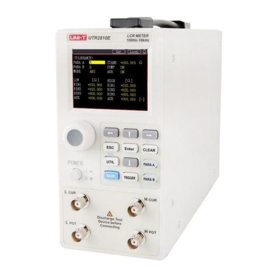
UTR2810E Series LCR Meter – User Manual Introduction of Panel In this chapter you will learn the following: Front Panel Rear Panel Display Area 2.1 Front Panel The front panel of UTR2810E, see the Figure 2-1. Figure 2-1 Front Panel Table 2-1 Function description of front panel 2.2 Back Panel... - Page 10 UTR2810E Series LCR Meter – User Manual Hcur:current excitation high-end Hpot:voltage pressure high-end Test lead Lpot:voltage pressure low-end Lcur:current excitation low-end Direction key Escape Enter Confirmed Rest key( This version does not support REC ) CLEAR Button The first function is UTIL...
-
Page 11: Display Area
UTR2810E Series LCR Meter – User Manual 2.3 Display Area The UTR2810E display area is divided into the following parts, see Figure 2-3 Figure 2-3 Display Area 2.3.1 MEAS DISP Dispaly Primary parameter Z/R/L/C/G /Y Secondary paramter X/Q/D /R/Θ(deg)/Θ(rad)/B 2.3.2 SET DISP (1) Paramter A Z:... - Page 12 UTR2810E Series LCR Meter – User Manual (4) Electrical level 0.1 V:The current measured signal voltage is 0.1 V. 0.3 V:The current measured signal voltage is 0.3 V. 1.0 V:The current measured signal voltage is 1.0 V. (5) Speed FAST: Fast speed test MED:...
-
Page 13: Operating Instruction
UTR2810E Series LCR Meter – User Manual Operating Instruction In this chapter you will learn the following: Boot up First function operating Second function operating 3.1 Boot up 1)Press【POWER】key to boot up the instrument. 2)Enter test state after delay, see Figure 3-1, the actual situation may different. -
Page 14: Frequency
UTR2810E Series LCR Meter – User Manual Θ(deg) Phase angle Parameter B Θ(rad) Phase angle(arc) (secondary Susceptance value parameter) Reactance value Resistance value The UTR2810E/2811E can simultaneously measure two different parameter combinations of the measured impedance in one test cycle. The primary and secondary parameters are as follows: Z is positive value,L/C/R has positive and negative value. -
Page 15: Range
UTR2810E Series LCR Meter – User Manual Speed Description FAST About 23.3 times per second About 5.4 times per second SLOW About 2.8 times per second 3.2.5 Range UTR2810E/2811E provides 12 range 3Ω,10Ω, 30Ω,100Ω,300Ω,1kΩ,3 kΩ,10kΩ,30k,100kΩ, 300kΩ and Auto. The effective measuring range of each range is shown below. -
Page 16: Clear
UTR2810E Series LCR Meter – User Manual Between the above impedance, use an appropriate equivalent circuit as recommended by the component manufacturer. (2)The choice of inductance equivalent circuit Large inductance corresponds to high impedance value, and the influence of parallel resistance is greater than series resistance. - Page 17 UTR2810E Series LCR Meter – User Manual completed. It can be escape or continue the short-circuit zero clearing test. Step 5 LCD displays information “keep fixture short”; If the instrument need to do short circuit zero clearing, connect the short-circuit plate to the test fixture, or connect the test wire black clip and red clip together;...
-
Page 18: Trigger Setup
UTR2810E Series LCR Meter – User Manual reliable. It should connect to short circuit and then perform the zero clearing again. 4) Zero clearing data will store in nonvolatile memory. Under the same test conditions, the instrument does not need to zero clear. -
Page 19: Qualified Beeper
UTR2810E Series LCR Meter – User Manual Baud Rate Description 1200 Tramsmit data 1200 bits per second 9600 Tramsmit data 9600 bits per second 38400 Tramsmit data 38400 bits per second 57600 Tramsmit data 57600 bits per second 115200 Tramsmit data 115200 bits per second 3.3.3 Qualified Beeper... -
Page 20: View System Information
UTR2810E Series LCR Meter – User Manual Save Setting Description Turn on auto save Turn off auto save 3.3.10 View System Information After view the system information, press【ENTER】or【ESC】to exit the system information interface. 3.4 Sorting Setup Deviation mode is used to control the display way of the result, deviation display is to show the difference between measured value and reference value. -
Page 21: Comparison Mode
UTR2810E Series LCR Meter – User Manual Comparison/Auxiliary Function Turn on comparsion function Turn off comparsion function 3.4.4 Comparison Mode UTR2810E/2811E provides 3 comparsion modes:SEQ,ABS and %(percentage deviation),the latter two are collectively referred to as tolerance mode(TOL). TOL:set the deviation of the nomial value to be the limit of comparsion;... -
Page 22: Instruction Of Handler Interface
UTR2810E Series LCR Meter – User Manual 4. Instruction of Handler Interface In this chapter you will learn the following: Brief Introduction Operating Instruction 4.1 Brief Introduction UTR2810E provides Handler interface,this interface is used for outputs sorting result of the instrument. -
Page 23: Connection Terminal And Signal
UTR2810E Series LCR Meter – User Manual Figure 4-1 Example of Turn on Comparison and Auxiliary Function at the same time Figure 4-2 Example of Turn on Comparison Function Figure 4-3 Example of Turn on Auxiliary Function 4.2.2 Connection terminal and Signa Figure 4-4 Handler Interface See Table 4-2 and Figure 4-4 for pin assignment and brief introduction, sequency chart see Figure 4-5. -
Page 24: Electrical Characteristic
UTR2810E Series LCR Meter – User Manual Figure 4-5 Sequence Chart of Handler Interface 4.2.3 Electrical Characteristic Each DC output (pin 1-6) is isolated by open collector photocouplers. Output voltage of each line is decided by pull- up voltage of Handler interface. The pull-up voltage is provided by the external voltage (EXTV: +5V to +24V). - Page 25 UTR2810E Series LCR Meter – User Manual Sorting Signal Simplified Diagram see Figure 4-6 Figure 4-6 Sorting Signal Simplified Diagram Use external power supply(factory default): 2 of J200 connected with 3 of J200;2 of J100 connected with 3 of J100.
-
Page 26: Rs232 Serial Interface
UTR2810E Series LCR Meter – User Manual 5. RS232 Serial Interface In this chapter you will learn the following: Introduction of RS-232 interface UTR2810E serial interface Connect to computer Serial port parameter Key points of programming The instrument uses an RS-232 interface (standard) to communicate with the computer for all instrument functions. -
Page 27: Connect To Computer
UTR2810E Series LCR Meter – User Manual Suggestion: To avoid electrical shock, turn off the power supply when removing or inserting the connector. 2. To avoid damge the device, do not short circuit output terminal or the chassis. 5.3 Connect to Computer Refer to Figure 5-2,the pin definition of the UTR2810E is different from the pin definition of the 9 core connector used... -
Page 28: End Character
SCPI-Standard Commands for Programmable Instruments is the common command set to test instrument adopt by UNI-T instrument. SCPI also known as TMSL-Test and Measurement System Language, which develop based on IEEE488.2 by Agilent Technologies. It has been widely used by manufacturers of test equipment. -
Page 29: General Characteristic Index
UTR2810E Series LCR Meter – User Manual 6. General Characteristic Index In this chapter you will learn the following: Measurement Parameter Equivalent Circuit Range Trigger Mode Test Terminal Mode Test Speed Basic Accuracy ... -
Page 30: Range
UTR2810E Series LCR Meter – User Manual The two of equivalent circuit can transfer by the formula showed as Table 6-1. Regardless of the equivalent, it is the same for Q and D. Circuit Loss D Equivalent Circuit Format conversion... -
Page 31: Test Terminal Mode
UTR2810E Series LCR Meter – User Manual 6.5 Test Terminal Mode Four-terminal test: Hcur:current excitation high end; Hpot:voltage sampling high end; Lpot:voltage sampling low end; Lcur:current excitation low end. 6.6 Test Speed Test frequency, integral time, component size, display mode, rang mode and comparsion all these will affect test spee. -
Page 32: Maximum And Minimum Value Of Measurement Parameter Affecting Accuracy
UTR2810E Series LCR Meter – User Manual 6.7.1 Maximum and Minimum Value of Measurement Parameter Affecting Accuracy Frequency Parameter 100Hz 120Hz 1kHz 10kHz Cmax 800μF 667μF 80μF 8μF Cmin 1500pF 1250pF 150pF 15pF Lmax 1590H 1325H 159H 15.9H Lmin 3.2mH 2.6mH... -
Page 33: Output Impedance
UTR2810E Series LCR Meter – User Manual 0.3 Vrms± 10% 1.0 Vrms± 10% 6.10 Output Impedance 30Ω±5% 100Ω±5% 6.11 Test Display Range Parameter Test Range 0.00001Ω ~ 99.9999MΩ R, X, Z 0.01nS ~ 999.999S G, B, |Y| 0.00001uH ~ 9999.99H... -
Page 34: Rs232 Interface
UTR2810E Series LCR Meter – User Manual 6.16 RS232 Interface Use simplified RS232 standard, not support hardware contact function Transmite baud rate:115200, 57600, 38400, 9600 The maximum transmit distance:15m Communication command is in SCPI format, and all commands and data on the bus are transmitted by ASCII code.