Table of Contents
Advertisement
Quick Links
Advertisement
Table of Contents

Related Manuals for UNI-T UT256A


Summary of Contents for UNI-T UT256A
- Page 1 UT256A 200A AC Fork Meter P/N:110401109062X...
- Page 2 UT256A User Manual Preface Thank you for purchasing the new fork meter. In order to use this product safely and correctly, please read this manual thoroughly, especially the Safety Instructions part. After reading this manual, it is recommended to keep the manual at an easily accessible place, preferably close to the device, for future reference.
-
Page 3: Table Of Contents
UT256A User Manual I. Overview Table of Contents The UT256A is a stable, safe and reliable 6000-count AC fork meter. It measures AC current via the fork, AC/DC voltage (up to 1000V), resistance, and continuity via test leads, and can detect the presence of AC voltage via the non-contact I. -
Page 4: Safety Instructions
UT256A User Manual UT256A User Manual III. Safety Instructions 8. Never input a voltage or current which exceeds the specified limit. If the range of the measured value is unknown, the The meter is designed according to IEC/EN61010-1, IEC/ maximum range should be selected. -
Page 5: Electrical Symbols
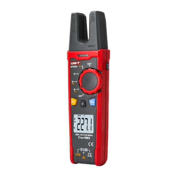
UT256A User Manual UT256A User Manual V. External Structure (Picture 1) IV. Electrical Symbols 1. NCV sensor Symbol Description 2. Open jaw fork Direct current 3. Flashlight LED light 4. Hand guard Alternating current Visual NCV alarm indicator Earth (ground) TERMINAL 6. -
Page 6: Lcd Display
UT256A User Manual UT256A User Manual VI. LCD Display (Picture 2) VII. Function Buttons 1.SELECT button: When the function switch is in the composite function position, short press this button to switch between the corresponding functions. 2.H/ button: Short press this button to enable/disable the data hold function. -
Page 7: Operating Instructions
UT256A User Manual UT256A User Manual 2. AC Voltage/Frequency Measurement (Picture 4) VIII. Operating Instructions 1) Turn the function switch to the position, and use the 1. AC Current/Frequency Measurement (Picture 3) SELECT button to switch to AC voltage/frequency 1) Turn the function switch to the position, and use the measurement. - Page 8 UT256A User Manual UT256A User Manual 3. DC Voltage Measurement (Picture 5) Be cautious to avoid electric shock when measuring high voltages. 1) Turn the function switch to the position. Before each use, verify meter operation by measuring a 2) Insert the red test lead into the signal input jack, black into known voltage.
- Page 9 UT256A User Manual UT256A User Manual Caution: Do not input voltages higher than DC 60V or AC 30V to avoid personal injury. Before measuring the resistance online, switch off the power supply of the circuit, and fully discharge all capacitors to ensure accurate measurement.
-
Page 10: Specifications
UT256A User Manual UT256A User Manual To disable the auto power off function, press and hold the i. Auto power off: 15 minutes (can be disabled) SELECT button in the off state, and then turn on the j . Dimensions: 220mm×58.5mm×38mm meter. - Page 11 UT256A User Manual UT256A User Manual 1) AC Current/Frequency 2) Voltage AC voltage/frequency Range Accuracy Resolution Range Accuracy Resolution 0.2A ≤ACA ≤2.0A: 6.000V 0.001V ± (1.8%+2) 60.00V 0.01V 2.0A <ACA ≤5.0A: ± (1.2%+3) 200.0A 0.1A 600.0V 0.1V ± (1.8%+3) 1000V 5.0A <ACA ≤200.0A:...
-
Page 12: Maintenance
UT256A User Manual UT256A User Manual The AC crest factor of a non-sinusoidal wave decreases 5) Audio/Visual alarm indicator linearly to about 1.8 at 6000 counts. The additional error Description should be added for the corresponding crest factor as Function... - Page 13 UT256A User Manual UT256A User Manual 3) The maintenance and service must be implemented by qualified professionals or designated departments. 2. Battery Replacement (Picture 8) 1) Turn off the meter and remove the test leads from the input jacks. 2) Unscrew and remove the battery cover.