NCR Tri-Light 7709 Kit Instructions
Hide thumbs
Also See for Tri-Light 7709:
- Kit instructions (18 pages) ,
- Instructions manual (12 pages) ,
- Kit instructions (8 pages)
Table of Contents
Advertisement
Quick Links
Advertisement
Table of Contents

Related Manuals for NCR Tri-Light 7709


Summary of Contents for NCR Tri-Light 7709
- Page 1 Kit Instructions Tri-Light (7709) 7709-K801 Issue A...
- Page 2 NCR, therefore, reserves the right to change specifications without prior notice. All features, functions, and operations described herein may not be marketed by NCR in all parts of the world. In some instances, photographs are of equipment prototypes. Software screen images are representative, and in some cases, may not match a customer’s installed software exactly.
-
Page 3: Revision Record
Revision Record Issue Date Remarks May 2022 First Issue... - Page 5 Tri-Light (7709) This publication provides procedures for installing the Tri-Light kit on an NCR SelfServ™ 90 (7709) Kiosk unit. This kit is compatible with NCR 7709 release versions R2.0 and R2.1 only. Note: This kit requires the 7364-K062 Tri-Light/Lane Light Pole and Mount kit.
-
Page 6: Kit Contents
Tri-Light (7709) Kit Contents Part Number Description 497-0526700 Kit, Tri-Light, 7709 006-8615143 Cable Tie, 142 x 3.6 mm 006-8624019 Bag - Poly 13" x 16" 2 Mil, Non-Sealable 009-0024464 Cable Assembly - USB Type A Extension 1.8m - High Speed (480Mbps) 497-0423108 Instructions-Kit (Reference Sheet) -
Page 7: Installation Procedure
Tri-Light (7709) Installation Procedure To install the Tri-Light kit, follow these steps: 1. Shutdown and power off the terminal. 2. Disconnect the Kiosk AC Power Cable from the outlet. 3. To open the kiosk, insert the key into the lock at the right-hand side of the kiosk, turn the key clockwise, and carefully open the front of the kiosk. - Page 8 Tri-Light (7709) 7. Adjust the jumper settings based on the following: • For J2, place the shunt over Pins 5, 6. • For J7, place the shunt over Pins 5, 6. • For J20, place the shunt over Pins 1, 2 and Pins 5, 6. •...
- Page 9 Power Supply 2-pin Connector Note: This connector is not connected to the I/O Adapter if the NCR 7709 unit is using the Indicator Light. 11. Route the Tri-Light/Lane Light Extender Cable from the I/O Adapter to the top of the Tri-Light/Lane Light Pole. For more information, refer to...
- Page 10 Tri-Light (7709) 12. Connect the Tri–Light/Lane Light Assembly Cable to the Tri-Light/Lane Light Extender Cable.
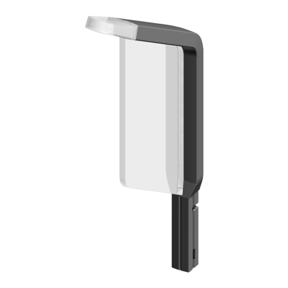
- Page 11 Tri-Light (7709) 13. With the Lane Light facing the front of the kiosk, insert the Tri-Light/Lane Light Assembly into the pole. Caution: Ensure that the cables are not pinched.
- Page 12 Tri-Light (7709) 14. Align the mounting holes of the Tri-Light/Lane Light assembly and the pole, and then secure the assembly to the pole using the screw included in the 7364-K801 kit.
-
Page 13: Removing The Power Supply
Tri-Light (7709) Removing the Power Supply 1. Remove and set aside the nut and the Closed P-Loop Clamp securing the AC Power Cable above the Power Supply. 2. Disconnect the AC Power Cable from the Power Supply. 3. Unstrap the cinch strap that secures the Power Supply to the bracket, and then remove the Power Supply from its bracket. - Page 14 Tri-Light (7709) Removing the I/O Adapter 1. Loosen the hex nut that secures the I/O Adapter Bracket to the kiosk, and then remove the I/O Adapter Assembly from its two mushroom studs. 2. Remove the side cover bracket by removing the two M3 screws.
- Page 15 Tri-Light (7709) 3. Remove the I/O Board from its bracket by removing the four M3 screws. Installing the I/O Adapter 1. Mount the I/O Board onto its bracket and secure with four M3 screws. 2. Install the side cover bracket and secure with two M3 screws.
- Page 16 Tri-Light (7709) 3. Position the I/O Adapter Assembly onto its hex nut and mushroom studs, and then tighten the hex nut to secure the I/O Adapter Bracket to the kiosk.
-
Page 17: Installing The Power Supply
Tri-Light (7709) Installing the Power Supply 1. Mount Power Supply to the bracket and secure with the Cinch Strap. 2. Connect the AC Power Cable to the power supply. 3. Insert the AC Power Cable into the cable clamp, and then secure the clamp to the cabinet using a nut. - Page 18 Tri-Light (7709) Routing the Tri-Light/Lane Light Extender Cable 1. If already installed on the kiosk, remove the Tri-Light/Lane Light Pole from its mount. a. Remove the screw that secures the Tri-Light/Lane Light Pole to the kiosk cabinet. b. Pull the pole out of its mount.
- Page 19 Tri-Light (7709) 2. Route the Tri-Light/Lane Light Extender Cable out of the cable access hole at the top of the kiosk cabinet. 3. Insert the extender cable through the cable access hole on the front of the pole and route it out the top of the pole. Tip: To easily route the extender cable through the pole, follow these steps: a.
- Page 20 Tri-Light (7709) 4. Insert the pole into its mount and secure it with its mounting screw. Caution: Ensure that the extender cable is not pinched. 5. Route the extender cable through the p-loops shown in the following image.