Advertisement
Quick Links
Advertisement

Related Manuals for NCR SelfServ 90 R1.2


Summary of Contents for NCR SelfServ 90 R1.2
- Page 1 Kit Instructions Datalogic 1500i Scanner (R1.2 and R2.0) 7709-K534 Issue A...
- Page 2 NCR, therefore, reserves the right to change specifications without prior notice. All features, functions, and operations described herein may not be marketed by NCR in all parts of the world. In some instances, photographs are of equipment prototypes. Software screen images are representative, and in some cases, may not match a customer’s installed software exactly.
- Page 3 Revision Record Issue Date Remarks Sep 2020 First Issue...
- Page 5 Datalogic 1500i Scanner (R1.2 and R2.0) This publication provides procedures for upgrading the NCR SelfServ™ 90 (7709) Kiosk R1.2 and R2.0 Imaging Scanner from Honeywell 7580G to Datalogic 1500i.
-
Page 6: Kit Contents
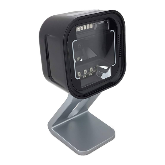
Datalogic 1500i Scanner (R1.2 and R2.0) Kit Contents Part Number Description 497-0528577 Kit - Datalogic 1500i Scanner, R2.1 497-0528580 Scanner, Datalogic Magellan 1500i with Base Cover, Black 497-0528564 Cable, USB Type A to RJ50, Magellan 1500i Imager, 410mm 497-0528525 Bracket, Imager, 7709 009-0007087 Serrated Nut, M4, Self Locking (3 pcs) 006-8615143 Cable Tie, 142 mm x 3.6 mm 006-8623359 Bag, 2x2 Zip Lock... - Page 7 Datalogic 1500i Scanner (R1.2 and R2.0) NCR 7709 R1.2 Installation Procedure This sections provides the installation procedure for NCR SelfServ 90 Kiosks with PID 7709-2200-8090. Warning: Disconnect the AC power cord before disassembling the kiosk. 1. Shutdown and power off the terminal. Disconnect the Kiosk AC Power Cable from the outlet.
- Page 8 Datalogic 1500i Scanner (R1.2 and R2.0) 3. Remove the Honeywell 7580G Imaging Scanner assembly from the kiosk. a. Disconnect the Imaging Scanner Cable from the motherboard, and cut off the cable ties securing the cables routed on the Imaging Scanner bracket. b. Remove the three nuts securing the Imaging Scanner to the kiosk and then lift the Imaging Scanner out of its mounting area.
- Page 9 Datalogic 1500i Scanner (R1.2 and R2.0) 4. Install the Datalogic 1500i Imaging Scanner assembly. a. Mount the Imaging Scanner onto the Imager bracket. Ensure that it sits tightly into the slot, as shown in the following image.
- Page 10 Datalogic 1500i Scanner (R1.2 and R2.0) b. Mount the Imaging Scanner assembly over the Imager Shield. ! Important: On the front side of the fascia, make sure that all sides of the Imager Scan Window is flush against the sides of the Imager Shield. Adjust the alignment of the Imager accordingly.
- Page 11 Datalogic 1500i Scanner (R1.2 and R2.0) d. Connect one end of the Imaging Scanner cable to the bottom of the Imaging Scanner and connect the other end to the USB B port of the motherboard.
- Page 12 Datalogic 1500i Scanner (R1.2 and R2.0) e. Route and tuck the following cables together on the left side of the Imaging Scanner assembly and use a cable tie to secure the cables to the cable management slot shown in the following image. •...
- Page 13 Datalogic 1500i Scanner (R1.2 and R2.0) NCR 7709 R2.0 Installation Procedure This sections provides the installation procedure for NCR SelfServ 90 Kiosks with PID 7709-3000-8090 and 7709-4000-8090. Warning: Disconnect the AC power cord before disassembling the kiosk. 1. Shutdown and power off the terminal. Disconnect the Kiosk AC Power Cable from the outlet.
- Page 14 Datalogic 1500i Scanner (R1.2 and R2.0) 3. Remove the Honeywell 7580G Imaging Scanner. a. Disconnect the Imaging Scanner Cable from the motherboard, and cut off the cable ties securing the cables routed on the Imaging Scanner bracket. b. Remove the three nuts securing the Imaging Scanner to the kiosk and then lift the Imaging Scanner out of its mounting area.
- Page 15 Datalogic 1500i Scanner (R1.2 and R2.0) 4. Install the Datalogic 1500iImaging Scanner assembly. a. Mount the Imaging Scanner onto the Imager bracket. Ensure that it sits tightly into the slot, as shown in the following image.
- Page 16 Datalogic 1500i Scanner (R1.2 and R2.0) b. Mount the Imaging Scanner assembly over the Imager Shield. ! Important: On the front side of the fascia, make sure that all sides of the Imager Scan Window is flush against the sides of the Imager Shield. Adjust the alignment of the Imager accordingly.
- Page 17 Datalogic 1500i Scanner (R1.2 and R2.0) d. Connect one end of the Imaging Scanner cable to the bottom of the Imaging Scanner and connect the other end to the USB B port of the motherboard. e. Route and tuck the following cables together on the left side of the Imaging Scanner assembly and use a cable tie to secure the cables to the cable management slot shown in the following image.