
Related Manuals for Sony Jumbotron JME-UA200


Summary of Contents for Sony Jumbotron JME-UA200
- Page 1 SERVICE MANUAL MODEL DEST......JME-UA200 World UNIT ALIGNMENT CONTROLLER...
- Page 2 CRITICAL TO SAFE OPERATION. REPLACE THESE COMPO- LES SCHÉMAS DE PRINCIPE, LES VUES EXPLOSÉES ET LES NENTS WITH SONY PARTS WHOSE PART NUMBERS APPEAR LISTES DE PIECES SONT D’UNE IMPORTANCE CRITIQUE AS SHOWN IN THIS MANUAL OR IN SUPPLEMENTS PUB- POUR LA SÉCURITÉ...
-
Page 4: Table Of Contents
TABLE OF CONTENTS OPERATING INSTRUCTIONS ............1-1(E) SERVICE INFORMATIONS 2-1. Circuit Boards Location ................2-1(E) 2-2. Disassembly 2-2-1. Switching Regulator and UCI Board Removal ......... 2-2(E) 2-2-2. UCM, UCK Boards and Liquid Crystal Indicate Panel Removal ..2-3(E) CIRCUIT ADJUSTMENTS 3-1. -
Page 5: Operating Instructions
3-864-807-11 (1) JumboTron Unit Alignment Controller Operating Instructions Before operating the unit, please read this manual thoroughly and retain it for future reference. JME-UA200 © 1998 by Sony Corporation Sony Corporation Printed in Japan... - Page 6 Record the serial number in the space provided below. the limits for a Class A digital device, pursuant to Part 15 of Precautions ................ 4 Refer to these numbers whenever you call upon your Sony the FCC Rules. These limits are designed to provide dealer regarding this product.
-
Page 7: About This Manual
Overview of the JumboTron System About This Manual The JumboTron system displays video images on a large screen This instruction manual is mainly aimed at the maintenance/service (JumboTron screen) located either outdoors or indoors. Images from video personnel. sources such as a VCR, video camera and computer can be displayed on It explains how to use the JME-UA200 unit alignment controller, which is the screen. - Page 8 Overview of the JumboTron System Structure of the JumboTron screen Configuration of the JumboTron system Two types of the JumboTron screen are available. One is the conventional The following is the suggested configuration of the JumboTron system. CRT type screen in which light emitting bodies of three primary colors (R, G and B), “Trinilite,”...
-
Page 9: Features
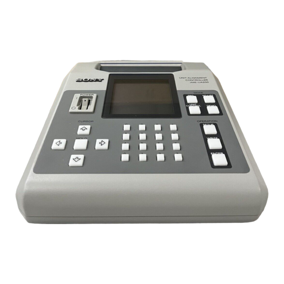
Features Locations and Functions of Parts and Controls The JME-UA200 unit alignment controller is designed to adjust the Front panel luminance of a JumboTron display unit, cell or pixel and to check their operations. The main functions of the JME-UA200 are as follows: Eleven types of test signals The built-in test signal generator of the controller displays eleven types of test signals, allowing you to check various circuits and functions of a... -
Page 10: Connections
Connections Locations and Functions of Parts and Controls Rear panel Connecting a JumboTron display unit Connect a JumboTron display unit to the SIGNAL OUT connector. When measuring the luminance or making an automatic luminance adjustment, connect a sensor (not supplied) to the SENSOR connector. Be sure to turn off the power of the controller before connecting the sensor. -
Page 11: Displaying A Test Signal On A Jumbotron Display Unit
Displaying a Test Signal on a JumboTron Display Unit You can display eleven types of test signals on a JumboTron display unit. 1 Selecting the test signal to be displayed Use this mode to clear the cause of the malfunctions of a unit or to check the operation of a unit, cell or pixel after replacing or adjusting it. - Page 12 Displaying a Test Signal on a JumboTron Display Unit 2 Specifying the luminance, brightness, scroll speed and color bar width of the Items to be specified selected test signal Adjustable range Items JTU-35, JTU-17 LDU-15 Specify after displaying the test signal on the JumboTron display unit by 256 levels in the range from 00 LUM (Luminance) 1024 levels in the range...
-
Page 13: Adjusting The Luminance Manually
Adjusting the Luminance Manually This section explains how to adjust the luminance manually in accordance LDU-15 with the menu in the display window. You can adjust the luminance each Adjustment mode Adjustment of the unit, cell and pixel , allowing you to obtain uniform luminance of If-White Changes the luminance level of white (three colors the whole screeen. - Page 14 Adjusting the Luminance Manually Press the ◊ or √ button to select the type of the JumboTron display unit 2 Selecting the target of luminance adjustment and setting the unit to the proper you are using, then press the ENTER button. brightness level for carrying out the adjustment Press the ADJUST button.
- Page 15 Adjusting the Luminance Manually Numbering the position of a cell Press the ENTER button to finish the setting. The selected target of adjustment, luminance and brightness data are LDU-15 stored in the memory. The display returns to the MANUAL ADJUST JTU-35, JTU-17 : 01 : 02...
-
Page 16: Adjusting The Luminance Automatically Using A Sensor
Adjusting the Luminance Automatically Using a Sensor Adjusting the Luminance Manually The adjustable range of the data is as follows: Connect the sensor (not supplied) to the unit alignment controller. (See page 11 for connection.) Adjustment mode Adjustable range of the data Unit type First, attach the sensor to a cell with correct luminance and make the JTU-35... - Page 17 Adjusting the Luminance Automatically Using a Sensor Numbering the position of a cell Press the ADJUST button. A D J U S T M E N U JTU-35, JTU-17 LDU-15 M A N U A L : 01 : 02 : 03 : 04 : 01...
- Page 18 Adjusting the Luminance Automatically Using a Sensor Press the ENTER button. Attach the sensor (not supplied) to the target cell and press the ENTER button. The measured data is stored in the memory, and the SENSOR ADJUST menu is restored. The luminance is automatically measured.
-
Page 19: Checking The Jumbotron Display Unit Functions
Checking the JumboTron Display Unit Functions You can check whether the JumboTron display units are operating Set the POWER switch to ON. properly or not, or check the current condition of a unit. The title menu appears in the display window, then the display changes You can select from among eight check modes as shown below. -
Page 20: Checking The Operation Of The Indicator On The Rear Of A Jumbotron Display Unit (Led Check)
Checking the JumboTron Display Unit Functions Checking the operation of the indicator on the rear of a JumboTron Checking the blinking or lighting operation of a JumboTron display unit display unit (LED Check) (Cursor Check Menu) Check if the indicator lights, blinks or turns off correctly. Check if a unit or cell blinks correctly. -
Page 21: Checking The Operation Of The Test Signal Generator In A Jumbotron Display Unit (Unit Spg)
Checking the JumboTron Display Unit Functions Checking the operation of the test signal generator in a JumboTron Checking the communication between the controller and a JumboTron display unit (UNIT SPG) display unit (Ask UNIT Type) Select UNIT SPG from the UNIT CONTROL menu. To check whether the communication between the controller and a specified unit is correct or not, the controller sends the unit a signal to ask The UNIT SPG menu appears in the display window. -
Page 22: Checking The Revised Light Emission Data Of Each Dot, Hv Current Value Of A Unit Or A Defictive Cell (Revise Data Menu)
Checking the JumboTron Display Unit Functions Press the ENTER button. Checking the revised light emission data of each dot, HV current value The data of the selected mode appear in the display window. For of a unit or a defictive cell (Revise Data Menu) details, see the respective item below. - Page 23 Checking the JumboTron Display Unit Functions JTU-17 To check the present HV current value (JTU-35, JTU-17 only) G1V: The revised voltage data of each dot for the selected position are displayed. The HV (High Voltage) current of the JumboTron display unit is measured Press ∫...
-
Page 24: Checking The Present Conditions Of The Jumbotron Display Unit (Unit Condition) (Ldu-15 Only)
Specifications Checking the JumboTron Display Unit Functions Power requirements 100 to 240 V AC, 50/60 Hz Checking the present conditions of the JumboTron display unit (Unit Current consumption 0.2 A Condition) (LDU-15 only) 200 × 240 × 90 mm Dimensions ×... -
Page 25: Service Informations
SECTION 2 SERVICE INFORMATIONS 2-1. CIRCUIT BOARDS LOCATION Liquid crystal indicate panel Switching regulator JME-UA200 2-1(E) -
Page 26: Disassembly
2-2. DISASSEMBLY 2-2-1. Switching Regulator and UCI Board Removal 4 Front panel assembly 8 Two screws (+PSW 3 X 5) 5 Four screws 9 UCI board (+PSW 3 X 5) 1 Two screws (+B 3 X 6) 6 Switching regulator 7 Four screws 3 Two screws (+B 3 X 6) -
Page 27: Ucm, Uck Boards And Liquid Crystal Indicate Panel Removal
2-2-2. UCM, UCK Boards and Liquid Crystal Indicate Panel Removal 1 Four screws UCK board (+PSW 3 X 5) 2 UCM board 3 Ten screws (+PSW 3 X 5) 4 UCK board Extension cable (A-1501-423-A) 5 Four screws UCK board (+PSW 2.5 X 6) 6 Liquid crystal indicate panel... -
Page 29: Circuit Adjustments
SECTION 3 CIRCUIT ADJUSTMENTS 3-1. LCD CONTRAST ADJUSTMENT 3-3. CHECKING IN UNIT CONTROL MODE 1. Start up the JME-UA200, and make adjustment under the condition of Menu screen shown below. (Fig. 1) Connect the LDU-15, and make the following checking in 2. -
Page 31: Circuit Descriptions
SECTION 4 CIRCUIT DESCRIPTIONS RXD0 TXD1 IC35 RXD1 LINE From UNIT RECEIVER MATRIX IC40 IC53 MODUL DRIVER/ To PC RECEIVER IC51 PROGRAM IC54 ı DATA MD15 SRAM 18.88MHz CLOCK ı ADDRESS IC4-10 NTSC MA19 IC52 COUNTER FLASH MEMORY 18.75MHz CLOCK IC13,14 IC11,12 IC31,32... -
Page 32: Unit Control Mode
4-3. UNIT CONTROL MODE Same as in ADJUST mode, the unit control commands are inserted in the control data blocks and transmitted to the unit. In making inquiry for model name or brightness correc-tion value to the unit, if the control data are transmitted, the inquired data are returned from the unit in the ASCII codes of serial data at 4800bps for JTU-35/17 Series, or 9600pbs for LDU-15 Series. -
Page 33: Semiconductors
IC, DIODE SECTION 5 SEMICONDUCTORS DS26C31TM IDT7024L25PF TC74AC00F DS26C32ATM IDT7027L55PF TC74AC02F TC74AC04F TC74AC20F TC74AC574F-EL TC74AC74F TC74AC86F TOP VIEW TOP VIEW 16pin DIP DS26C31TMX DS26C32ATMX 100pin QFP TOP VIEW TC74AC138F MAX233ACWP TC74AC161F SC370605D TC74AC163F TC74AC541F TC74AC541F-EL TC74AC574F 14pin SOP WS57C43C-35 TOP VIEW TOP VIEW TOP VIEW 16pin SOP... -
Page 35: Exploded Views
SECTION 6 EXPLODED VIEWS NOTE: • Items with no part number and no description are not stocked because they are seldom required for routine service. • The construction parts of an assembled part are indicated with a collation number in the remark column. •... -
Page 36: Chassis
CHASSIS 6-1. CHASSIS : 7-682-547-09 +B3x6 : 7-682-946-09 +PSW3x5 : 7-682-348-09 +RK3x8 : 7-682-961-01 +PSW4x8 : 7-621-763-45 +PSW2.5x6 Rf.No. Part No. Description Remark Rf.No. Part No. Description Remark 3-681-054-11 POWER SW GUARD * A-1390-832-A UCK BOARD, MOUNT 3-688-814-31 CAP, SWITCH * A-1390-829-A UCI BOARD, MOUNT ! 1-570-117-51 SWITCH, SEESAW (AC POWER) * 4-065-008-01 HANDLE... -
Page 37: Electrical Parts List
UCI UCK SECTION 7 Rf.NO. PART NO. DESCRIPTION REMARK Rf.NO. PART NO. DESCRIPTION REMARK ELECTRICAL PARTS LIST NOTE: • Items marked " * " are not stocked since RESISTORS The components identified ! marked are they are seldom required for routine •... - Page 38 UCK UCM Rf.NO. PART NO. DESCRIPTION REMARK Rf.NO. PART NO. DESCRIPTION REMARK <DIODE> 1-162-917-11 CERAMIC CHIP 15PF 1-162-917-11 CERAMIC CHIP 15PF D201 8-719-800-76 DIODE 1SS226 D202 8-719-800-76 DIODE 1SS226 1-162-917-11 CERAMIC CHIP 15PF D203 8-719-800-76 DIODE 1SS226 1-128-397-21 ELECT CHIP 100MF D204 8-719-800-76 DIODE 1SS226...
- Page 39 Rf.NO. PART NO. DESCRIPTION REMARK Rf.NO. PART NO. DESCRIPTION REMARK 1-164-004-11 CERAMIC CHIP 0.1MF IC29 8-759-244-85 IC TC74AC574F 1-164-004-11 CERAMIC CHIP 0.1MF IC30 8-759-244-85 IC TC74AC574F 1-164-004-11 CERAMIC CHIP 0.1MF IC31 8-759-562-91 IC WS57C43C-35-1010H 1-164-004-11 CERAMIC CHIP 0.1MF IC32 8-759-562-92 IC WS57C43C-35-1010L 1-164-004-11 CERAMIC CHIP 0.1MF IC33 8-759-562-93 IC EPM7064LC44-15-PSCV...
- Page 40 Rf.NO. PART NO. DESCRIPTION REMARK Rf.NO. PART NO. DESCRIPTION REMARK 1-216-097-91 RES, CHIP 100K 1/10W ! 1-570-117-51 SWITCH, SEESAW (AC POWER) 1-216-097-91 RES, CHIP 100K 1/10W 1-691-364-21 CONNECTOR, FFC/FPC (ZIF) 26P 1-216-097-91 RES, CHIP 100K 1/10W ************************************************************************************ 1-216-097-91 RES, CHIP 100K 1/10W 1-216-097-91 RES, CHIP...
-
Page 41: Block Diagram
UCI, UCK, UCM UCI, UCK, UCM SECTION 8 BLOCK DIAGRAM IC50 UCM (MAIN BOARD) SENSOR CONTROL IC40 CLS0, CLS1 CLS0, 1 CLS0, 1 A0-7 IC55 1, 2 MICRO CONTROLLER SS0, SS1 SYSTEM FILTER SS0, 1 SS0, 1 3, 4 RESET SENSOR BLSO-BLS3 19.660MHz... -
Page 43: Diagrams
SECTION 9 DIAGRAMS 9-1. SCHEMATIC DIAGRAMS AND PRINTED WIRING BOARDS Note: • All capacitors are in µF unless otherwise noted. pF: µµF 50 WV or less are not indicated except for electrolytics. • All electrolytics are in 50 V unless otherwise specified. •... - Page 44 – A SIDE – – B SIDE – SUFFIX: -11 SUFFIX: -11 UCM BOARD *: B SIDE *E-2 IC21 *E-2 IC41 *C-1 IC22 IC42 *D-1 IC23 IC43 *D-2 *F-3 IC24 IC44 *B-1 *F-3 IC25 IC45 *C-1 IC26 IC46 *D-2 *F-4 IC27 IC47 *B-2...
- Page 45 UCM-P1 BOARD IC4-6, 10 TC74AC161F UCM-P1, P2, P4, P5 BOARDS IC11-14, 25-28, 41-43, 46-49 TC74AC541F RIPPLE ENABLE CARRY OUTPUT CLEAR LOAD ENABLE UCM-P1, P2, P4 BOARDS IC7, 29, 30, 50 TC74AC574F UCM-P1 BOARD IC18 TC74AC138F DATA OUTPUTS OUTPUT SELECT ENABLE JME-UA200...
- Page 46 UCM-P1 UCM-P1 DMA17 IC10 TC74AC161F TC74AC574F TC74AC163F TC74AC163F TC74AC161F TC74AC161F SYNC BINARY SYNC BINARY SYNC BINARY SYNC BINARY SYNC BINARY TC74AC161F SYNC BINARY IC1(4/6) COUNTER COUNTER COUNTER COUNTER COUNTER SYNC BINARY TC74AC04F COUNTER INVERTER COUNTER IC1(3/6) TC74AC04F INVERTER DMA6 DMA7 DMA11 DMA15 DMA2...
- Page 47 UCM-P2 UCM-P2 TO P1 IC33 EPM7064LC44-15 U-RTN + PARALLEL-SERIAL CONVERTOR SO 1 + SO 2 + SO 3 + SO 4 + :CHIP U-RTN - SO 1 - SO 2 - SO 3 - SO 4 - IC34 DS26C31TMX LINE DRIVER CLS0 CLS0 CLS1...
- Page 48 UCM-P3 UCM-P3 RD/HWR D0-D15 A0-A14 A0-A14 DMA9 DMA10 A10L A10R DMA11 A11L A11L DMA12 A12L A12L DMA13 A13L A13L DMA14 A14L A14L IC39 IC38 IDT7024L25PF INTL IDT7027L55PF FN DATE RAM CE0L CE0R BUSYL IMAGE DATE RAM CE1L CE1R SEML SEMR BUSYR R/WL R/WR...
- Page 49 UCM-P4 UCM-P4 :CHIP 22k :CHIP :CHIP :CHIP IC48 :CHIP IC50 TC74AC541F-EL TC74AC574F-EL KEY DATA BUFFER SENSOR CONTROL :CHIP :CHIP KEY SCAN OUT KEY SCAN OUT CLS0 KEY SCAN OUT CLS1 KEY SCAN OUT KEY SCAN OUT TO P2 KEY SCAN OUT BLS0 KEY SCAN OUT BLS1...
- Page 50 UCM-P5 UCM-P5 B:CHIP B:CHIP B:CHIP B:CHIP B:CHIP B:CHIP B:CHIP B:CHIP B:CHIP B:CHIP B:CHIP B:CHIP B:CHIP IC41 TC74AC541F-EL ADDRESS BUFFER B:CHIP B:CHIP 100k :CHIP 100k :CHIP B:CHIP B:CHIP B:CHIP B:CHIP B:CHIP B:CHIP B:CHIP B:CHIP B:CHIP B:CHIP B:CHIP B:CHIP B:CHIP B:CHIP 100k :CHIP 100k :CHIP 100k :CHIP B:CHIP...
- Page 51 1SS123 SURGE PROTECTION U-RTIN + LINE FILTER SO 1 + U-RTN + SO 1 + SO 1 + 1SS123 U-RTIN + U-RTN + SO 1 + SURGE SO 1 - SO 1 - SO 1 + SO 2 + PROTECT DIODE SO 1 + SO 2 + SO 2 +...
- Page 52 – A SIDE – – B SIDE – SUFFIX: -11 SUFFIX: -11 9-10 9-10 JME-UA200...
- Page 53 LAN0 KEY SCAN OUT D201 S201 S208 S215 S222 1SS123 KEY SCAN OUT SURGE LAN1 PROTECTION KEY SCAN OUT D202 LAN0 1SS123 KEY SCAN OUT SURGE ADJUST LAN2 PROTECTION KEY SCAN OUT D203 S202 S209 S216 S223 1SS123 KEY SCAN OUT SURGE LAN3 PROTECTION...
- Page 56 English/Japanese 98HY05028-1 Sony Corporation Printed in Japan Broadcasting & Professional Systems Company © 1998. 8 9-976-691-01...