
Related Manuals for Sony JumboTron


Summary of Contents for Sony JumboTron
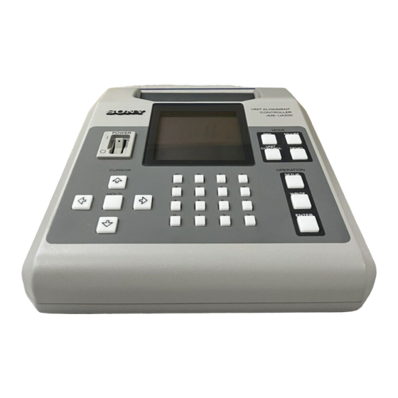
- Page 1 3-864-807-13 (1) JumboTron Unit Alignment Controller Operating Instructions Before operating the unit, please read this manual thoroughly and retain it for future reference. JME-UA200 © 1998 by Sony Corporation...
- Page 2 Record the serial number in the space provided below. the limits for a Class A digital device, pursuant to Part 15 of Refer to these numbers whenever you call upon your Sony the FCC Rules. These limits are designed to provide dealer regarding this product.
-
Page 3: Table Of Contents
About This Manual ............. 4 Precautions ................ 4 Overview of the JumboTron System ........ 5 Images to be displayed on the JumboTron screen ....5 Structure of the JumboTron screen ......... 6 Configuration of the JumboTron system ......... 8 Features ................9 Locations and Functions of Parts and Controls Locations and Functions of Parts and Controls ... -
Page 4: About This Manual
About This Manual This instruction manual is mainly aimed at the maintenance/service personnel. It explains how to use the JME-UA200 unit alignment controller, which is used to adjust and inspect the JumboTron display units of the JumboTron system. Precautions On safety •... -
Page 5: Overview Of The Jumbotron System
Images to be displayed on the JumboTron screen The JumboTron system can display the following three types of images: [a] Video images input from equipment such as a VCR, video camera... -
Page 6: Structure Of The Jumbotron Screen
The basic element of the JumboTron screen is an RGB trio (dot). A “cell” consists of the dots arranged at a certain interval (picture element pitch) and a “unit (JumboTron display unit)” consists of 12 cells for the CRT type and 16 cells for the LED type. - Page 7 4 dots Unit Front panel 4 cells 4 cells (16 dots) (8 dots) 4 cells (16 dots) 4 cells (16 dots) JumboTron screen Unit NTSC: max. 30 units (120 cells = 480 2 panels dots) (16 dots) PAL: max. 36 units...
-
Page 8: Configuration Of The Jumbotron System
Overview of the JumboTron System Configuration of the JumboTron system The following is the suggested configuration of the JumboTron system. Control room Screen site JME-UA200 unit alignment JumboTron screen controller Audio mixer Microphone Computer JTA-LS200 ABC sensor unit Audio amplifier... -
Page 9: Features
Features The JME-UA200 unit alignment controller is designed to adjust the luminance of a JumboTron display unit, cell or pixel and to check their operations. The main functions of the JME-UA200 are as follows: Eleven types of test signals The built-in test signal generator of the controller displays eleven types of test signals, allowing you to check various circuits and functions of a JumboTron display unit. -
Page 10: Locations And Functions Of Parts And Controls
7 Numeric buttons SPG (Signal Pattern Generator) button: Displays a Inputs the data in hexadecimal. test signal on a JumboTron display unit. You can select and display the desired signal among eleven signals; WHITE, BLUE, RED, GREEN, STAIR STEP, COLOR BAR-V (vertical color bar), COLOR BAR-H (horizontal color bar), CHARACTERS, BEAM BLANKING, TEST and RASTER. -
Page 11: Rear Panel
Rear panel AC IN SIGNAL OUT SENSOR 1 SIGNAL OUT connector (D-sub 15-pin) Connect a JumboTron display unit to be adjusted. 2 COM connector (D-sub 9-pin) Connect a computer to display the data for demonstration. 3 SENSOR connector (Half-pitch 20-pin) Connect a unit alignment sensor (not supplied). -
Page 12: Connections
Connections Connecting a JumboTron display unit Connect a JumboTron display unit to the SIGNAL OUT connector. When measuring the luminance or making an automatic luminance adjustment, connect a unit alignment sensor (not supplied) to the SENSOR connector. Be sure to turn off the power of the controller before connecting the sensor. -
Page 13: Displaying A Test Signal On A Jumbotron Display Unit
Displaying a Test Signal on a JumboTron Display Unit You can display eleven types of test signals on a JumboTron display unit. Use this mode to clear the cause of the malfunctions of a unit or to check the operation of a unit, cell or pixel after replacing or adjusting it. - Page 14 L D U - 3 0 S e r i e s G 3 0 S e r i e s Press the ◊ or √ button to select the type of the JumboTron display unit, and press the ENTER button.
- Page 15 2 Specifying the luminance, brightness, scroll speed and color bar width of the selected test signal Specify after displaying the test signal on the JumboTron display unit by steps 1 to 5 above. Press the SETUP button. The items to be specified and their current data (in hexadecimal) appear in the display window.
- Page 16 128: output signal with 128 lines 256: output signal with 256 lines • If you change the CLK setting while the JumboTron display unit is in operation, the unit cannot receive the signal from this controller. In this case, disconnect the unit, then turn on back the power of the unit.
- Page 17 Relation between luminance and brightness BRT (brightness) indicates the adjustable range of the brightness for a JumboTron display unit emitted. LUM (luminance) shows the tone with the set brightness. BRT 0F BRT 0E BRT 0D BRT 0C BRT 0B BRT 0A...
-
Page 18: Adjusting The Luminance Manually
You can adjust the luminance each of the unit, cell and pixel , allowing you to obtain uniform luminance of the whole screeen. There are eleven manual modes for each type of the JumboTron display unit. JTU-35 Adjustment mode Adjustment... - Page 19 LDU-15, LDU-30 Adjustment mode Adjustment If-White Changes the luminance level in white display by changing the current applied to blue, red and green LEDs If-Blue Changes the luminance level in white display by changing the current applied to a blue LED If-Red Changes the luminance level in white display by changing the current applied to a red LED...
- Page 20 L D U - 3 0 S e r i e s G 3 0 S e r i e s Press the ◊ or √ button to select the type of the JumboTron display unit you are using, then press the ENTER button.
- Page 21 Select the manual adjustment mode with the ∫ or ı button, or the 0 to A numberic buttons. The mode changes in the following order each time you press the ∫ button. (Pressing ı button changes the mode in the reverse order.) You can also select the mode by pressing the button in brackets.
- Page 22 Adjusting the Luminance Manually To change the target of adjustment, select “Target” with the ◊ or √ button, then press the ∫ or ı button to change. The display changes in the order of UNIT, CELL and PIXEL each time you press the ∫ button. (It changes in the reverse order each time you press the ı...
- Page 23 3 Selecting cell or pixel to be adjusted When you select CELL or PIXEL as the target of the adjustment, specify the position of the cell or pixel to be adjusted. (If you select UNIT, skip steps 11 and 12.) Press the ENTER button.
- Page 24 Adjusting the Luminance Manually Numbering the position of a cell LDU-30 JTU-35, JTU-17 LDU-15 : 01 : 02 : 03 : 04 : 05 : 06 : 07 : 08 : 01 : 02 : 03 : 04 : 01 : 02 : 03 : 04...
- Page 25 4 Adjusting the luminance Press the ◊ or √ button or the numeric buttons to adjust the luminance to the desired level. Make the adjustment while watching the unit. The adjustment level for the Revise Data (revised data) is displayed only when you adjust the luminance with the numeric buttons.
-
Page 26: Displaying The Luminance Level Before Adjustment/Displaying The Factory Preset Data/Storing The Currently Displayed Data
The adjusted level is stored, and the display returns to the MANUAL ADJUST menu. Do not operate the controller for about 10 seconds after the WRITE button is pressed, as the JumboTron display unit is writing the data into the memory. To restore the level before adjustment without storing the adjusted data Press the SPG button before pressing the WRITE button in step 14. - Page 27 • Load: Factory Data (White) [D]: Displays white by reading the factory preset B, R and G data • Load: Factory Data (Blue) : Displays blue by reading the factory preset B, R and G data • Load: Factory Data (Red) : Displays red by reading the factory preset B, R and G data •...
- Page 28 Adjusting the Luminance Manually Press the ENTER button to finish the setting. The display returns to the MANUAL ADJUST menu. Press the ENTER button again to confirm the mode. The whole unit blinks. M A N U A L A D J U S T L o a d : F a c t o r y D a t a ( W h i t e ) L u m i n a n c e : 0 7 F...
-
Page 29: Adjusting The Luminance Automatically Using A Unit Alignment Sensor (Jtu-35, Ldu-15 And Ldu-30 Only)
Adjusting the Luminance Automatically Using a Unit Alignment Sensor (JTU-35, LDU-15 and LDU-30 Only) This section explains how to adjust the luminance of the cell or front panel automatically by connecting the unit alignment sensor to the unit alignment controller. Procedures vary with the unit alignment sensor you are using. -
Page 30: When Using The Unit Alignment Sensor Jme-Us35C, Jme-Us1515 Or Jme-Us1540
L D U - 3 0 S e r i e s G 3 0 S e r i e s Press the ◊ or √ button to select the type of the JumboTron display unit (JTU-35 Series or LDU-15 Series), and press the ENTER button. - Page 31 The selected cell blinks. Example: Measuring the cell in the top right corner of the unit JumboTron display unit Blinks. S E N S O R M E A S U R E P o s i t i o n S e l e c t...
- Page 32 For fitting the unit alignment sensor, see the Operating Instructions of the sensor. The luminance of the cell where the sensor is fitted is automatically measured. JumboTron display unit Unit alignment sensor JME-UA200 The following display appears. During measurement...
- Page 33 Adjusting the Luminance Automatically First store the correct luminance data in the memory following “Measuring the Correct Luminance” on page 30. Then you can adjust the luminance of the cell to the same level as that of the stored data. Select “Adjust”...
- Page 34 (JTU-35, LDU-15 and LDU-30 Only) Move the unit alignment sensor to the cell where you want to adjust the luminance. Example: Adjusting the cell in the bottom right corner of the unit JumboTron display unit JME-UA200 Unit alignment sensor Press the ENTER button.
- Page 35 About the “Adjust Result” menu The adjustment result of 8 dots for the JTU-35 or 16 dots for the LDU-15 is dislayed on the “Adjust Result” menu. The X symbol means that the adjustment has failed for the corresponding dot. A d j u s t R e s u l t C e l l H : 0 4 V : 0 4 Horizontal dot numbers (H)
-
Page 36: When Using The Unit Alignment Sensor Jme-Us30L
Adjusting the Luminance Automatically Using a Unit Alignment Sensor (JTU-35, LDU-15 and LDU-30 Only) When Using the Unit Alignment Sensor JME-US30L Use the unit alignment sensor JME-US30L for the LDU-30. After setting the front panel to the sensor box, fit the unit alignment sensor to the position of the front panel to be measured where the correct luminance is obtained, and read the data to the unit alignment controller. - Page 37 Press the ◊ or √ button to select SENSOR, and press the ENTER button. S E N S O R A D J U S T Measuring the luminance M e a s u r e Adjusting the luminance A d j u s t Q u i t Finishing U N I T T Y P E : L D U - 3 0...
- Page 38 Adjusting the Luminance Automatically Using a Unit Alignment Sensor (JTU-35, LDU-15 and LDU-30 Only) Fit the unit alignment sensor to the target position of the front panel, and press the ENTER button. For fitting the unit alignment sensor, see the Operating Instructions of the unit alignment sensor.
- Page 39 Adjusting the Luminance Automatically First store the correct luminance data in the memory following “Measuring the Correct Luminance” on page 36. Then you can adjust the luminance of the front panel to the same level as that of the stored data. You can select the target panel position from all the area where the unit alignment sensor is fitted or a specified dot only.
- Page 40 Adjusting the Luminance Automatically Using a Unit Alignment Sensor (JTU-35, LDU-15 and LDU-30 Only) 2 Press the HOLD button. The selected position is stored in the memory and stops blinking. “HOLD!” appears in the display. S E N S O R A D J U S T W a i t i n g S t a r t L U M : 3 F F ( F I X ) B R T : 0 0 7 ( F I X )
- Page 41 When “Dot” is selected The display shows the dot position select menu. S E N S O R A D J U S T P o s i t i o n S e l e c t Luminance of the unit for adjustment L U M : 3 F F ( F I X ) Brightness of the unit for adjustment B R T : 0 0 7 ( F I X )
- Page 42 Adjusting the Luminance Automatically Using a Unit Alignment Sensor (JTU-35, LDU-15 and LDU-30 Only) 4 Press the ENTER button. The luminance of the selected dot is automatically adjusted. The following display appears. During adjustment After adjustment S E N S O R A D J U S T S E N S O R A D J U S T A d j u s t i n g N o w A d j u s t E N D...
- Page 43 About the “Adjust Result” menu The adjustment result for 16 dots is displayed on one page of the Adjust Result menu. The X symbol means that the adjustment has failed for the corresponding dot. By pressing the ENTER button repeatedly, you can change four pages of the Adjust Result menu in sequence, then to the SENSOR ADJUST menu.
-
Page 44: Checking The Jumbotron Display Unit Functions
Checking the JumboTron Display Unit Functions You can check whether the JumboTron display units are operating properly or not, or check the current condition of a unit. You can select from among eight check modes as shown below. Menu in the... - Page 45 L D U - 3 0 S e r i e s G 3 0 S e r i e s Press the ◊ or √ button to select the type of the JumboTron display unit (UNIT Type), and press the ENTER button.
-
Page 46: Resetting The Microprocessor In A Jumbotron Display Unit To Its Initial Condition (Unit Reset)
U N I T R e s e t N o w ! U N I T T Y P E : J T U - 3 5 Checking the operation of the indicator on the rear of a JumboTron display unit (LED Check) Check if the indicator lights, blinks or turns off correctly. - Page 47 Select “LED Check” from the UNIT CONTROL menu. The “LED Check Menu” appears in the display window. JTU-35, JTU-17 U N I T C O N T R O L L E D C h e c k M e n u The indicator blinks.
-
Page 48: Checking The Blinking Or Lighting Operation Of A Jumbotron Display Unit (Cursor Check Menu)
Checking the JumboTron Display Unit Functions Checking the blinking or lighting operation of a JumboTron display unit (Cursor Check Menu) Check if a unit or cell blinks correctly. You can set the display color of a unit which does not blink to white or black. Check also if the frame of the unit lights correctly. -
Page 49: Checking The Operation Of The Test Signal Generator In A Jumbotron Display Unit (Unit Spg)
Checking the operation of the test signal generator in a JumboTron display unit (UNIT SPG) Select UNIT SPG from the UNIT CONTROL menu. The UNIT SPG menu appears in the display window. U N I T C O N T R O L... -
Page 50: Checking The Communication Between The Controller And A Jumbotron Display Unit (Ask Unit Type)
Checking the JumboTron Display Unit Functions Checking the communication between the controller and a JumboTron display unit (Ask UNIT Type) To check whether the communication between the controller and a specified unit is correct or not, the controller sends the unit a signal to ask for the type of the unit. -
Page 51: Checking The Revised Light Emission Data Of Each Dot, Hv Current Value Of A Unit Or A Defective Cell (Revise Data Menu)
Checking the revised light emission data of each dot, HV current value of a unit or a defective cell (Revise Data Menu) Select “Revise Data” from the UNIT CONTROL menu. The “Revise Data Menu” appears in the display window. U N I T C O N T R O L R e v i s e D a t a M e n u Mode to be checked P W M... - Page 52 To check the revised light emission data of each dot The light emission data of each dot in a JumboTron display unit are adjusted to light evenly. You can check the revised data of each dot in the display window.
- Page 53 JTU-17 G1V: The revised voltage data of each dot for the selected position are displayed. Press ∫ button to display the data for four dots on the right, or ı button to display those on the left . Dot number (1–4) Dot number (5–8) Left Right...
- Page 54 U N I T T Y P E : J T U - 3 5 To check for defective cells (JTU-35 and JTU-17 only) The JumboTron display unit checks for defective cell and shows it in the display window. In step 2 on page 51, set “SCREEN No.” (JTU-17 only) and “UNIT Address,”...
-
Page 55: Checking The Present Conditions Of The Jumbotron Display Unit (Unit Condition) (Ldu-15, Ldu-30 Only)
Checking the present conditions of the JumboTron display unit (Unit Condition) (LDU-15, LDU-30 only) Select “UNIT Condition” from the UNIT CONTROL menu. The “Unit Condition” menu appears in the display window. LDU-15 U N I T C O N T R O L U n i t C o n d i t i o n S c r e e n N o . -
Page 56: Changing The Fan Speed Of A Jumbotron Display Unit
Checking the JumboTron Display Unit Functions Changing the fan speed of a JumboTron display unit (Fan Speed) (LDU- 15 only) Press the ◊ or √ button to select “Fan Speed” from the UNIT CONTROL menu. U N I T C O N T R O L...