
Related Manuals for Cisco Meraki MR20-HW


Summary of Contents for Cisco Meraki MR20-HW
- Page 1 Package Contents The Cisco Meraki MR20-HW package contains the following: • MR20-HW Cloud-Managed Access Point • Mount plate • Mount Kit Wall screws, wall screw anchors, and security screws...
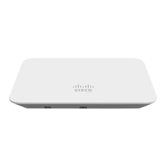
- Page 2 Understanding the MR20-HW Your Meraki MR20-HW has the following features: The mount plate has the following features:...
-
Page 3: Security Features
Security Features The MR20-HW features multiple options for physically securing the access point after installation: 1. Security screw – The accessory kit includes screws that can be used to secure the access point to the mount cradle. Engaging the security screw prevents accidental dislodging and theft. -
Page 4: Pre-Install Preparation
The MR20-HW features a Gigabit Ethernet RJ45 port that accepts 802.3at and 802.3af power (labeled “Eth0, PoE”). This port should be used for uplink to your WAN connection. Power Source Options The MR20-HW access point can be powered using either the Meraki AC Adapter, PoE Injector (both sold separately), or a third-party PoE switch. - Page 5 Check and Upgrade Firmware To ensure your MR20-HW performs optimally immediately following installation, it is recommended that you facilitate a firmware upgrade prior to mounting your MR20-HW. 1. Attach your MR20-HW to power and a wired Internet connection. See the "Power the MR20-HW"...
-
Page 6: Collect Tools
4. Click on the “Uplink Configuration” tab. Log in. The default login is the serial number (e.g. Qxxx-xxxx-xxxx), with no password (e.g., Q2DD-551C-ZYW3). 5. Configure the static IP address, net mask, gateway IP address and DNS servers that this AP will use on its wired connection. 6. -
Page 7: Collect Additional Hardware For Installation
Collect Additional Hardware for Installation You will need the following hardware to perform an installation: Installation Instructions Choose Your Mounting Location A good mounting location is important to getting the best performance out of your MR20-HW access point. Keep the following in mind: 1. - Page 8 3. If being used in a mesh deployment, the MR20-HW should have line of sight to at least two other Meraki devices. A Cisco Partner can help ensure that your AP placement is ideal. Mount the MR20-HW Attach the MR20-HW to the Mount Cradle The MR20-HW attaches to the mount cradle with two tabs on the cradle that insert into the MR20-HW, and is secured to the cradle using one screw.
- Page 9 Power the MR20-HW If mounting to an electrical junction box, feed the Ethernet cable through the cable access hole in the mount cradle. If mounting to a wall or ceiling, the Ethernet cable will feed from behind the MR20-HW. The "Power Source Options"...
-
Page 10: Verify Device Functionality And Test Network Coverage
Then adjust the MR20-HW to guide the MR20-HW’s bottom slot into the cradle’s bottom tab until it clicks into place. Once in place, the MR20-HW should be secured to the cradle by using one of the included screws in the cradle’s bottom tab. Error! Reference source not found. -
Page 11: Troubleshooting
b. Note: Your MR20-HW must have an active route to the Internet to check and upgrade its firmware. 2. Verify access point connectivity a. Use any 802.11 client device to connect to the MR20-HW and verify proper connectivity using the client’s web browser. 3. - Page 12 • Increase the separation between the equipment and receiver. • Connect the equipment into an outlet on a circuit different from which the receiver is connected. • Consult the dealer or an experienced radio/TV technician for help. FCC Caution Any changes or modifications no expressly approved by Meraki could void the user’s authority to operate this equipment.
- Page 13 (i) the device for operation in the band 5150-5250 MHz is only for indoor use to reduce the potential for harmful interference to co-channel mobile satellite systems; (ii) high-power radars are allocated as primary users (i.e. priority users) of the bands 5250-5350 MHz and 5650-5850 MHz and that these radars could cause interference and/or damage to LE-LAN devices.
- Page 14 NCC Compliance Statement...