Endress+Hauser Proline Promag L 400 Brief Operating Instructions
Electromagnetic flowmeter
Hide thumbs
Also See for Proline Promag L 400:
- Operating instructions manual (180 pages) ,
- Operating instructions manual (184 pages)
Table of Contents
Advertisement
Quick Links
KA01113D/06/EN/03.14
71245361
Products
Brief Operating Instructions
Proline Promag L 400
Electromagnetic flowmeter
These Instructions are Brief Operating Instructions; they are
not a substitute for the Operating Instructions pertaining to
the device.
Detailed information about the device can be found in the
Operating Instructions and the other documentation:
• On the CD-ROM supplied (is not included in the delivery for
all device versions).
• Available for all device versions via:
– Internet:
www.endress.com/deviceviewer
– Smart phone/tablet: Endress+Hauser Operations App
Description of the procedure (→ 10)
Solutions
Services
Advertisement
Table of Contents

Related Manuals for Endress+Hauser Proline Promag L 400


Summary of Contents for Endress+Hauser Proline Promag L 400
- Page 1 Operating Instructions and the other documentation: • On the CD-ROM supplied (is not included in the delivery for all device versions). • Available for all device versions via: – Internet: www.endress.com/deviceviewer – Smart phone/tablet: Endress+Hauser Operations App Description of the procedure (→ 10)
-
Page 2: Table Of Contents
Table of contents Proline Promag L 400 Table of contents Document information ............3 Symbols used . -
Page 3: Document Information
Proline Promag L 400 Document information Document information Symbols used 1.1.1 Safety symbols Symbol Meaning DANGER! DANGER This symbol alerts you to a dangerous situation. Failure to avoid this situation will result in serious or fatal injury. WARNING! This symbol alerts you to a dangerous situation. Failure to avoid this situation can result in WARNING serious or fatal injury. - Page 4 Document information Proline Promag L 400 1.1.3 Tool symbols Symbol Meaning Torx screwdriver Phillips head screwdriver Open-ended wrench 1.1.4 Symbols for certain types of information Symbol Meaning Permitted Indicates procedures, processes or actions that are permitted. Preferred Indicates procedures, processes or actions that are preferred.
-
Page 5: Basic Safety Instructions
Proline Promag L 400 Basic safety instructions Symbol Meaning Flow direction Hazardous area Indicates a hazardous area. Safe area (non-hazardous area) Indicates the non-hazardous area. Basic safety instructions Requirements for the personnel The personnel must fulfill the following requirements for its tasks: ‣... -
Page 6: Workplace Safety
Verification for borderline cases: ‣ For special fluids and fluids for cleaning, Endress+Hauser is glad to provide assistance in verifying the corrosion resistance of fluid-wetted materials, but does not accept any warranty or liability as minute changes in the temperature, concentration or level of contamination in the process can alter the corrosion resistance properties. -
Page 7: Product Safety
It meets general safety standards and legal requirements. It also complies with the EC directives listed in the device-specific EC Declaration of Conformity. Endress+Hauser confirms this by affixing the CE mark to the device. IT security We only provide a warranty if the device is installed and used as described in the Operating Instructions. -
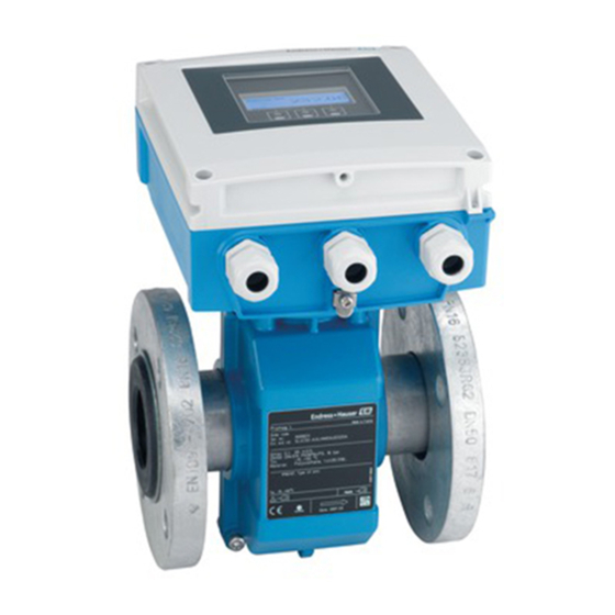
Page 8: Product Description
Product description Proline Promag L 400 Product description Product design A0017218 1 Important components of the compact version Display module Smart sensor electronics module HistoROM DAT (plug-in memory) Endress+Hauser... -
Page 9: Incoming Acceptance And Product Identification
Proline Promag L 400 Incoming acceptance and product identification Main electronics module Terminals (screw terminals, some available as plug-in terminals) Transmitter housing, compact version Cable glands Sensor, compact version Incoming acceptance and product identification Incoming acceptance Are the order codes on the... -
Page 10: Product Identification
Incoming acceptance and product identification Proline Promag L 400 • If one of the conditions is not satisfied, contact your Endress+Hauser Sales Center. • Depending on the device version, the CD-ROM might not be part of the delivery! In such cases, the technical documentation is available via the Internet or via the Endress +Hauser Operations App, see the "Device documentation"... -
Page 11: Storage And Transport
Enter the serial number (Ser. no.) of the device: see nameplate (→ 2, 10). All the associated documentation is displayed. Endress+Hauser Operations App The Endress+Hauser Operations App is available for Android (Google play) and iOS (App Store). Via the serial number: Launch the Endress+Hauser Operations App. -
Page 12: Transporting The Product
Storage and transport Proline Promag L 400 Transporting the product 5.2.1 For measuring devices ≤ DN 300 (12") WARNING Center of gravity of the measuring device is higher than the suspension points of the webbing slings. Risk of injury if the measuring device slips. -
Page 13: Mounting
Proline Promag L 400 Mounting A0016257 Mounting Installation conditions 6.1.1 Mounting position Mounting location A0023343 h ≥ 2 × DN Installation in down pipes Install a siphon with a vent valve downstream of the sensor in down pipes whose length h ≥... - Page 14 Mounting Proline Promag L 400 A0017064 3 Installation in a down pipe Vent valve Pipe siphon Length of down pipe Installation in partially filled pipes A partially filled pipe with a gradient necessitates a drain-type configuration. The empty pipe detection (EPD) function offers additional protection by detecting empty or partially filled pipes.
- Page 15 Proline Promag L 400 Mounting Orientation The direction of the arrow on the sensor nameplate helps you to install the sensor according to the flow direction. An optimum orientation position helps avoid gas and air accumulations and deposits in the measuring tube.
- Page 16 • Avoid direct exposure to weather conditions. • Protect the display against impact. • Protect the display from abrasion by sand in desert areas. A display protector can be ordered from Endress+Hauser: "Accessories" section System pressure A0015594 Furthermore, install pulse dampers if reciprocating, diaphragm or peristaltic pumps are used.
- Page 17 Proline Promag L 400 Mounting Vibrations It is recommended to mount the sensor and transmitter separately. A0016266 4 Measures to avoid device vibrations (L > 10 m (33 ft)) Adapters [mbar] 8 m/s 7 m/s 6 m/s 5 m/s 4 m/s max.
-
Page 18: Mounting The Measuring Device
Mounting Proline Promag L 400 6.1.3 Special mounting instructions Display protection ‣ To ensure that the optional display protection can be easily opened, maintain the following minimum head clearance: 350 mm (13.8 in) Mounting the measuring device 6.2.1 Required tools For transmitter •... - Page 19 Proline Promag L 400 Mounting If using ground disks, comply with the Installation Instructions provided. Observe required screw tightening torques (→ 19). Install the measuring device or turn the transmitter housing so that the cable entries do not point upwards.
- Page 20 Mounting Proline Promag L 400 Wall mounting 17 (0.67) 14 (0.55) 5.8 (0.23) 5.8 (0.23) 149 (5.85) A0020523 5 Engineering unit mm (in) Post mounting WARNING Excessive tightening torque applied to the fixing screws on plastic housing! Risk of damaging the plastic transmitter.
- Page 21 Proline Promag L 400 Mounting ø 20…70 TX 25 ø ( 0.79…2.75) SW 8 A0020705 6 Engineering unit mm (in) 6.2.5 Turning the transmitter housing TX 20 A0021602 Endress+Hauser...
- Page 22 Mounting Proline Promag L 400 3 mm A0021603 TX 20 A0021604 4 mm A0021605 Endress+Hauser...
- Page 23 Proline Promag L 400 Mounting Reassembling the transmitter housing WARNING Excessive tightening torque applied to the fixing screws! Damage to the transmitter. ‣ When reassembling, tighten the fixing screws as per the tightening torque: Step Fixing screw Tightening torques for housing made of:...
-
Page 24: Post-Installation Check
Electrical connection Proline Promag L 400 Reassembling the transmitter housing WARNING Excessive tightening torque applied to the fixing screws! Damage to the transmitter. ‣ When reassembling, tighten the fixing screws as per the tightening torque: Step Fixing screw Tightening torque for housing made of:... -
Page 25: Connection Conditions
Proline Promag L 400 Electrical connection Connection conditions 7.1.1 Required tools • Torque wrench • For cable entries: Use corresponding tools • For housing cover: Torx screwdriver or flat-blade screwdriver • Wire stripper • When using stranded cables: crimping tool for ferrule 7.1.2... - Page 26 Electrical connection Proline Promag L 400 Signal damping Max. 9 dB over the entire length of the cable cross-section Shielding Copper braided shielding or braided shielding with foil shield. When grounding the cable shield, observe the grounding concept of the plant.
- Page 27 Proline Promag L 400 Electrical connection Cable diameter • Cable glands supplied: – For standard cable: M20 × 1.5 with cable 6 to 12 mm (0.24 to 0.47 in) – For reinforced cable: M20 × 1.5 with cable 9.5 to 16 mm (0.37 to 0.63 in) •...
- Page 28 Electrical connection Proline Promag L 400 Remote version 6 5 7 8 4 37 36 42 41 n.c. n.c. n.c. 5 7 4 37 42 41 A0020534 7 Remote version terminal assignment Transmitter wall-mount housing Sensor connection housing Electrode cable Coil current cable n.c.
- Page 29 Proline Promag L 400 Electrical connection EtherNet/IP Device plug for signal transmission (device side) Assignment Coding Plug/socket Socket A0016812 7.1.5 Preparing the measuring device Remove dummy plug if present. If measuring device is delivered with cable glands: Observe cable specification (→ 25).
- Page 30 Electrical connection Proline Promag L 400 7.1.6 Preparing the connecting cable for the remote version When terminating the connecting cable, pay attention to the following points: • In the case of electrode cables, make sure that the ferrules do not touch the core shields on the sensor side.
-
Page 31: Connecting The Measuring Device
Proline Promag L 400 Electrical connection Sensor Electrode cable Coil current cable 20 (0.79)* 20 (0.79)* 160 (6.30)* 170 (6.69)* 80 (3.15) 70 (2.76) 50 (1.97) 50 (1.97) 18.5 (0.73) 10 (0.39) 6 (0.24) 8 (0.31) ³1 (0.04) A0016489 A0016488... - Page 32 Electrical connection Proline Promag L 400 WARNING Housing degree of protection may be voided due to insufficient sealing of the housing. ‣ Screw in the screw without using any lubricant. The threads on the cover are coated with a dry lubricant.
- Page 33 Proline Promag L 400 Electrical connection Connecting the supply voltage and PROFIBUS DP PH 2 2627 10 (0.4) A0023164 ‣ Connect the cable in accordance with the terminal assignment (→ 27). For supply voltage: open the shock protection cover.
- Page 34 Electrical connection Proline Promag L 400 Connecting the supply voltage and EtherNet/IP PH 2 10 (0.4) A0021356 ‣ Connect the cable in accordance with the terminal assignment (→ 27). For supply voltage: open the shock protection cover. 7.2.2 Connecting the remote version...
- Page 35 Proline Promag L 400 Electrical connection TX 20 6 5 7 8 4 37 36 42 41 A0017445 10 Transmitter: main electronics module with terminals 42 41 A0021527 11 Sensor: connection module 7.2.3 Ensuring potential equalization CAUTION Electrode damage can result in the complete failure of the device! ‣...
- Page 36 Electrical connection Proline Promag L 400 Connection examples for standard situations Metal, grounded pipe A0016315 12 Potential equalization via measuring tube Connection example in special situations Unlined and ungrounded metal pipe This connection method also applies in situations where: •...
- Page 37 Proline Promag L 400 Electrical connection Ground cable Copper wire, at least6 mm (0.0093 in A0016318 14 Potential equalization via ground terminal and ground disks For remote device versions, the ground terminal in the example always refers to the sensor and not to the transmitter.
-
Page 38: Hardware Settings
Electrical connection Proline Promag L 400 Hardware settings 7.3.1 Setting the device address EtherNet/IP The IP address of the measuring device can be configured for the network via DIP switches. Addressing data IP address and configuration options 1st octet 2nd octet... - Page 39 Proline Promag L 400 Electrical connection PROFIBUS DP The address must always be configured for a PROFIBUS DP/PA device. The valid address range is between 1 and 126. In a PROFIBUS DP/PA network, each address can only be assigned once. If an address is not configured correctly, the device is not recognized by the master.
-
Page 40: Ensuring The Degree Of Protection
Electrical connection Proline Promag L 400 DIP 1 DIP 3 390 Ω 220 Ω 390 Ω DIP 2 A0023063 16 Termination using DIP switches on the I/O electronics module (for baud rates < 1.5 MBaud) Ensuring the degree of protection 7.4.1... -
Page 41: Operation Options
Proline Promag L 400 Operation options Do the cables have adequate strain relief? Are all the cable glands installed, firmly tightened and leak-tight? Cable run with "water trap" (→ 40) ? Only for remote version: is the sensor connected to the right transmitter? ... - Page 42 Operation options Proline Promag L 400 8.1.2 Operating philosophy The individual parts of the operating menu are assigned to certain user roles. Each user role corresponds to typical tasks within the device lifecycle. For detailed information about the operating philosophy of the device, see the Operating Instructions for the device (→...
-
Page 43: Access To The Operating Menu Via The Local Display
Proline Promag L 400 Operation options Access to the operating menu via the local display X X X X X X 19.184 mA 12.5 X X X X X X Language à 20.50 English Deutsch Español Français User ABC_ DEFG... - Page 44 Operation options Proline Promag L 400 8.2.1 Operational display Status area Status signals Failure Function check Out of specification Maintenance required Diagnostic behavior Locking Communication Alarm Warning Device locked Remote operation enabled Display area Measured variables Symbol Meaning Volume flow...
- Page 45 Proline Promag L 400 Operation options 8.2.2 Navigation view Status area The following appears in the status area of the navigation view in the top right corner: • Of the submenu – The direct access code for the parameter you are navigating to (e.g. 0022-1) –...
- Page 46 Operation options Proline Promag L 400 Correction symbols under Clears all entered characters. Moves the input position Moves the input position Deletes one character one position to the left. one position to the right. immediately to the left of the input position.
- Page 47 Proline Promag L 400 Operation options Meaning Escape key combination (press keys simultaneously) In a menu, submenu • Pressing the key briefly: – Exits the current menu level and takes you to the next higher level. – If help text is open, closes the help text of the parameter.
- Page 48 Operation options Proline Promag L 400 8.2.6 User roles and related access authorization The two user roles "Operator" and "Maintenance" have different write access to the parameters if the customer defines a user-specific access code. This protects the device configuration via the local display from unauthorized access (→...
-
Page 49: Access To The Operating Menu Via The Web Browser
Proline Promag L 400 Operation options Switching on the keypad lock The keypad lock is switched on automatically: • Each time the device is restarted. • If the device has not been operated for longer than one minute in the measured value display. - Page 50 Operation options Proline Promag L 400 ON OFF Default Ethernet network settings IP 192.168.1.212 Write protection A0023353 • Once the DIP switch has been activated, the device must be restarted before the device uses the standard IP address. • If the standard IP address (top DIP switch No. 2 = ON) is used, there is no connection to the EtherNet/IP network.
- Page 51 Proline Promag L 400 Operation options Starting the Web browser Enter the IP address of the Web server in the address line of the Web browser: 192.168.1.212 If the IP address of the measuring device is known, enter the defined device address in the address line of the Web browser.
- Page 52 Operation options Proline Promag L 400 8.3.5 User interface A0017757-EN Picture of device Function row with 6 functions Device tag Header Working area Navigation area Header The following information appears in the header: • Device tag (→ 55) • Device status with status signal •...
-
Page 53: Access To The Operating Menu Via The Operating Tool
Proline Promag L 400 System integration Access to the operating menu via the operating tool For detailed information about access to the operating menu via operating tool, refer to the Operating Instructions for the device (→ 10). System integration For information on system integration, see the Operating Instructions for the device (→... -
Page 54: Setting The Operating Language
Commissioning Proline Promag L 400 • If hardware addressing is active, software addressing is disabled. • If a switch is made to hardware addressing, the address configured via software addressing is retained for the first 9 places (the first three octets). -
Page 55: Configuring The Measuring Device
Proline Promag L 400 Commissioning 10.5 Configuring the measuring device The Setup menu and its guided wizards enable fast commissioning of the measuring device. The wizards systematically guide the user through all the parameters required for configuration, such as parameters for measurement or outputs. - Page 56 Commissioning Proline Promag L 400 Navigation "Setup" menu → Advanced setup → Administration → Def. access code Structure of the submenu Define access code → Define access code Confirm access code Defining the access code via local display Navigate to the Enter access code parameter.
- Page 57 Proline Promag L 400 Commissioning The parameter values are now read only and cannot be edited any more (exception "Contrast display" parameter): • Via local display • Via service interface (CDI-RJ45) • Via HART protocol For device version with HART communication type...
-
Page 58: Diagnostic Information
Diagnostic information Proline Promag L 400 ON OFF Default Ethernet network settings IP 192.168.1.212 Write protection A0023059 Loosen the 4 fixing screws on the housing cover and open the housing cover. Setting the write protection switch (WP) on the main electronics module to the ON position enables the hardware write protection. - Page 59 Proline Promag L 400 Diagnostic information X X X X X X X X X X X X X X 20.50 S801 Supply voltage Menu Diagnostic list Diagnostics 1 S801 Supply voltage Diagnostics 2 Diagnostics 3 Supply voltage (ID:203) S801 0d00h02m25s...
- Page 60 www.addresses.endress.com...