Table of Contents
Advertisement
Quick Links
Advertisement
Table of Contents

Related Manuals for Endress+Hauser Float Tank Gauge LT11


Summary of Contents for Endress+Hauser Float Tank Gauge LT11
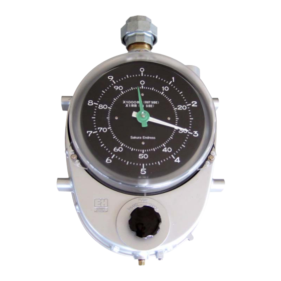
- Page 1 Operating Instructions Float Tank Gauge LT11/LT12 BA00404G/08/EN/02.12 71183255...
-
Page 2: Table Of Contents
Float Tank Gauge LT11/12 Table of Contents Table of Contents Safety instructions ......3 Display . -
Page 3: Safety Instructions
Safety instructions Designated use The Float Tank Gauge LT11/12 have been developed for use in all areas of industry. Many years of operation in wide variety of applications have proven their reliability. No electrical power is required to perform the mea- surement. -
Page 4: Notes On Safety Conventions And Symbols
Float Tank Gauge LT11/12 1 Safety instructions Notes on safety conventions and symbols In order to highlight safety-relevant or alternative operating procedures in the manual, the following conventions have been used, each indicated by a corresponding symbol in the margin. -
Page 5: Identification
Float Tank Gauge LT11/12 2 Identification Identification Device designation 2.1.1 Nameplate The following technical data are given on the instrument nameplate: Order cord Serial number Type Measuring range Tag number Endress+Hauser... -
Page 6: Product Structure
Float Tank Gauge LT11/12 2 Identification Product structure 2.2.1 LT11 (Threaded type, Low pressure) Display: Dial 2 pointers Numeric (mechanical counter) Dial 2 pointers , up side down Special version, TSP-no. to be spec Crank Unit: Not selected Selected Function: Basic version Special version, TSP-no. - Page 7 Float Tank Gauge LT11/12 2 Identification Float: 4.2 ㎏ , d = 400mm, 5.0 ㎏ , d = 400mm 8.0 ㎏ , d = 400mm Not selected 2.1 ㎏ , d = 140mm 2.4 ㎏ , d = 140mm Special version, TSP-no. to be spec.
- Page 8 Float Tank Gauge LT11/12 2 Identification 2.2.2 LT12 (Flange type, Low pressure) Display: Dial 2 pointers Numeric (mechanical counter) Dial 2 pointers , up side down Special version, TSP-no. to be spec. Crank Unit: Not selected Selected Function: Basic version Special version, TSP-no.
- Page 9 Float Tank Gauge LT11/12 2 Identification Float: 4.2 ㎏ , d = 400mm 5.0 ㎏ , d = 400mm 8.0 ㎏ , d = 400mm Not selected Special version, TSP-no. to be spec. Additional Option; Colour: Basic version C Copper free...
-
Page 10: Scope Of Delivery
Float Tank Gauge LT11/12 2 Identification Scope of delivery Following products is delivered as standard items. Item Unit Item Unit Gauge head Guide wire* Measuring tape Anchor hook* Float union (option) 90 Sheave elbow* Seal tape* Top anchor* Plug screw (only check... -
Page 11: Installation
Float Tank Gauge LT11/12 3 Installation Installation Incoming acceptance, transport, storage 3.1.1 Incoming acceptance Check the packing and contents for any signs damage. Check the shipment, make sure nothing is missing and that the scope of supply matches your order. -
Page 12: Lt11/12 Installation Tool
Float Tank Gauge LT11/12 3 Installation LT11/12 Installation tool When installing LT11/12, please prepare the following tools. :Use on tank top :Use at ground level :Use at both location Recommended tool for the installation :Not in use Tool Usage 13mm : Sheave elbow lid removal & reinstall... -
Page 13: Welding For Gauge Supporter And Pipe Supporter
Float Tank Gauge LT11/12 3 Installation Welding for Gauge supporter and pipe supporter When weld Gauge supporter and pipe supporter, please refer to the below drawing. Mounting center of gauge head & Guide pipe Center of Gauge supporter Guide Pipe 3.5.1... -
Page 14: Top Anchor, Hook & Base Plate Set Up Location
Float Tank Gauge LT11/12 3 Installation 3.5.2 Guide Pipe connection • Make sure to remove all the welding or cut off particles inside of the pipe. • Use activated sealing, in order to maintain the airtight state in the locations such as flange connection points. - Page 15 Float Tank Gauge LT11/12 3 Installation LT11 (threaded connection) ±5 1-1/2B socket 1B socket Tank top Guide wire Anchor hook *In case of LT12, process connection uses a flange instead of a socket. Endress+Hauser...
-
Page 16: Installation Condition
Float Tank Gauge LT11/12 3 Installation Installation condition 3.7.1 Dimensions 3.7.1.1 LT11 (Low pressure threaded type) Process connection (threaded) Top anchor Top anchor/seal pot Gauge head Seal pot Sheave elbow (except socket type) (PVC) without Union Rp1-1/2 Rp1-1/2 Rp1-1/2 10K 40A FF JIS... - Page 17 Float Tank Gauge LT11/12 3 Installation 3.7.1.2 LT12 (low pressure flange type) Gauge supporter Guage head U type Seal pot Top anchor Top anchor Top Anchor (PVC) ADC6 SUS316 90° sheave elbow 1-1/2 flange U type Seal pot (PVC) Anchor hook...
-
Page 18: Installation Reference Drawing And Kit Code
Float Tank Gauge LT11/12 3 Installation Installation reference drawing and Kit code 3.8.1 Coneroof tank (CRT) sheave elbow In LT12, Gauge head, Sheave elbow and Top ancher are connected with flange. *Please refer to 17 page "Process connection" list. Washer... - Page 19 Float Tank Gauge LT11/12 3 Installation 3.8.2 Tank top mount [Undergraund tank] In LT11, gauge head, Sheave elbow, seal pot and top anchor are connected with threaded. *Please refer to 17 page "Process con- nection" list. Washer Bolt Guide wire...
- Page 20 Float Tank Gauge LT11/12 3 Installation 3.8.3 Cone roof Tank with seal pot for CRT (LT12 type) In LT11, gauge head, Sheave elbow, sheave elbow seal pot and top anchor are connected with threaded. *Please refer to 17 page "Process con- nection"...
- Page 21 Float Tank Gauge LT11/12 3 Installation 3.8.4 Cone roof Tank with seal pot PVC for CRT (LT12 type) In LT11, gauge head, 90° Sheave elbow is connected with threaded, sheave elbow seal pot and top anchor are connected with flange.
- Page 22 Float Tank Gauge LT11/12 3 Installation 3.8.5 Compact cone roof Tank, guide pipe method (LT11) sheave elbow *Please refer to 17 page "Process connection" list. Note! When hoisting and lowering the float using crank unit , please slowly hoist and lower the float not to stick the guide pipe.
- Page 23 Float Tank Gauge LT11/12 3 Installation 3.8.6 Tank top mount, guide pipe method (LT11) *Please refer to 17 page "Process connection" list. Note! When hoisting and lowering the float using crank unit , please slowly hoist and lower the float not to stick the guide pipe Ø...
- Page 24 Float Tank Gauge LT11/12 3 Installation 3.8.7 Gas holder (LT11) In LT12, guide head and 90°Sheave sheave elbow elbow are connected with flange. *Please refer to 17 page "Process con- nection" list. Applocation (060) LT11 LT12 Application Item Material/Quantity Material/Quantity...
- Page 25 Float Tank Gauge LT11/12 3 Installation 3.8.8 Floating roof Tank [FRT](LT11) In LT12, Sheave elbow are connected with flange. sheave elbow *Please refer to 17 page "Process con- nection" list. Applocation (060) LT11 LT12 Application Item Material/Quantity Material/Quantity Guage head...
-
Page 26: Guide Wire Installation
Float Tank Gauge LT11/12 3 Installation Guide wire installation Note! • Be careful not to bend the guide wire • Two guide wires should be arranged parallel to each other and perpendicular to the tank floor. • Since it is extremely difficult to repair the guide wire and guide hook in the bottom of the tank, please make sure to check the strength of those equipment thoroughly before filling the tank with the fluid. -
Page 27: Measuring Tape And Measuring Wire Installation
Float Tank Gauge LT11/12 3 Installation 3.10 Measuring tape and measuring wire installation 1)Extend measuring wire while folding back a length of 1.5 m wire not to twist. 2)Before you start this process, open the covers of Sheave elbow and gauge head. - Page 28 Float Tank Gauge LT11/12 3 Installation 3.10.1 Cone-roof tank 1) First, insert the measuring tape (the end that does not have a small hole) into the tank from the Sheave elbow directly above the tank. Meanwhile, the other end of the measuring tape (the ring shaped side with a small hole) needs to go through the Sheave elbow just above the gauge head, and send it into the gauge head.
- Page 29 Float Tank Gauge LT11/12 3 Installation Connection with Measuring tape and float Endress+Hauser...
- Page 30 Float Tank Gauge LT11/12 3 Installation Floating-roof tank 1) Pass one end of the measuring wire into the tank through the 90° sheave elbow (Located right above the gauge head) and that right above the tank. 2) Inside the tank, connect the measuring tape to the float in the manner. Again on the tank top, connect the measuring wire to the measuring tape and feed the measuring tape into the gauge head.
- Page 31 Float Tank Gauge LT11/12 3 Installation 3.10.2 Internal adjustment Tape guide 1) Again in the gauge head, turn the tape drum in the direction indicated by arrow in the bellow fig. to tense the measuring tape. Measuring tape Tape guide...
- Page 32 Float Tank Gauge LT11/12 3 Installation 3.10.3 Setting conster drum The conster drum should be set after the measuring tape has been stretched in position. Caution! When winding the conster spring motor from the large drum to the small drum, do not remove your hand from the large drum until the spring is completely wound.
-
Page 33: Display
Float Tank Gauge LT11/12 4 Display Display Dial display Pointer setting and how to scale readout When calibrating (pointer setting) to authorized value as calculated value or measured value, there are differences between Dial display type and Counter display type. Usually, if tank height is up to 20mm, indicator is Dial display and if tank height is over 20mm, indicator is counter display. -
Page 34: Counter Display
Float Tank Gauge LT11/12 4 Display Counter display After removing the cover from the indicator of the gauge head, loosen a screw of the center on a scale plate in order to be rotated the scale plate freely. The counter drum changes one position a numeral of the first drum every rotations (100 mm) of the scale plate. -
Page 35: Indicating Adjustment
Float Tank Gauge LT11/12 4 Display Indicating adjustment Calibration method 1) Put actual measuring liquid into tank and calibrate to the measuring value 2) When tank is empty, calibrate through calculation 3) Put water into tank and calibrate to the measuring value After removing the cover from the indicator of the gauge head, loosen the cap nut. - Page 36 Float Tank Gauge LT11/12 4 Display Ø400 float Calculating formula Lf :When a float start to float, level height (mm) ρ:Gravity of actual liquit (g/cm 3 W :Float weight (g) Q :Half of float volume(cm 3 A :Cross-sectional area of float cylindrical part (cm )...
- Page 37 Float Tank Gauge LT11/12 4 Display Ø140 float Calculating formula Lf :When a float start to float, level height (mm) ρ:Gravity of actual liquit (g/cm 3 3 W :Float weight (g) Q :Half of float volume(cm A :Cross-sectional area of float cylindrical part (cm )...
- Page 38 Float Tank Gauge LT11/12 4 Display Cone-roof tank (with seal pot PVC) and Floating roof tank Calculating formula Lf :When a float start to float, level height (mm) ρ:Gravity of actual liquit (g/cm 3 W :Float weight (g) Q :Half of float volume(cm 3...
-
Page 39: Operation
Float Tank Gauge LT11/12 5 Operation Operation Check handle This is used in order to check that a gauge operates normally. Note! • When checking the gauge performance using Check handle, please do the check after putting a liquit into tank. -
Page 40: Maintenance
Float Tank Gauge LT11/12 6 Maintenance Maintenance Before you start the maintenance • Give special attention in handling flammable liquid. Give plenty of waiting time for the liquid to calm down after the loading, then start the maintenance (refer to thetable below). -
Page 41: Daily Checking
Float Tank Gauge LT11/12 6 Maintenance Daily checking The level gauge does not require any operation after it has been properly mounted on a tank. Periodical checking Follow the Table below to do the periodical inspection. Periodical inspection Procedures Check Item... -
Page 42: Troubleshooting
Float Tank Gauge LT11/12 7 Troubleshooting Troubleshooting Failure cause and Countermeasure Symptom Possible cause Corrective Measure Indication does not 1) Measuring tape broken After opening the tank, replace assuring change at all tape. 2) Guide wire caught After opening the tank, re-stretch guide wire. -
Page 43: Spare Parts
7 Troubleshooting Spare parts Spare parts are contained in kits. Spare parts which you can order from Endress+Hauser for the Promonitor are shown with their order numbers in the diagram below. For more information on service and spare parts, contact Endress+Hauser. - Page 44 Float Tank Gauge LT11/12 7 Troubleshooting Specification Specification 017860-5221 Steel front cover assembly 52015582 Conster spring, 5m 017860-5220 Cover counter LT1120/LT1220 017860-5033 Conster spring, 10m Conster tape drum Cover 017860-5450 Front cover, plastic 017860-5035 Conster spring, 20m (range 16m, 20m)
- Page 45 Float Tank Gauge LT11/12 7 Troubleshooting 7.2.2 Sheave elbow Specification Specification 017860-0709 O-ring bearing P8 017860-1259 SS304 bearing Sheave O-ring elbow bearing 70106015 Packing, albow, low pressure, Cork 017860-0018 Sheave elbow / alu/ ANSI316 roller 150# Packing Sheave 017860-0704 SS316L roller...
- Page 46 Float Tank Gauge LT11/12 7 Troubleshooting 7.2.3 Float and Measuring tape Universal joint Ø400 Specification Specification 017860-7003 Float LF400 316 5kg 017860-0007 Measuring tape, FRT 10m 1.6mm 316 Float 017860-7010 Float LF400 316 8kg 017860-0008 Measuring tape, FRT 10m 1.6mm 316...
- Page 47 Float Tank Gauge LT11/12 7 Troubleshooting 7.2.4 Top anchor (Low/ middle / high pressure) Specification Specification 70106010 Packing, T-anchor, thread , Cork 017860-0030 Housing Alu, 1" threaded Packing Top anchor T-anchor housing low pressure 017860-0058 Top anchor, SUSI316 Weld-fixing 017860-0808...
- Page 48 Float Tank Gauge LT11/12 7 Troubleshooting 7.2.5 Seal pot, measuring wire and guide wire S e a S e a L i q u L i q u Endress+Hauser...
- Page 49 Float Tank Gauge LT11/12 7 Troubleshooting Specification Specification 70106015 Packing, elbow, low pressure, Cork 017860-5441 Bottom anchor, SS400, bolt, nut steel Packing O-ring 71134090 Seal pot, elbow roller, PVC 017860-5442 Bottom anchor, 316, bolt, nut steel Sheave Anchor elbow roller...
-
Page 50: Technical Data
Float Tank Gauge LT11/12 Technical data Technical data at a glance Product root Measuring range/Specification Measuring range LT11/LT12 0 - 2.5, 5, 10, 16, 20, 30m LT11/LT12 ±2mm (Under the condition of; specific gravity: 1g/cm ,measuring range; 10m) Accuracy LT11Application (060)...005,008 ±30mm (Under the condition of;... - Page 51 Erklärung zur Kontamination und Reinigung Please reference the Return Authorization Number (RA#), obtained from Endress+Hauser, on all paperwork and mark the RA# clearly on the outside of the box. If this procedure is not followed, it may result in the refusal of the package at our facility.
- Page 52 WWW.endress.com/worldwide Endress + Hauser Yamanashi Co., Ltd. 862-1 Mitsukunugi Sakaigawa-cho Fuefuki-shi Yamanashi, 406-0846 Japan Phone: ++81 55 266 4964 Fax: ++81 55 266 4969 BA00404G/08/EN/02.12 71183255 FM+SGML 8.0J...