Table of Contents
Advertisement
Quick Links
Advertisement
Chapters
Table of Contents

Related Manuals for Endress+Hauser LT1100


Summary of Contents for Endress+Hauser LT1100
- Page 1 Operating Instructions Float Tank Gauge LT1100/1200 BA1002N/08/en/05.08 70105556...
-
Page 2: Table Of Contents
Float Tank Gauge LT1100/1200 Table of Contents Table of Contents Safety instructions ....3 Display ......34 Designated use . -
Page 3: Safety Instructions
Safety instructions Designated use The Float Tank Gauge LT1100/1200 have been developed for use in all areas of industry. Many years of operation in wide variety of applications have proven their reliability. No electrical power is required to perform the measurement. -
Page 4: Notes On Safety Conventions And Symbols
Float Tank Gauge LT1100/1200 1 Safety instructions Notes on safety conventions and symbols In order to highlight safety-relevant or alternative operating procedures in the manual, the following conventions have been used, each indicated by a corresponding symbol in the margin. -
Page 5: Identification
Float Tank Gauge LT1100/1200 2 Identification Identification Device designation 2.1.1 Nameplate The following technical data are given on the instrument nameplate: Type cord Measuring range Serial number Fig 1: LT1100/1200 nameplate Endress+Hauser... -
Page 6: Product Structure
Float Tank Gauge LT1100/1200 2 Identification Product structure 2.2.1 LT1100 (LT11) Display: Dial 2 pointers Numeric (mechanical counter) Dial 2 pointers, up side down Special version Crank Unit: Not selected used Special version Function: Basic version Special version Process Connection: 0 PS1-1/2”, w/o union nut... - Page 7 Float Tank Gauge LT1100/1200 2 Identification Float: 4.2 ㎏ , d = 400mm, lid. density 0.5≤ρ≤0.65 5.0 ㎏ , d = 400mm, lid. density 0.65≤ρ≤1.05 8.0 ㎏ , d = 400mm, lid. density 1.05≤ρ≤2.00 Not selected 2.1 ㎏ , d = 140mm, lid. density 0.5≤ρ≤0.94 2.4 ㎏...
- Page 8 Float Tank Gauge LT1100/1200 2 Identification 2.2.2 LT1200 (LT12) Display: Dial 2 pointers Numeric (mechanical counter) Dial 2 pointers, up side down Special version Crank Unit: Not selected Integrated in gauge head Special version Function: Basic version Special version Process Connection: 1 flange JIS 10K 40A RF 2 flange ANSI 1-1/2”...
- Page 9 Float Tank Gauge LT1100/1200 2 Identification Float: 4.2 ㎏ , d = 400mm, lid. density 0.5≤ρ≤0.65 5.0 ㎏ , d = 400mm, lid. density 0.65≤ρ≤1.05 8.0 ㎏ , d = 400mm, lid. density 1.05≤ρ≤2.00 Not selected Special version Additional Option; Color: Basic version;...
-
Page 10: Scope Of Delivery
Float Tank Gauge LT1100/1200 2 Identification Scope of delivery Following products is delivered as standard items. Item Unit Item Unit Gauge head Guide wire* Measuring tape Wire hook* Float union (option) 90 guide elbow* Seal tape* Top anchor* Plug screw (only check... -
Page 11: Supplied Documentation
EN 50014 “Electrical apparatus for potentially explosive atmospheres-General requirements”. The instrument described in this manual thus complies with the statutory requirements of the EG directives. Endress+Hauser confirms the suc- cessful testing of the instrument by affixing to it the CE mark. -
Page 12: Installation
Float Tank Gauge LT1100/1200 3 Installation Installation Incoming acceptance, transport, storage 3.1.1 Incoming acceptance Check the packing and contents for any signs damage. Check the shipment, make sure nothing is missing and that the scope of supply matches your order. -
Page 13: Installation Tool
Float Tank Gauge LT1100/1200 3 Installation Installation tool When installing LT1100/1200, please prepare the following tools. :Use on tank top :Use at ground level :Use at both location Recommended tool for the installation :Not in use Tool Usage 13mm : Guide elbow lid removal & reinstall... -
Page 14: Welding For Gauge Supporter And Pipe Supporter
Float Tank Gauge LT1100/1200 3 Installation Welding for Gauge supporter and pipe supporter When weld Gauge supporter and pipe supporter, please refer to the below drawing. Mounting center of gauge head & Guide pipe Center of Gauge supporter Guide Pipe 3.5.1... -
Page 15: Top Anchor, Hook & Base Plate Set Up Location
Chamfering burr Top anchor, hook & base plate set up location LT1200 (flange connection) Nozzle flange for Gauge head Nozzle flange for Top anchor Tank top *In case of LT1100, process connection uses a socket instead of a flange. Endress+Hauser... - Page 16 Float Tank Gauge LT1100/1200 3 Installation LT1100 (threaded connection) ±5 1 1/2B socket 1B socket Tank top Guide wire Wire hook *In case of LT1200, process connection uses a flange instead of a socket. Endress+Hauser...
-
Page 17: Installation Condition
Float Tank Gauge LT1100/1200 3 Installation Installation condition 3.7.1 Dimensions, 3.7.1.1 LT1100 (threaded type) Process connection for guide elbow and top anchor depends on specification of “Order information / process connection (gauge head)/ 040". But the threaded connection is as follows. When selecting the threaded PS, PT, G(PF), guide elbow is PS, top anchor is PT. -
Page 18: Gauge Supporter
Float Tank Gauge LT1100/1200 3 Installation 3.7.1.2 LT1200 (low pressure flange type) Gauge supporter Guage head U type Seal pot Top anchor Top anchor Top Anchor (PVC) ADC6 SUS316 90° Guide elbow 1 1/2" flange Wire hook U type Seal pot (PVC) (Except all-in-one type) 1 1/2"... -
Page 19: Installation Reference Drawing And Kit Code
Float Tank Gauge LT1100/1200 3 Installation Installation reference drawing and Kit code 3.8.1 Coneroof tank (CRT) In LT1200, Gauge head, Guide elbow and Top ancher are connected with flange. Process connection for guide elbow and top anchor depends on specification of "Order... -
Page 20: Guide Wire
Float Tank Gauge LT1100/1200 3 Installation 3.8.2 Tank top mount [Undergraund tank] In LT1200, guide head and top anchor are connected with flange. Process connection for top anchor depends on specification of "Order information / Process connection (gauge head) / 040". - Page 21 Float Tank Gauge LT1100/1200 3 Installation 3.8.3 Cone roof Tank with seal pot for CRT (LT1200 type) In LT1100, gauge head, guide elbow, seal pot and top anchor are connected with threaded. Process connection for guide elbow, seal pot and top anchor depends on specification of “Order information / process...
- Page 22 Float Tank Gauge LT1100/1200 3 Installation 3.8.4 Cone roof Tank with seal pot PVC for CRT (LT1200 type) In LT1100, gauge head, 90° guide elbow is connected with threaded, seal pot and top anchor are connected with flange. Process connection for guide...
- Page 23 Float Tank Gauge LT1100/1200 3 Installation 3.8.5 Compact cone roof Tank, guide pipe method max. 10m (LT1100) Process connection for guide elbow, depends on specification of "Order information / process connection (gauge head) / 040". But the threaded connection is as follows.
- Page 24 Float Tank Gauge LT1100/1200 3 Installation 3.8.6 Tank top mount, guide pipe method max. 10m (LT1100) Ø Applocation (060) LT1100 Max.10m/Guide pipe Application Item Material/Quantity Guage head Outer coating : ADC12 (inverted mounting)/1 Float Φ140 SUS316/1 Measuring tape SUS316/1 Endress+Hauser...
- Page 25 Float Tank Gauge LT1100/1200 3 Installation 3.8.7 Gas holder (LT1100) In LT1200, guide head and 90°guide elbow are connected with flange. Process connection for guide elbow depends on specifica- tion of “Order information / process connection (gauge head) / 040".
- Page 26 Float Tank Gauge LT1100/1200 3 Installation 3.8.8 Floating roof Tank [FRT] (LT1100) In LT1200, guide elbow are connected with flange. Process connection for guide elbow depends on specification of "Order information / process connection (gauge head) / 040". But the threaded connection is as follows.
-
Page 27: Installation
Float Tank Gauge LT1100/1200 3 Installation Installation 3.9.1 Guide wire installation Note! • Be careful not to bend the guide wire • Two guide wires should be arranged parallel to each other and perpendicular to the tank floor. • Since it is extremely difficult to repair the guide wire and guide hook in the bottom of the tank, please make sure to check the strength of those equipment thoroughly before filling the tank with the fluid. - Page 28 Float Tank Gauge LT1100/1200 3 Installation 3.9.2 1)Extend measuring wire while folding back a length of 1.5 m wire not to twist. 2)Before you start this process, open the covers of guide elbow and gauge head. Extend measuring wire while folding back a length of 1.5m...
- Page 29 Float Tank Gauge LT1100/1200 3 Installation 3.9.2.1 Cone-roof tank 1) First, insert the measuring tape (the end that does not have a small hole) into the tank from the guide elbow directly above the tank. Meanwhile, the other end of the measuring tape (the ring shaped side with a small hole) needs to go through the guide elbow just above the gauge head, and send it into the gauge head.
- Page 30 Float Tank Gauge LT1100/1200 3 Installation Connection with Measuring tape and float 2 Fold a measuring tape 3 Fole from the center of Fold a measuring tape at approx.65mm again foled measuring tape at approx. 65mm again 65m m 65m m...
- Page 31 Float Tank Gauge LT1100/1200 3 Installation 3.9.2.2 Floating-roof tank 1) Pass one end of the measuring wire into the tank through the 90° sheave elbow (Located right above the gauge head) and that right above the tank. 2) Inside the tank, connect the measuring tape to the float in the manner. Again on the tank top, connect the measuring wire to the measuring tape and feed the measuring tape into the gauge head.
- Page 32 Float Tank Gauge LT1100/1200 3 Installation 3.9.3 Internal adjustment Tape guide 1) Again in the gauge head, turn the tape drum in the direction indicated by arrow in the bellow fig. to tense the measuring tape. Measuring tape Tape guide...
- Page 33 Float Tank Gauge LT1100/1200 3 Installation 3.9.4 Setting conster drum The conster drum should be set after the measuring tape has been stretched in position. Caution! When winding the conster spring motor from the large drum to the small drum, do not remove your hand from the large drum until the spring is completely wound.
-
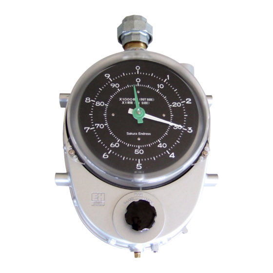
Page 34: Display
Float Tank Gauge LT1100/1200 4 Display Display Dial display Pointer setting and how to scale readout When calibrating (pointer setting) to authorized value as calculated value or measured value, there are differences between Dial display type and Counter display type. Usually, if tank height is up to 20mm, indicator is Dial display and if tank height is over 20mm, indicator is counter display. -
Page 35: Counter Display
Float Tank Gauge LT1100/1200 4 Display Counter display After removing the cover from the indicator of the gauge head, loosen a screw of the center on a scale plate in order to be rotated the scale plate freely. The counter drum changes one position a numeral of the first drum every rotations (100 mm) of the scale plate. -
Page 36: Indicating Adjustment
Float Tank Gauge LT1100/1200 4 Display Indicating adjustment Calibration method 1) Put actual measuring liquid into tank and calibrate to the measuring value 2) When tank is empty, calibrate through calculation 3) Put water into tank and calibrate to the measuring value After removing the cover from the indicator of the gauge head, loosen the cap nut. - Page 37 Float Tank Gauge LT1100/1200 4 Display Ø400 float Calculating formula Lf :When a float start to float, level height (mm) ρ:Gravity of actual liquit (g/cm 3 W :Float weight (g) Q :Half of float volume(cm 3 A :Cross-sectional area of float cylindrical part (cm )...
- Page 38 Float Tank Gauge LT1100/1200 4 Display Ø140 float Calculating formula Lf :When a float start to float, level height (mm) ρ:Gravity of actual liquit (g/cm 3 3 W :Float weight (g) Q :Half of float volume(cm A :Cross-sectional area of float cylindrical part (cm )...
- Page 39 Float Tank Gauge LT1100/1200 4 Display Cone-roof tank (with seal pot PVC) and Floating roof tank Calculating formula Lf :When a float start to float, level height (mm) ρ:Gravity of actual liquit (g/cm 3 W :Float weight (g) Q :Half of float volume(cm 3...
-
Page 40: Operation
Float Tank Gauge LT1100/1200 5 Operation Operation Check handle This is used in order to check that a gauge operates normally. Note! • When checking the gauge performance using Check handle, please do the check after putting a liquit into tank. -
Page 41: Maintenance
Float Tank Gauge LT1100/1200 6 Maintenance Maintenance Before you start the maintenance • Give special attention in handling flammable liquid. Give plenty of waiting time for the liquid to calm down after the loading, then start the maintenance (refer to thetable below). -
Page 42: Daily Checking
Float Tank Gauge LT1100/1200 6 Maintenance Daily checking The level gauge does not require any operation after it has been properly mounted on a tank. Periodical checking Follow the Table below to do the periodical inspection. Periodical inspection Procedures Check Item... -
Page 43: Troubleshooting
Float Tank Gauge LT1100/1200 7 Troubleshooting Troubleshooting Symptom Possible cause Corrective Measure Indication does not 1) Measuring tape broken After opening the tank, replace assuring change at all tape. 2) Guide wire caught After opening the tank, re-stretch guide wire. -
Page 44: Spare Parts And Drawing
Float Tank Gauge LT1100/1200 8 Spare parts and drawing Spare parts and drawing Gauge head 017860-5221 56004464 017860-5450 017860-5407 017860-5220 56004288 017860-0119 017860-5401 017860-5402 017860-5403 017860-5404 017860-5405 56004406 017860-0101 56004465 70106017(V6502) 017860-5440 017860-0220 017860-0221 70106005 017860-0222 017860-0213 017860-0223 56004503 017860-0224... - Page 45 Float Tank Gauge LT1100/1200 8 Spare parts and drawing Specification Specification 017860-5036 52016945 Conster spring, 30m Bearing for tape drum 017860-5123 56004503 Tape drum - standard Tape holder (package) 56004502 017860-0106 Tape holder (KAO Spec/package) Conster drum - large 017860-0107...
- Page 46 Float Tank Gauge LT1100/1200 8 Spare parts and drawing Float and Measuring tape 017860-5302 017860-5304 52017003 017860-5305 52017004 017860-5306 56004370 017860-0005 56004369 017860-0006 52017001 017860-5307 52017002 017860-0007 56004367 017860-0008 56004368 017860-5309 017860-0011 017860-0012 017860-5310 140φ 017860-0013 017860-0210 017860-0014 52004412 017860-0211 400φ...
- Page 47 Top anchor Alu+SUS316 shaft/ spring 017860-0025 Top anchor Alu + SUS316 shaft 150#, PT1" 1.5" LT1200 017860-0026 Top anchor SUS316 threaded 150#, 017860-0030 Housing Alu, 1" threaded, LT1100 1.5" LT1200 70106010 Packing, Top anchor, thread, V6502, 017860-0808 SS304 shaft (for LT-1100/1200)? low pressure Endress+Hauser...
- Page 48 Float Tank Gauge LT1100/1200 8 Spare parts and drawing Seal pot, measuring wire and guide wire 70106015 52017103 52017110 017860-5431 52017104 52017111 52017100 017860-5430 017860-5432 017860-0720 017860-5425 56004354 017860-5441 017860-5442 52016951 017860-5452 017860-5501 017860-5502 017860-5503 017860-0044 017860-5504 017860-5505 017860-0721 017860-0046...
- Page 49 Float Tank Gauge LT1100/1200 8 Spare parts and drawing Specification Specification 017860-5524 Guide wire, solid, SUS316, 20M 017860-5525 Guide wire, solid, 316, 30M 52017103 Seal pot (SGP/AC4A?PS1-1/2") 52017110 Seal pot SS316/SS316,PS1-1/2" 52017104 Seal pot SGP/AC4A,JIS10K 40A 52017111 Seal pot SS316/SS316,JIS10K 40A...
- Page 50 WWW.endress.com/worldwide Endress + Hauser Yamanashi Co., Ltd. 862-1 Mitsukunugi Sakaigawa-cho Fuefuki-shi Yamanashi, 406-0846 Japan Phone: ++81 55 266 4964 Fax: ++81 55 266 4969 BA1002N/08/en/05.08 70105556 FM+SGML 6.0...