Endress+Hauser Liquiphant FTL64 Brief Operating Instructions
Hide thumbs
Also See for Liquiphant FTL64:
- Operating instructions manual (64 pages) ,
- Technical information (52 pages) ,
- Brief operating instructions (29 pages)
Table of Contents
Advertisement
Quick Links
KA01480F/00/EN/02.22-00
71566288
2022-04-05
Products
Brief Operating Instructions
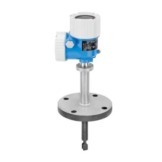
Liquiphant FTL64
Vibronic
Point level switch for liquids in high-temperature
applications
These Instructions are Brief Operating Instructions; they are
not a substitute for the Operating Instructions pertaining to
the device.
Detailed information about the device can be found in the
Operating Instructions and the other documentation:
Available for all device versions via:
• Internet:
www.endress.com/deviceviewer
• Smart phone/tablet: Endress+Hauser Operations App
Solutions
Services
Advertisement
Table of Contents

Related Manuals for Endress+Hauser Liquiphant FTL64


Summary of Contents for Endress+Hauser Liquiphant FTL64
- Page 1 Operating Instructions pertaining to the device. Detailed information about the device can be found in the Operating Instructions and the other documentation: Available for all device versions via: • Internet: www.endress.com/deviceviewer • Smart phone/tablet: Endress+Hauser Operations App...
-
Page 2: Associated Documentation
Associated documentation Liquiphant FTL64 Associated documentation Order code: XXXXX-XXXXXX Ser. no.: XXXXXXXXXXXX Ext. ord. cd.: XXX.XXXX.XX Serial number www.endress.com/deviceviewer Endress+Hauser Operations App A0023555 About this document Symbols 2.1.1 Safety symbols DANGER This symbol alerts you to a dangerous situation. Failure to avoid this situation will result in serious or fatal injury. - Page 3 Liquiphant FTL64 About this document This symbol alerts you to a dangerous situation. Failure to avoid this situation can result in serious or fatal injury. CAUTION This symbol alerts you to a dangerous situation. Failure to avoid this situation can result in minor or medium injury.
-
Page 4: Basic Safety Instructions
Basic safety instructions Liquiphant FTL64 Basic safety instructions Requirements for the personnel The personnel must fulfill the following requirements to carry out the necessary tasks, e. g., commissioning and maintenance: ‣ Trained, qualified specialists must have a relevant qualification for the specific function and task ‣... -
Page 5: Product Safety
It meets the general safety standards and legal requirements. It also complies with the EU directives listed in the device-specific EU Declaration of Conformity. Endress+Hauser confirms this by affixing the CE mark to the device. Incoming acceptance and product identification... -
Page 6: Product Identification
All of the information on the measuring device is displayed along with an overview of the scope of technical documentation provided. • Enter the serial number on the nameplate into the Endress+Hauser Operations app or scan the 2-D matrix code on the nameplate with the Endress+Hauser Operations app 4.2.1... -
Page 7: Mounting Requirements
Liquiphant FTL64 Mounting A0042329 1 Installation examples for a vessel, tank or pipe Vessel insulation (example with temperature spacer) If process temperatures are high, the device should be included in a vessel insulation system to prevent the electronics from heating as a result of thermal radiation or convection. - Page 8 Mounting Liquiphant FTL64 A0044069 2 Typical switch points. Unit of measurement mm (in) Installation from above Installation from below Installation from the side Switch point 5.1.2 Take viscosity into consideration Viscosity values • Low viscosity : < 2 000 mPa⋅s • High viscosity: > 2 000 to 10 000 mPa⋅s Low viscosity It is permitted to position the tuning fork within the installation socket.
- Page 9 Liquiphant FTL64 Mounting High viscosity NOTICE Highly viscous liquids may cause switching delays. ‣ Make sure that the liquid can run off the tuning fork easily. ‣ Deburr the socket surface. The tuning fork must be located outside the installation socket! >...
- Page 10 Mounting Liquiphant FTL64 5.1.4 Take clearance into consideration A0042340 6 Take clearance outside the tank into consideration 5.1.5 Support the device NOTICE If the device is supported incorrectly, shocks and vibrations can damage the coated surface. ‣ Only use suitable supports.
-
Page 11: Mounting The Device
Liquiphant FTL64 Mounting A0042356 7 Examples of support in the event of dynamic load Mounting the device 5.2.1 Required tool • Open-ended wrench for sensor installation • Allen key for housing locking screw 5.2.2 Installation Aligning the tuning fork using the marking Markings may include the following: •... - Page 12 Mounting Liquiphant FTL64 A0042348 8 Markings to align the tuning fork Installing in pipes • Flow velocity up to 5 m/s with a viscosity of 1 mPa⋅s and density of 1 g/cm (SGU). Check for correct functioning in the event of other process medium conditions.
- Page 13 Liquiphant FTL64 Mounting A0042423 10 Screwing in the device Aligning the cable entry 4 3.5 Nm A0042355 11 Housing with external locking screw and drip loop The locking screw is not tightened when the device is delivered. Loosen the external locking screw (maximum 1.5 turns).
-
Page 14: Electrical Connection
Electrical connection Liquiphant FTL64 Tighten the external locking screw. Electrical connection Required tool • Screwdriver for electrical connection • Allen key for screw of cover lock Connecting requirements 6.2.1 Cover with securing screw In the case of devices for use in the hazardous area with a certain type of protection, the cover is sealed by a securing screw. -
Page 15: Connecting The Device
Liquiphant FTL64 Electrical connection Connecting the device Housing thread The thread of the electronics and connection compartment is coated with lubricant varnish. Avoid additional lubrication. 6.3.1 2-wire AC (electronic insert FEL61) • Two-wire AC version • Switches the load directly into the power supply circuit via an electronic switch; always connect in series with a load •... - Page 16 Electrical connection Liquiphant FTL64 U 19...253 V AC I max: 350 mA >0,7 >0,5 L1 N A0036060 13 2-wire AC, electronic insert FEL61 Endress+Hauser...
- Page 17 Liquiphant FTL64 Electrical connection Behavior of switch output and signaling ΔU <3.8 mA ΔU <3.8 mA <3.8 mA A0031901 14 Behavior of switch output and signaling, electronic insert FEL61 MAX DIP switch for setting MAX safety mode MIN DIP switch for setting MIN safety mode...
- Page 18 Electrical connection Liquiphant FTL64 Selection tool for relays 207 230 253 A0042052 15 Recommended minimum holding power/rated power for load Holding power/rated power in [VA] Operating voltage in [V] AC mode • Operating voltage: 24 V, 50 Hz/60 Hz •...
- Page 19 Liquiphant FTL64 Electrical connection Supply voltage WARNING Failure to use the prescribed power unit. Risk of potentially life-threatening electric shock! ‣ The FEL62 may only be powered by devices with safe galvanic isolation, as per IEC 61010-1. U = 10 to 55 V Comply with the following according to IEC/EN61010-1: provide a suitable circuit breaker for the device and limit the current to 500 mA, e.g.
- Page 20 Electrical connection Liquiphant FTL64 Terminal assignment U = 10...55 V DC 350 mA I max: 350 mA 55 V >0,7 >0,5 0.5 A L+ L- A0036061 16 3-wire DC-PNP, electronic insert FEL62 Connection wiring with terminals Connection wiring with M12 plug in housing as per EN61131-2 standard...
- Page 21 Liquiphant FTL64 Electrical connection Behavior of switch output and signaling (L–) ΔU <100 µA (L–) (L–) ΔU <100 µA (L–) <100 µA (L–) A0033508 17 Behavior of switch output and signaling, electronic insert FEL62 MAX DIP switch for setting MAX safety mode...
- Page 22 Electrical connection Liquiphant FTL64 Supply voltage U = 19 to 253 V , 50 Hz/60 Hz / 19 to 55 V Comply with the following according to IEC/EN61010-1: provide a suitable circuit breaker for the device and limit the current to 500 mA, e.g. by installing a 0.5 A fuse (slow-blow) in the power supply circuit.
- Page 23 Liquiphant FTL64 Electrical connection Terminal assignment >0,7 U = 19...55 V DC >0,5 U 19...253 V AC 0.5 A A0036062 18 Universal current connection with relay output, electronic insert FEL64 When bridged, the relay output works with NPN logic...
-
Page 24: Power Consumption
Electrical connection Liquiphant FTL64 Behavior of switch output and signaling A0033513 19 Behavior of switch output and signaling, electronic insert FEL64 MAX DIP switch for setting MAX safety mode MIN DIP switch for setting MIN safety mode LED red for alarm... - Page 25 Liquiphant FTL64 Electrical connection Connectable load Loads switched via 2 potential-free changeover contacts (DPDT) • I ≤ 6 A (Ex de 4 A), U~ ≤ AC 253 V; P~ ≤ 1 500 VA, cos φ = 1, P~ ≤ 750 VA, cos φ > 0.7 • I ≤ 6 A (Ex de 4 A) to DC 30 V, I DC ≤...
- Page 26 Electrical connection Liquiphant FTL64 Terminal assignment >0,7 >0,5 U = 9...20 V DC 0.5 A L- PE A0037685 20 DC connection with relay output, electronic insert FEL64 DC When bridged, the relay output works with NPN logic Connectable load Endress+Hauser...
-
Page 27: Supply Voltage
Liquiphant FTL64 Electrical connection Behavior of switch output and signaling A0033513 21 Behavior of switch output and signaling, electronic insert FEL64 DC MAX DIP switch for setting MAX safety mode MIN DIP switch for setting MIN safety mode LED red for alarm... - Page 28 Electrical connection Liquiphant FTL64 Power consumption P ≤ 150 mW with Nivotester FTL325P or FTL375P Behavior of output signal • OK status: MAX operating mode 150 Hz, MIN operating mode 50 Hz • Demand mode: MAX operating mode 50 Hz, MIN operating mode 150 Hz •...
- Page 29 Liquiphant FTL64 Electrical connection Terminal assignment – >0,7 >0,5 L+ L- PE A0036065 22 PFM output, electronic insert FEL67 Connection wiring with terminals Connection wiring with M12 plug in housing according to EN61131-2 standard 8: Nivotester FTL325P 1 CH, FTL325P 3 CH input 1...
- Page 30 Electrical connection Liquiphant FTL64 Behavior of switch output and signaling 150 Hz 50 Hz 50 Hz 150 Hz 0 Hz A0037696 23 Switching behavior and signaling, electronic insert FEL67 MAX DIP switch for setting MAX safety mode MIN DIP switch for setting MIN safety mode...
- Page 31 Liquiphant FTL64 Electrical connection Supply voltage U = 8.2 V ±20 % Comply with the following according to IEC/EN61010-1: provide a suitable circuit breaker for the device. Power consumption NAMUR IEC 60947-5-6 < 6 mW with I < 1 mA; < 38 mW with I = 3.5 mA...
- Page 32 Electrical connection Liquiphant FTL64 Behavior of switch output and signaling 2.2...3.8 mA 0.4...1.0 mA 2.2...3.8 mA 0.4...1.0 mA < 1.0 mA A0037694 25 Behavior of switch output and signaling, electronic insert FEL68 MAX DIP switch for setting MAX safety mode...
-
Page 33: Overview Of Operation Options
Liquiphant FTL64 Operation options 24/25 mm 8.0 Nm A0018023 26 Example of coupling with cable entry, electronic insert with terminals M20 coupling (with cable entry), example Conductor cross-section maximum 2.5 mm (AWG14), ground terminal on inside in housing + terminals on the electronics Conductor cross-section maximum 4.0 mm... - Page 34 Operation options Liquiphant FTL64 Elements on the electronic insert >0,7 >0,5 U = 9...20 V DC 3 4 5 A0037705 27 Example of electronic insert FEL64DC COM interface for additional modules (LED module, Bluetooth module) LED, red, for warning or alarm...
- Page 35 Liquiphant FTL64 Commissioning Commissioning Functional test using key on electronic insert • The functional test must be performed in the OK state: MAX safety and sensor free or MIN safety and sensor covered. • The LEDs flash one after another as a chaser light during the functional test.
-
Page 36: Switching On The Device
Commissioning Liquiphant FTL64 A0033419 30 Functional test with test magnet Switching on the device During the power-up time, the device output is in the safety-oriented state, or in the alarm state if available: • For electronic insert FEL61, the output will be in the correct state after a maximum of 4 sfollowing power-up. - Page 40 *71566288* 71566288 www.addresses.endress.com...