Endress+Hauser Liquiphant FTL64 Operating Instructions Manual
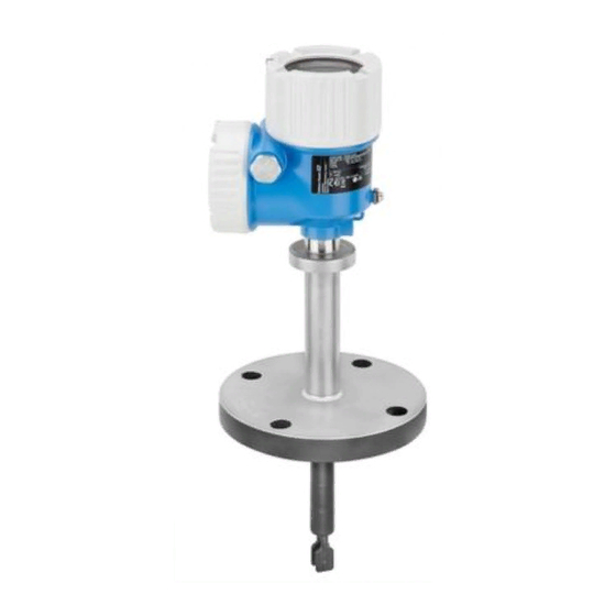
Point level switch for liquids in high-temperature applications
Hide thumbs
Also See for Liquiphant FTL64:
- Operating instructions manual (64 pages) ,
- Technical information (52 pages) ,
- Brief operating instructions (41 pages)

Related Manuals for Endress+Hauser Liquiphant FTL64


Summary of Contents for Endress+Hauser Liquiphant FTL64
- Page 1 Products Solutions Services BA02037F/00/EN/03.22-00 71560856 2022-02-18 Valid from 01.01.zz (Device firmware) Operating Instructions Liquiphant FTL64 Vibronic Point level switch for liquids in high-temperature applications...
- Page 2 Liquiphant FTL64 Order code: XXXXX-XXXXXX Ser. no.: XXXXXXXXXXXX Ext. ord. cd.: XXX.XXXX.XX Serial number www.endress.com/deviceviewer Endress+Hauser Operations App A0023555 Endress+Hauser...
-
Page 3: Table Of Contents
Liquiphant FTL64 Table of contents Table of contents About this document ....5 Electrical connection ....17 Purpose of this document . - Page 4 Table of contents Liquiphant FTL64 14.3.6 Degree of protection ... . . 59 Operation ......44 14.3.7 Vibration resistance .
-
Page 5: About This Document
Liquiphant FTL64 About this document About this document Purpose of this document These Operating Instructions contain all the information that is required in the various phases of the life cycle of the device: from product identification, incoming acceptance and storage, to mounting, connection, operation and commissioning through to troubleshooting, maintenance and disposal. -
Page 6: Symbols In Graphics
Registered trademarks Bluetooth® The Bluetooth® word mark and logos are registered trademarks owned by the Bluetooth SIG, Inc. and any use of such marks by Endress+Hauser is under license. Other trademarks and trade names are those of their respective owners. Apple®... -
Page 7: Workplace Safety
It meets the general safety standards and legal requirements. It also complies with the EU directives listed in the device-specific EU Declaration of Conformity. Endress+Hauser confirms this by affixing the CE mark to the device. Functional Safety SIL (optional) The Functional Safety Manual must be strictly observed for devices that are used in functional safety applications. -
Page 8: It Security
Product description Liquiphant FTL64 IT security We only provide a warranty if the device is installed and used as described in the Operating Instructions. The device has safety mechanisms integrated to prevent users from inadvertently changing settings. Provide additional protection for the device and data transfer to/from the device ‣... -
Page 9: Incoming Acceptance And Product
All of the information on the measuring device is displayed along with an overview of the scope of technical documentation provided. • Enter the serial number on the nameplate into the Endress+Hauser Operations app or scan the 2-D matrix code on the nameplate with the Endress+Hauser Operations app 4.2.1... -
Page 10: Transporting The Device
Mounting Liquiphant FTL64 Storage temperature –40 to +80 °C (–40 to +176 °F) Optional: –50 °C (–58 °F), –60 °C (–76 °F) 4.3.2 Transporting the device • Transport the device to the measuring point in the original packaging • Hold the device by the housing, temperature spacer, flange or extension pipe Take suitable measures to protect the coating! •... -
Page 11: Mounting Requirements
Liquiphant FTL64 Mounting A0042329 3 Installation examples for a vessel, tank or pipe Vessel insulation (example with temperature spacer) If process temperatures are high, the device should be included in a vessel insulation system to prevent the electronics from heating as a result of thermal radiation or convection. -
Page 12: Take Switch Point Into Consideration
Mounting Liquiphant FTL64 5.1.2 Take switch point into consideration The following are typical switch points, depending on the orientation of the point level switch. Water +23 °C (+73 °F) Minimum distance between the fork tip and the tank wall or pipe wall: 10 mm (0.39 in) -
Page 13: Avoid Buildup
Liquiphant FTL64 Mounting > 40 (1.57) A0042335 7 Installation example for a highly viscous liquid. Unit of measurement mm (in) 5.1.4 Avoid buildup • Use short installation sockets to ensure that the tuning fork projects freely into the vessel •... -
Page 14: Support The Device
Mounting Liquiphant FTL64 A0042340 9 Take clearance into consideration 5.1.6 Support the device NOTICE If the device is supported incorrectly, shocks and vibrations can damage the coated surface. ‣ Only use suitable supports. Support the device in the event of severe dynamic load. Maximum lateral loading capacity of the pipe extensions and sensors: 75 Nm (55 lbf ft). -
Page 15: Mounting The Device
Liquiphant FTL64 Mounting Mounting the device 5.2.1 Required tool • Open-ended wrench for sensor installation • Allen key for housing locking screw 5.2.2 Installation Align the tuning fork using the marking The tuning fork can be aligned using the marking in such a way that the medium drains off easily and buildup is avoided. -
Page 16: Sliding Sleeves
Mounting Liquiphant FTL64 A0042423 13 Screwing in the device Aligning the cable entry 4 3.5 Nm A0042355 14 Housing with external locking screw and drip loop The locking screw is not tightened when the device is delivered. 1. Loosen the external locking screw (maximum 1.5 turns). -
Page 17: Electrical Connection
Liquiphant FTL64 Electrical connection For example: • Process temperature • Process pressure • Ambient temperature • Measuring range Are the measuring point number and labeling correct (visual inspection)? Is the device adequately protected from wet conditions and direct sunlight? ... -
Page 18: Connecting The Device
Electrical connection Liquiphant FTL64 Connecting the device Housing thread The thread of the electronics and connection compartment is coated with lubricant varnish. Avoid additional lubrication. 6.3.1 2-wire AC (electronic insert FEL61) • Two-wire AC version • Switches the load directly into the power supply circuit via an electronic switch; always connect in series with a load •... - Page 19 Liquiphant FTL64 Electrical connection U 19...253 V AC I max: 350 mA >0,7 >0,5 L1 N A0036060 16 2-wire AC, electronic insert FEL61 Behavior of switch output and signaling ΔU <3.8 mA ΔU <3.8 mA <3.8 mA A0031901 17...
-
Page 20: 3-Wire Dc-Pnp (Electronic Insert Fel62)
Electrical connection Liquiphant FTL64 Selection tool for relays 207 230 253 A0042052 18 Recommended minimum holding power/rated power for load Holding power/rated power in [VA] Operating voltage in [V] AC mode • Operating voltage: 24 V, 50 Hz/60 Hz •... - Page 21 Liquiphant FTL64 Electrical connection Power consumption P ≤ 0.5 W Current consumption I ≤ 10 mA (without load) The red LED flashes in the event of an overload or short-circuit. Check for an overload or short-circuit every 5 s. Load current I ≤ 350 mA with overload and short-circuit protection...
- Page 22 Electrical connection Liquiphant FTL64 Terminal assignment U = 10...55 V DC 350 mA I max: 350 mA 55 V >0,7 >0,5 0.5 A L+ L- A0036061 19 3-wire DC-PNP, electronic insert FEL62 Connection wiring with terminals Connection wiring with M12 plug in housing as per EN61131-2 standard Behavior of switch output and signaling (L–)
-
Page 23: Universal Current Connection With Relay Output (Electronic Insert Fel64)
Liquiphant FTL64 Electrical connection 6.3.3 Universal current connection with relay output (electronic insert FEL64) • Switches the loads via 2 potential-free change-over contacts • 2 galvanically isolated change-over contacts (DPDT), both change-over contacts switch simultaneously • Functional testing without level change. A functional test can be performed on the device using the test button on the electronic insert or using the test magnet (can be ordered as an option) with the housing closed. - Page 24 Electrical connection Liquiphant FTL64 Terminal assignment >0,7 U = 19...55 V DC >0,5 U 19...253 V AC 0.5 A A0036062 21 Universal current connection with relay output, electronic insert FEL64 When bridged, the relay output works with NPN logic...
-
Page 25: Dc Connection, Relay Output (Electronic Insert Fel64 Dc)
Liquiphant FTL64 Electrical connection 6.3.4 DC connection, relay output (electronic insert FEL64 DC) • Switches the loads via 2 potential-free change-over contacts • 2 galvanically isolated change-over contacts (DPDT), both change-over contacts switch simultaneously • Functional testing without level change. Functional testing of the entire device can be performed using the test button on the electronic insert or with the test magnet (can be ordered as an option) with the housing closed. - Page 26 Electrical connection Liquiphant FTL64 Terminal assignment >0,7 >0,5 U = 9...20 V DC 0.5 A L- PE A0037685 23 DC connection with relay output, electronic insert FEL64 DC When bridged, the relay output works with NPN logic Connectable load Behavior of switch output and signaling A0033513 ...
-
Page 27: Pfm Output (Electronic Insert Fel67)
Liquiphant FTL64 Electrical connection 6.3.5 PFM output (electronic insert FEL67) • For connecting to the Nivotester FTL325P and FTL375P switching units from Endress +Hauser • PFM signal transmission; pulse frequency modulation, superimposed on the power supply along the two-wire cabling •... - Page 28 Electrical connection Liquiphant FTL64 Terminal assignment – >0,7 >0,5 L+ L- PE A0036065 25 PFM output, electronic insert FEL67 Connection wiring with terminals Connection wiring with M12 plug in housing according to EN61131-2 standard 8: Nivotester FTL325P 1 CH, FTL325P 3 CH input 1...
-
Page 29: 2-Wire Namur > 2.2 Ma/ < 1.0 Ma (Electronic Insert Fel68)
Liquiphant FTL64 Electrical connection Behavior of switch output and signaling 150 Hz 50 Hz 50 Hz 150 Hz 0 Hz A0037696 26 Switching behavior and signaling, electronic insert FEL67 MAX DIP switch for setting MAX safety mode MIN DIP switch for setting MIN safety mode... - Page 30 Electrical connection Liquiphant FTL64 Behavior of output signal • OK status: output current 2.2 to 3.8 mA • Demand mode: output current 0.4 to 1.0 mA • Alarm: output current < 1.0 mA Terminals Terminals for cable cross-section up to 2.5 mm (14 AWG).
-
Page 31: Led Module Vu120 (Optional)
Liquiphant FTL64 Electrical connection Behavior of switch output and signaling 2.2...3.8 mA 0.4...1.0 mA 2.2...3.8 mA 0.4...1.0 mA < 1.0 mA A0037694 28 Behavior of switch output and signaling, electronic insert FEL68 MAX DIP switch for setting MAX safety mode... - Page 32 Electrical connection Liquiphant FTL64 • Required tools: crimper, flat-blade screwdriver • Use the wire end ferrules supplied 1 → 2 → 3 → + – + – A0045097 A0045110 A0045111 4 → A0045112 A0045108 Operational status signaling A0039258 29 LED module, the LED lights up in green (GN), yellow (YE) or red (RD) A brightly lit LED indicates the operational status (switch status or alarm status).
-
Page 33: Bluetooth Module Vu121 (Optional)
Liquiphant FTL64 Electrical connection 6.3.8 Bluetooth module VU121 (optional) A0039257 30 Bluetooth module VU121 • The Bluetooth module can be connected via the COM interface to the following electronic inserts: FEL61, FEL62, FEL64, FEL64 DC, FEL67, FEL68 (2-wire NAMUR). • The Bluetooth module is only available in conjunction with the Heartbeat Verification + Monitoring application package. -
Page 34: Connecting The Cables
Electrical connection Liquiphant FTL64 Connecting the Bluetooth module In the case of devices for use in the hazardous area with a certain type of protection, the cover is sealed by a securing screw. For more details, see the "Cover with securing screw" section. -
Page 35: Post-Connection Check
Liquiphant FTL64 Electrical connection 24/25 mm 8.0 Nm A0018023 31 Example of coupling with cable entry, electronic insert with terminals M20 coupling (with cable entry), example Conductor cross-section maximum 2.5 mm (AWG14), ground terminal on inside in housing + terminals on the electronics Conductor cross-section maximum 4.0 mm... -
Page 36: Operation Options
Operation options Liquiphant FTL64 Operation options Overview of operation options 7.1.1 Operating concept • Operation with button and DIP switches on the electronic insert • Display with optional Bluetooth module and SmartBlue app via Bluetooth® wireless technology • Indication of operational status (switch status or alarm status) with optional LED module... -
Page 37: Led Module Vu120 (Optional)
Liquiphant FTL64 Commissioning Bluetooth module VU121 (optional) Functions • Connection via COM interface: Bluetooth module for device diagnostics via a smartphone app or tablet app • Display the battery status via app when used with electronic insert FEL68 (NAMUR) • User guidance (wizard) for SIL/WHG proof testing •... -
Page 38: Fel61 Switching Behavior And Signaling
Commissioning Liquiphant FTL64 >0,7 >0,7 >0,5 >0,5 A0037132 34 Key for functional test (electronic inserts FEL61/62/64/64DC/67/68) 1. Make sure that no undesired switching operations are triggered! 2. Press the "T" key on the electronic insert for at least 1 s (e.g. with screwdriver). -
Page 39: Fel62 Switching Behavior And Signaling
Liquiphant FTL64 Commissioning 8.2.2 FEL62 switching behavior and signaling <100 µA (L-) (L-) ΔU >1 s <100 µA <100 µA (L-) (L-) <100 µA (L-) (L-) A0039211 36 FEL62 switching behavior and signaling After the test button is pressed, the DC-PNP output is switched off for at least 10 s (I < 100 µA) even if the button is pressed for <... - Page 40 Commissioning Liquiphant FTL64 150 Hz 50 Hz >1 s 50 Hz 50 Hz 50 Hz A0039213 38 FEL67 MAX switching behavior and signaling After the test button is pressed, the output frequency is switched off (50 Hz) for at least 10 s even if the button is pressed for <...
-
Page 41: Fel68 Switching Behavior And Signaling
Liquiphant FTL64 Commissioning 8.2.5 FEL68 switching behavior and signaling 2.2 ... 3.8 mA 0.4 ... 1 mA >1 s 0.4 … 1 mA 0.4 ... 1 mA 0.4 ... 1 mA A0033543 40 NAMUR electronics switching behavior and signaling After the test button is pressed, the current is 0.4 to 1 mA for at least 10 s even if the button is pressed for... -
Page 42: Establishing A Connection Via Smartblue App
Commissioning Liquiphant FTL64 Establishing a connection via SmartBlue app 8.5.1 Prerequisites Device requirements Commissioning via SmartBlue is only possible if a Bluetooth module is installed in the device. System requirements The SmartBlue app is available for download for mobile smartphone or tablet devices in the Google Play Store for Android, and in the App Store for iOS. - Page 43 Liquiphant FTL64 Commissioning 5. Tap the icons for more information. Change the password after logging in for the first time! Saving PDF reports The PDF reports generated in the SmartBlue app are not saved automatically and must therefore be actively saved on the smartphone or tablet.
-
Page 44: Operation
Operation Liquiphant FTL64 Operation Diagnostics menu The following data can be read out via the optional Bluetooth module and the associated Endress+Hauser SmartBlue app. 9.1.1 "Diagnostics" menu Settings and information concerning diagnostics as well as help for troubleshooting Diagnostics ‣... -
Page 45: System" Menu
Liquiphant FTL64 Operation ‣ Operating mode MIN/MAX setting Density setting Switching delay uncovered to covered Switching delay covered to uncovered ‣ Output Output state 9.1.3 "System" menu System settings concerning device management, user administration or safety System Electronic type ‣... -
Page 46: Heartbeat Verification
Operation Liquiphant FTL64 Time stamp of last proof test Date of proof test Frequency at delivery status Current frequency Upper alarm frequency Upper warning frequency Lower alarm frequency Battery status Electronics temperature Minimum electronics temperature Maximum electronics temperature Heartbeat Verification The "Heartbeat Verification"... -
Page 47: Diagnostics And Troubleshooting
Liquiphant FTL64 Diagnostics and troubleshooting Diagnostics and troubleshooting The device indicates warnings and faults via Bluetooth in the SmartBlue app and via the LEDs on the electronic insert. All the device warnings and faults are for information purposes only and do not have a safety function. The faults diagnosed by the device are displayed in the SmartBlue app in accordance with NE107. -
Page 48: Firmware History
Sterilization in Place Repair 12.1 General notes 12.1.1 Repair concept Endress+Hauser repair concept • The devices have a modular design • Customers can carry out repairs For more information on service and spare parts, please contact your Endress+Hauser sales representative. Endress+Hauser... -
Page 49: Repair Of Ex-Certified Devices
WARNING Incorrect repair can affect electrical safety! Explosion Hazard! ‣ Only specialist personnel or the Endress+Hauser service team may carry out repairs on Ex-certified devices. ‣ Relevant standards and national regulations on hazardous areas, safety instructions and certificates must be observed. -
Page 50: Accessories
Accessories Liquiphant FTL64 In accordance with German law regulating the use of batteries (BattG §28 Para 1 Number 3), this symbol is used to denote electronic assemblies that must not be disposed of as household waste. Accessories 13.1 Device Viewer All the spare parts for the device, along with the order code, are listed in the Device Viewer (www.endress.com/deviceviewer). -
Page 51: Protective Cover For Single Compartment Housing, Aluminum Or 316L
Liquiphant FTL64 Accessories 13.4 Protective cover for single compartment housing, aluminum or 316L • Material: plastic • Order number: 71438291 115 (4.53) 140 (5.51) 32 (1.26) A0038280 45 Protective cover for single compartment housing, aluminum or 316L. Unit of measurement mm (in) 13.5... -
Page 52: Bluetooth Module Vu121 (Optional)
A0039257 48 Bluetooth module VU121 More detailed information and documentation are available: • Product Configurator on the Endress+Hauser website www.endress.com • Endress+Hauser sales organization www.addresses.endress.com A tall cover is required (transparent plastic cover or aluminum cover with sight glass) when using or retrofitting the Bluetooth module. -
Page 53: Sliding Sleeves For Unpressurized Operation
A0043925 49 LED module, the LED lights up in green (GN), yellow (YE) or red (RD) More detailed information and documentation are available: • Product Configurator on the Endress+Hauser website www.endress.com • Endress+Hauser sales organization www.addresses.endress.com A tall cover is required (transparent plastic cover or aluminum cover with sight glass) when using or retrofitting the Bluetooth module. -
Page 54: High Pressure Sliding Sleeves
• Weight: 0.54 kg (1.19 lb) • Order number: 52003981 • Order number: 52011891, approval: with inspection certificate EN 10204 - 3.1 material More detailed information and documentation are available: • Product Configurator on the Endress+Hauser website www.endress.com • Endress+Hauser sales organization www.addresses.endress.com 13.9... - Page 55 • Weight: 1.32 kg (2.91 lb) • Approval: with inspection certificate EN 10204 - 3.1 material • Order number: 71118695 More detailed information and documentation are available: • Product Configurator on the Endress+Hauser website www.endress.com • Endress+Hauser sales organization www.addresses.endress.com...
-
Page 56: Technical Data
Technical data Liquiphant FTL64 Technical data 14.1 Input 14.1.1 Measured variable Level (point level), MAX or MIN safety 14.1.2 Measuring range Depends on the installation location and the pipe extension ordered Standard pipe extension up to 3 m (9.8 ft) and up to 6 m (20 ft) on request. -
Page 57: Output Signal
Ex connection data See safety instructions (XA): All data relating to explosion protection are provided in separate Ex documentation and are available from the Downloads Area of the Endress+Hauser-website. The Ex documentation is supplied as standard with all Ex devices. 14.3 Environment 14.3.1... -
Page 58: Storage Temperature
Technical data Liquiphant FTL64 [°F] [°C] 158 70 -58 -50 [°C] [°F] [°F] [°C] 158 70 122 50 -58 -50 [°C] [°F] A0037923 52 Permitted ambient temperature T at the housing as a function of the process temperature T in the vessel 230 °C (446 °F) sensor... -
Page 59: Humidity
Liquiphant FTL64 Technical data 14.3.3 Humidity Operation up to 100 %. Do not open in a condensing atmosphere. 14.3.4 Operating altitude As per IEC 61010-1 Ed.3: • Up to 2 000 m (6 600 ft) above sea level • Can be extended to 3 000 m (9 800 ft) above sea level if overvoltage protection is used 14.3.5... -
Page 60: Process
In each case, the lowest value from the derating curves of the device and the selected flange applies. Devices with CRN approval: maximum 90 bar (1 305 psi) for devices with a pipe extension. Information on the Endress+Hauser website: www.endress.com →... -
Page 61: Test Pressure
Liquiphant FTL64 Technical data Process pressure range of the sensors [psi] [bar] 1450 [°C] 260 280 -14.5 [°F] 500 540 A0042363 Ordering information: Product Configurator, feature "Application": • PN: max. 100 bar (1 450 psi) max. 230 °C (446 °F) •... -
Page 62: Additional Technical Data
Technical data Liquiphant FTL64 14.5 Additional technical data Technical Documentation TI01540F. Endress+Hauser... -
Page 63: Index
Liquiphant FTL64 Index Index Workplace safety ......7 About this document Symbols - description ..... . . 5 Access via Bluetooth®... - Page 64 *71560856* 71560856 www.addresses.endress.com...