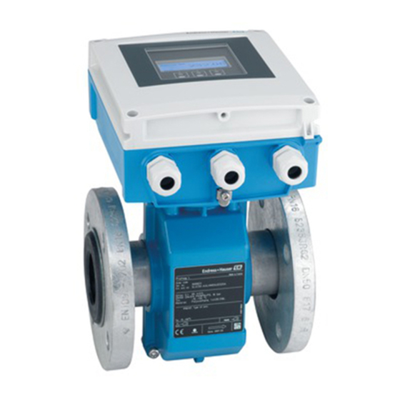
Endress+Hauser Proline Promag L 400 Operating Instructions Manual
Profibus dp electromagnetic flowmeter
Hide thumbs
Also See for Proline Promag L 400:
- Operating instructions manual (184 pages) ,
- Brief operating instructions (60 pages)

Related Manuals for Endress+Hauser Proline Promag L 400


Summary of Contents for Endress+Hauser Proline Promag L 400
-
Page 1: Operating Instructions
Products Solutions Services BA01233D/06/EN/02.14 71258939 Valid as of version 01.00.zz (Device firmware) Operating Instructions Proline Promag L 400 PROFIBUS DP Electromagnetic flowmeter... - Page 2 • The manufacturer reserves the right to modify technical data without prior notice. Your Endress+Hauser Sales Center will supply you with current information and updates to these Instructions. Endress+Hauser...
-
Page 3: Table Of Contents
Proline Promag L 400 PROFIBUS DP Table of contents Table of contents 6.2.2 Preparing the measuring device ..23 Document information ....6 6.2.3... - Page 4 ....87 13.3 Endress+Hauser services ....117 10.7.4 Performing electrode cleaning ..89 10.8 Simulation .
- Page 5 Proline Promag L 400 PROFIBUS DP Table of contents 14.5.2 Disposing of the measuring device . . 119 Accessories ..... . 120 15.1 Device-specific accessories .
-
Page 6: Document Information
Document information Proline Promag L 400 PROFIBUS DP Document information Document function These Operating Instructions contain all the information that is required in various phases of the life cycle of the device: from product identification, incoming acceptance and storage, to mounting, connection, operation and commissioning through to troubleshooting, maintenance and disposal. -
Page 7: Symbols For Certain Types Of Information
• The W@M Device Viewer : Enter the serial number from the nameplate (www.endress.com/deviceviewer) • The Endress+Hauser Operations App: Enter the serial number from the nameplate or scan the 2-D matrix code (QR code) on the nameplate. For a detailed list of the individual documents along with the documentation code... -
Page 8: Standard Documentation
Registered trademark of the PROFIBUS User Organization, Karlsruhe, Germany ® Microsoft Registered trademark of the Microsoft Corporation, Redmond, Washington, USA Applicator ® , FieldCare ® , Field Xpert , HistoROM ® , Heartbeat Technology Registered or registration-pending trademarks of the Endress+Hauser Group Endress+Hauser... -
Page 9: Basic Safety Instructions
‣ Observe the specified pressure and temperature range. Verification for borderline cases: ‣ For special fluids and fluids for cleaning, Endress+Hauser is glad to provide assistance in verifying the corrosion resistance of fluid-wetted materials, but does not accept any Endress+Hauser... -
Page 10: Workplace Safety
If a plastic transmitter housing is permanently exposed to certain steam and air mixtures, this can damage the housing. ‣ If you are unsure, please contact your Endress+Hauser Sales Center for clarification. ‣ If used in an approval-related area, observe the information on the nameplate. -
Page 11: It Security
Proline Promag L 400 PROFIBUS DP Basic safety instructions IT security We only provide a warranty if the device is installed and used as described in the Operating Instructions. The device is equipped with security mechanisms to protect it against any inadvertent changes to the device settings. -
Page 12: Product Description
Product description Proline Promag L 400 PROFIBUS DP Product description The device consists of a transmitter and a sensor. Two device versions are available: • Compact version - the transmitter and sensor form a mechanical unit. • Remote version – the transmitter and sensor are mounted separately from one another. -
Page 13: Incoming Acceptance And Product
• If one of the conditions is not satisfied, contact your Endress+Hauser Sales Center. • Depending on the device version, the CD-ROM might not be part of the delivery! The Technical Documentation is available via the Internet or via the Endress+Hauser Operations App, see the "Product identification"... -
Page 14: Transmitter Nameplate
"Supplementary device-dependent documentation" (→ 8) • The W@M Device Viewer: Enter the serial number from the nameplate (www.endress.com/deviceviewer) • The Endress+Hauser Operations App: Enter the serial number from the nameplate or scan the 2-D matrix code (QR code) on the nameplate. 4.2.1... -
Page 15: Sensor Nameplate
Proline Promag L 400 PROFIBUS DP Incoming acceptance and product identification 4.2.2 Sensor nameplate Order Code: Ser.No.: Ext. ord. cd.: Material: Patents Date: A0017186 3 Example of sensor nameplate Name of the sensor Manufacturing location Order code Serial number (ser. no.) Extended order code (ext. -
Page 16: Symbols On Measuring Device
Incoming acceptance and product identification Proline Promag L 400 PROFIBUS DP 4.2.3 Symbols on measuring device Symbol Meaning WARNING! This symbol alerts you to a dangerous situation. Failure to avoid this situation can result in serious or fatal injury. Reference to documentation Refers to the corresponding device documentation. -
Page 17: Storage And Transport
Proline Promag L 400 PROFIBUS DP Storage and transport Storage and transport Storage conditions Observe the following notes for storage: • Store in the original packaging to ensure protection from shock. • Do not remove protective covers or protective caps installed on process connections. -
Page 18: Measuring Devices With Lifting Lugs
Storage and transport Proline Promag L 400 PROFIBUS DP 5.2.2 Measuring devices with lifting lugs CAUTION Special transportation instructions for devices with lifting lugs ‣ Only use the lifting lugs fitted on the device or flanges to transport the device. -
Page 19: Installation
Proline Promag L 400 PROFIBUS DP Installation Installation Installation conditions 6.1.1 Mounting position Mounting location A0023343 Preferably install the sensor in an ascending pipe, and ensure a sufficient distance to the next pipe elbow: h ≥ 2 × DN To prevent measuring errors arising from accumulation of gas bubbles in the measuring tube, avoid the following mounting locations in the pipe: •... - Page 20 Installation Proline Promag L 400 PROFIBUS DP A0017063 Orientation The direction of the arrow on the sensor nameplate helps you to install the sensor according to the flow direction (direction of medium flow through the piping). An optimum orientation position helps avoid gas and air accumulations and deposits in the measuring tube.
-
Page 21: Requirements From Environment And Process
• Avoid direct exposure to weather conditions. • Protect the display against impact. • Protect the display from abrasion by sand in desert areas. A display protector can be ordered from Endress+Hauser: "Accessories" section (→ 120) System pressure A0015594 Never install the sensor on the pump suction side in order to avoid the risk of low pressure, and thus damage to the liner. - Page 22 Installation Proline Promag L 400 PROFIBUS DP • For information on the liner' s resistance to partial vacuum (→ 130) • Information on the shock resistance of the measuring system (→ 129) • Information on the vibration resistance of the measuring system (→ 129) Vibrations In the event of very strong vibrations, the pipe and sensor must be supported and fixed.
-
Page 23: Special Mounting Instructions
Proline Promag L 400 PROFIBUS DP Installation 6.1.3 Special mounting instructions Display protection ‣ To ensure that the optional display protection can be easily opened, maintain the following minimum head clearance: 350 mm (13.8 in) Mounting the measuring device 6.2.1... - Page 24 Installation Proline Promag L 400 PROFIBUS DP A0013964 Mounting the seals CAUTION An electrically conductive layer could form on the inside of the measuring tube! Risk of measuring signal short circuit. ‣ Do not use electrically conductive sealing compounds such as graphite.
- Page 25 Proline Promag L 400 PROFIBUS DP Installation Nominal Pressure rating Threaded Max. screw tightening torque [Nm] diameter fasteners [mm] [bar] [mm] Hard rubber Polyurethane PTFE PN 16 16 × M27 – PN 6 16 × M20 – PN 10 20 × M24 –...
- Page 26 Installation Proline Promag L 400 PROFIBUS DP Screw tightening torques for ASME B16.5, Class 150 Nominal diameter Threaded fasteners Max. screw tightening torque [Nm] ([lbf · ft]) [mm] [in] [in] Hard rubber Polyurethane PTFE 4 × 5/8 – 15 (11) 40 (29) 4 ×...
-
Page 27: Mounting The Transmitter Of The Remote Version
Proline Promag L 400 PROFIBUS DP Installation Nominal diameter Threaded fasteners Max. screw tightening torque [Nm] [mm] [mm] Hard rubber Polyurethane PTFE 20 × M30 – – 20 × M30 – – 24 × M30 – – 1 000 24 × M30 –... - Page 28 Installation Proline Promag L 400 PROFIBUS DP Wall mounting 17 (0.67) 14 (0.55) 5.8 (0.23) 5.8 (0.23) 149 (5.85) A0020523 6 Engineering unit mm (in) 1. Drill the holes. 2. Insert wall plugs into the drilled holes. 3. Screw in the securing screws slightly at first.
-
Page 29: Turning The Transmitter Housing
Proline Promag L 400 PROFIBUS DP Installation ø TX 25 20…70 ø ( 0.79…2.75) SW 8 A0020705 7 Engineering unit mm (in) 6.2.5 Turning the transmitter housing To provide easier access to the connection compartment or display module, the transmitter housing can be turned. - Page 30 Installation Proline Promag L 400 PROFIBUS DP TX 20 A0021604 4 mm A0021605 1. Loosen the fixing screws of the housing cover (when reassembling, pay attention to the tightening torque (→ 31)). 2. Open the housing cover. 3. Unlock the display module.
-
Page 31: Turning The Display Module
Proline Promag L 400 PROFIBUS DP Installation Step Fixing screw Tightening torques for housing made of: Aluminum Plastic Housing cover 2.5 Nm (1.8 lbf ft) 1 Nm (0.7 lbf ft) Smart sensor electronics module 0.6 Nm (0.4 lbf ft) Main electronics module 1.5 Nm (1.1 lbf ft) -
Page 32: Post-Installation Check
Installation Proline Promag L 400 PROFIBUS DP Reassembling the transmitter housing WARNING Excessive tightening torque applied to the fixing screws! Damage to the transmitter. ‣ When reassembling, tighten the fixing screws as per the tightening torque: Step Fixing screw Tightening torque for housing made of:... -
Page 33: Electrical Connection
Proline Promag L 400 PROFIBUS DP Electrical connection Electrical connection The measuring device does not have an internal circuit breaker. For this reason, assign the measuring device a switch or power-circuit breaker so that the power supply line can be easily disconnected from the mains. - Page 34 Electrical connection Proline Promag L 400 PROFIBUS DP Connecting cable for remote version Electrode cable Standard cable 3 ×0.38 mm (20 AWG) with common, braided copper shield ( ~7 mm (0.28 in) and individual shielded cores Cable for empty pipe 4 ×0.38 mm...
-
Page 35: Terminal Assignment
Proline Promag L 400 PROFIBUS DP Electrical connection Grounding is by means of the ground terminal provided for the purpose inside the connection housing. The stripped and twisted lengths of cable shield to the ground terminal must be as short as possible. -
Page 36: Preparing The Measuring Device
Electrical connection Proline Promag L 400 PROFIBUS DP PROFIBUS DP signal transmission Order code for "Output" and "Input" Terminal numbers 26 (RxD/TxD-P) 27 (RxD/TxD-N) Option L Order code for "Output": Option L: PROFIBUS DP, for use in non-hazardous areas and Zone 2/div. 2... - Page 37 Proline Promag L 400 PROFIBUS DP Electrical connection Transmitter Electrode cable Coil current cable 90 (3.54)* 100 (3.94)* 70 (2.76) 80 (3.15) 50 (1.97) 50 (1.97) 17 (0.67) 8 (0.31) 10 (0.39) 8 (0.31) A0021325 11 Engineering unit mm (in) A0021324 ...
-
Page 38: Connecting The Measuring Device
Electrical connection Proline Promag L 400 PROFIBUS DP Sensor Electrode cable Coil current cable 20 (0.79)* 20 (0.79)* 160 (6.30)* 170 (6.69)* 80 (3.15) 70 (2.76) 50 (1.97) 50 (1.97) 18.5 (0.73) 10 (0.39) 6 (0.24) 8 (0.31) ³1 (0.04) - Page 39 Proline Promag L 400 PROFIBUS DP Electrical connection 3. Connect the transmitter. TX 20 6 5 7 8 4 37 36 42 41 A0017445 12 Transmitter: main electronics module with terminals 1. Loosen the 4 fixing screws on the housing cover.
-
Page 40: Connecting The Transmitter
Electrical connection Proline Promag L 400 PROFIBUS DP 7. WARNING! Housing degree of protection may be voided due to insufficient sealing of the housing. Screw in the screw without using any lubricant. The threads on the cover are coated with a dry lubricant. -
Page 41: Ensuring Potential Equalization
Proline Promag L 400 PROFIBUS DP Electrical connection 7.2.3 Ensuring potential equalization CAUTION Electrode damage can result in the complete failure of the device! ‣ Make sure that the fluid and sensor have the same electrical potential. ‣ Pay attention to internal grounding concepts in the company. - Page 42 Electrical connection Proline Promag L 400 PROFIBUS DP Plastic pipe or pipe with insulating liner This connection method also applies in situations where: • The customary potential equalization is not used • Equalizing currents are present Ground cable Copper wire, at least6 mm (0.0093 in...
-
Page 43: Special Connection Instructions
Proline Promag L 400 PROFIBUS DP Electrical connection Special connection instructions 7.3.1 Connection examples PROFIBUS DP A0021429 18 Connection example for PROFIBUS DP, non-hazardous area and Zone 2/Div. 2 Control system (e.g. PLC) Cable shield: the cable shield must be grounded at both ends to comply with EMC requirements; observe cable specifications (→... -
Page 44: Enabling The Terminating Resistor
Electrical connection Proline Promag L 400 PROFIBUS DP 1. Loosen the 4 fixing screws on the housing cover. 2. Disable software addressing (OFF) via the top DIP switch 4 (SW). 3. Set the desired device address via the corresponding DIP switches. -
Page 45: Post-Connection Check
Proline Promag L 400 PROFIBUS DP Electrical connection A0013960 5. Insert dummy plugs into unused cable entries. Post-connection check Are cables or the device undamaged (visual inspection)? Do the cables comply with the requirements (→ 33)? ... -
Page 46: Operation Options
Operation options Proline Promag L 400 PROFIBUS DP Operation options Overview of operation options A0019091 Local operation via display module Computer with Web browser (e.g. Internet Explorer) or with operating tool (e.g. FieldCare, AMS Device Manager, SIMATIC PDM) Control system (e.g. PLC) -
Page 47: Structure And Function Of The Operating Menu
Proline Promag L 400 PROFIBUS DP Operation options Structure and function of the operating menu 8.2.1 Structure of the operating menu For an overview of the operating menu with menus and parameters (→ 148) Operating menu for operators and maintenances... -
Page 48: Operating Philosophy
Operation options Proline Promag L 400 PROFIBUS DP 8.2.2 Operating philosophy The individual parts of the operating menu are assigned to certain user roles (operator, maintenance etc.). Each user role contains typical tasks within the device lifecycle. Menu User role and tasks... -
Page 49: Access To The Operating Menu Via The Local Display
Proline Promag L 400 PROFIBUS DP Operation options Access to the operating menu via the local display 8.3.1 Operational display X X X X X X X 1120.50 A0016502 Operational display Device tag (→ 77) Status area Display area for measured values (4-line) Operating elements (→... -
Page 50: Navigation View
Operation options Proline Promag L 400 PROFIBUS DP Measurement channel numbers Symbol Meaning Measurement channel 1 to 4 The measurement channel number is displayed only if more than one channel is present for the same measured variable type (e.g. Totalizer 1 to 3). - Page 51 Proline Promag L 400 PROFIBUS DP Operation options Status area The following appears in the status area of the navigation view in the top right corner: • Of the submenu – The direct access code for the parameter you are navigating to (e.g. 0022-1) –...
-
Page 52: Editing View
Operation options Proline Promag L 400 PROFIBUS DP 8.3.3 Editing view Numeric editor Text editor A0013941 A0013999 Editing view Display area of the entered values Input mask Operating elements (→ 53) Input mask The following input symbols are available in the input mask of the numeric and text editor:... -
Page 53: Operating Elements
Proline Promag L 400 PROFIBUS DP Operation options Selection of letters from a to z. abc _ … Selection of special characters. "'^ _ … ~& Confirms selection. Switches to the selection of the correction tools. Exits the input without applying the changes. -
Page 54: Opening The Context Menu
Operation options Proline Promag L 400 PROFIBUS DP Meaning Enter key For operational display • Pressing the key briefly opens the operating menu. • Pressing the key for 2 s opens the context menu. In a menu, submenu • Pressing the key briefly: –... - Page 55 Proline Promag L 400 PROFIBUS DP Operation options The context menu is closed and the operational display appears. Calling up the menu via the context menu 1. Open the context menu. 2. Press to navigate to the desired menu.
-
Page 56: Navigating And Selecting From List
Operation options Proline Promag L 400 PROFIBUS DP 8.3.6 Navigating and selecting from list Different operating elements are used to navigate through the operating menu. The navigation path is displayed on the left in the header. Icons are displayed in front of the individual menus. -
Page 57: Calling Up Help Text
Proline Promag L 400 PROFIBUS DP Operation options Navigation path "Expert" menu → Direct access The direct access code consists of a 4-digit number and the channel number, which identifies the channel of a process variable: e.g. 0914-1. In the navigation view, this appears on the right-hand side in the header of the selected parameter. -
Page 58: Changing The Parameters
Operation options Proline Promag L 400 PROFIBUS DP 8.3.9 Changing the parameters For a description of the editing display - consisting of text editor and numeric editor - with symbols (→ 52), for a description of the operating elements (→ 53) Example: Changing the tag name in the "Tag description"... -
Page 59: User Roles And Related Access Authorization
Proline Promag L 400 PROFIBUS DP Operation options Ent. access code Invalid or out of range input value Min:0 Max:9999 A0014049-EN 8.3.10 User roles and related access authorization The two user roles "Operator" and "Maintenance" have different write access to the parameters if the customer defines a user-specific access code. -
Page 60: Access To The Operating Menu Via The Web Browser
Operation options Proline Promag L 400 PROFIBUS DP Switching on the keypad lock The keypad lock is switched on automatically: • Each time the device is restarted. • If the device has not been operated for longer than one minute in the measured value display. -
Page 61: Establishing A Connection
Proline Promag L 400 PROFIBUS DP Operation options User rights for TCP/IP settings User rights required for TCP/IP settings (e.g. for changes to IP address, subnet mask) Computer configuration • JavaScript is enabled • If JavaScript cannot be enabled, enter http://192.168.1.212/basic.html in the address line of the Web browser. -
Page 62: Logging On
Operation options Proline Promag L 400 PROFIBUS DP 8.4.4 Logging on 1. Select the preferred operating language for the Web browser. 2. Enter the access code. 3. Press OK to confirm your entry. Access code 0000 (factory setting); can be changed by customer (→ 91) If no action is performed for 10 minutes, the Web browser automatically returns to the login page. -
Page 63: Disabling The Web Server
Proline Promag L 400 PROFIBUS DP Operation options Functions Meaning Configuration and checking of all the parameters required for establishing the connection Network to the device: configuration • Network settings (e.g. IP address, MAC address) • Device information (e.g. serial number, firmware version) -
Page 64: Access To The Operating Menu Via The Operating Tool
Operation options Proline Promag L 400 PROFIBUS DP Access to the operating menu via the operating tool The structure of the operating menu in the operating tools is the same as for operation via the local display. 8.5.1 Connecting the operating tool... -
Page 65: Fieldcare
FieldCare Function scope FDT-based plant asset management tool from Endress+Hauser. It can configure all smart field devices in a system and helps you manage them. By using the status information, it is also a simple but effective way of checking their status and condition. - Page 66 Operation options Proline Promag L 400 PROFIBUS DP User interface Xxxxx Xxxxx A0021053-EN Header Picture of device Device tag (→ 77) Status area with status signal (→ 104) Display area for current measured values (→ 94) Event list with additional functions such as save/load, events list and document creation...
-
Page 67: System Integration
Proline Promag L 400 PROFIBUS DP System integration System integration Overview of device description files 9.1.1 Current version data for the device Firmware version 01.00.zz • On the title page of the Operating instructions • On transmitter nameplate (→ 14) •... -
Page 68: Profile Gsd
System integration Proline Promag L 400 PROFIBUS DP The fact that the manufacturer-specific GSD should be used is specified in the Ident number selector parameter by selecting the Manufacturer option. Where to acquire the manufacturer-specific GSD: www.endress.com → Download Area 9.2.2... -
Page 69: Cyclic Data Transmission
Proline Promag L 400 PROFIBUS DP System integration • If the Promag 400 PROFIBUS DP is acyclically configured via an operating program (Class 2 master), access is directly via the block structure or the parameters of the measuring device. • If parameters have been changed in the device to be replaced (Promag 50... -
Page 70: Description Of The Modules
System integration Proline Promag L 400 PROFIBUS DP Discrete Output block 1 to (→ 74) Input values DO ← Defined order of modules The measuring device works as a modular PROFIBUS slave. In contrast to a compact slave, a modular slave has a variable design and consists of several individual modules. The device master file (GSD) contains a description of the individual modules (input and output data) along with their individual properties. - Page 71 Proline Promag L 400 PROFIBUS DP System integration Factory setting Function block Factory setting AI 1 Volume flow AI 2 Mass flow AI 3 Electronics temperature AI 4 Flow velocity Data structure Input data of Analog Input Byte 1 Byte 2...
- Page 72 System integration Proline Promag L 400 PROFIBUS DP Selection: control totalizer CHANNEL Value SETTOT Control totalizer 33310 Totalize 33046 Resetting 33308 Adopt totalizer initial setting Factory setting Function block Factory setting: Value SETTOT (meaning) Totalizer 1, 2 and 3 0 (totalizing)
- Page 73 Proline Promag L 400 PROFIBUS DP System integration Input data of TOTAL Byte 1 Byte 2 Byte 3 Byte 4 Byte 5 Measured value: floating point number (IEEE 754) Status AO module (Analog Output) Transmit a compensation value from the PROFIBUS master (Class 1) to the measuring device.
- Page 74 System integration Proline Promag L 400 PROFIBUS DP Factory setting Function block Factory setting DI 1 Empty pipe detection DI 2 Low flow cut off Data structure Input data of Discrete Input Byte 1 Byte 2 Discrete Status DO module (Discrete Output) Transmit discrete output values from the PROFIBUS master (Class 1) to the measuring device.
-
Page 75: Commissioning
Proline Promag L 400 PROFIBUS DP Commissioning Commissioning 10.1 Function check Before commissioning the device, make sure that the post-installation and post- connection checks have been performed. • "Post-installation check" checklist (→ 32) • "Post-connection check" checklist (→ 45) 10.2... -
Page 76: Configuring The Measuring Device
Commissioning Proline Promag L 400 PROFIBUS DP X X X X X X X 20.50 Main menu 0104-1 Language English Operation Setup Language 0104-1 English à Deutsch Español Français Language 0104-1 à English Deutsch Español Français Hauptmenü 0104-1 Sprache Deutsch... -
Page 77: Defining The Tag Name
Proline Promag L 400 PROFIBUS DP Commissioning System units (→ 77) Communication (→ 80) Display (→ 78) Analog inputs (→ 81) Low flow cut off (→ 81) Empty pipe detection (→ 83) Advanced setup (→... -
Page 78: Configuring The Local Display
Commissioning Proline Promag L 400 PROFIBUS DP Conductivity unit Temperature unit Mass flow unit Mass unit Density unit Parameter overview with brief description Parameter Description Selection Factory setting Volume flow unit Select volume flow unit. Unit choose list Country-specific: • l/h Result •... - Page 79 Proline Promag L 400 PROFIBUS DP Commissioning Navigation "Setup" menu → Display Structure of the wizard Format display Value 1 display 0% bargraph value 1 100% bargraph value 1 Value 2 display Value 3 display 0% bargraph value 3 100% bargraph...
-
Page 80: Configuring The Communication
Commissioning Proline Promag L 400 PROFIBUS DP Parameter Description Selection / User entry Factory setting 0% bargraph value 1 Enter 0% value for bar graph display. Signed floating-point number 0 l/h 100% bargraph value 1 Enter 100% value for bar graph display. -
Page 81: Configuring The Analog Inputs
Proline Promag L 400 PROFIBUS DP Commissioning 10.6.5 Configuring the analog inputs The Analog inputs submenu guides you systematically to the individual Analog input 1 to 4 submenu. From here you get to the parameters of the individual analog input. - Page 82 Commissioning Proline Promag L 400 PROFIBUS DP Structure of the wizard Assign variable Volume flow Mass flow On value Off value Pres. shock sup. End of wizard A0020524-EN 27 "Low flow cut off" wizard in the "Setup" menu Parameter overview with brief description...
-
Page 83: Configuring Empty Pipe Detection
Proline Promag L 400 PROFIBUS DP Commissioning 10.6.7 Configuring empty pipe detection The Empty pipe detection wizard guides you systematically through all the parameters that have to be set for configuring the low flow cut off. Navigation "Setup" menu → Empty pipe detection Structure of the wizard Empty pipe det. -
Page 84: Advanced Settings
Commissioning Proline Promag L 400 PROFIBUS DP 10.7 Advanced settings The Advanced setup submenu with its submenus contains parameters for specific settings. Navigation to the "Advanced setup" submenu X X X X X X X 20.50 0104-1 Main menu Language English Display/operat. -
Page 85: Carrying Out A Sensor Adjustment
Proline Promag L 400 PROFIBUS DP Commissioning Device reset (→ 113) Order code for "Application package", option EC "ECC electrode cleaning" 10.7.1 Carrying out a sensor adjustment The Sensor adjustment submenu contains parameters that pertain to the functionality of the sensor. - Page 86 Commissioning Proline Promag L 400 PROFIBUS DP Parameter Description Selection Factory setting Control Totalizer 1 to 3 Control totalizer value. • Totalize Totalize • Reset + hold • Preset + hold Totalizer operation mode • Net flow total Net flow total •...
-
Page 87: Carrying Out Additional Display Configurations
Proline Promag L 400 PROFIBUS DP Commissioning 10.7.3 Carrying out additional display configurations In the "Display" submenu you can set all the parameters involved in the configuration of the local display. Navigation "Setup" menu → Advanced setup → Display ‣... - Page 88 Commissioning Proline Promag L 400 PROFIBUS DP Parameter overview with brief description Parameter Description Selection / User entry Factory setting Format display Select how measured values are shown on • 1 value, max. size 1 value, max. size the display. • 1 bargraph + 1 value •...
-
Page 89: Performing Electrode Cleaning
Proline Promag L 400 PROFIBUS DP Commissioning Parameter Description Selection / User entry Factory setting Display language Set display language. • English English (alternatively, the • Deutsch ordered language is preset in • Français the device) • Español • Italiano • Nederlands •... -
Page 90: Simulation
Commissioning Proline Promag L 400 PROFIBUS DP Parameter overview with brief description Parameter Description Selection / User entry / User Factory setting interface Electrode cleaning circuit Enable the cyclic electrode cleaning circuit. • Off • On ECC duration Enter the duration of electrode cleaning in 0.01 to 30 s... -
Page 91: Protecting Settings From Unauthorized
Proline Promag L 400 PROFIBUS DP Commissioning Parameter overview with brief description Parameter Prerequsite Description Selection / User Factory setting entry Assign simulation process variable – Select a process variable for • Off the simulation process that is • Volume flow activated. -
Page 92: Write Protection Via Write Protection
Commissioning Proline Promag L 400 PROFIBUS DP The device automatically locks the write-protected parameters again if a key is not pressed for 10 minutes in the navigation and editing view. The device locks the write-protected parameters automatically after 60 s if the user skips back to the operational display mode from the navigation and editing view. - Page 93 Proline Promag L 400 PROFIBUS DP Commissioning the -symbol appears in front of the parameters in the header of the operational display and in the navigation view. X X X X X X X 20.50 A0015870 If hardware write protection is disabled, no option is displayed in the Locking status parameter (→...
-
Page 94: Operation
Operation Proline Promag L 400 PROFIBUS DP Operation 11.1 Reading device locking status The write protection types that are currently active can be determined using the Locking status parameter. Navigation "Operation" menu → Locking status Function scope of "Locking status" parameter... -
Page 95: Totalizer
Proline Promag L 400 PROFIBUS DP Operation Structure of the submenu Parameter overview with brief description Parameter Description User interface Volume flow Displays the volume flow currently measured. Signed floating-point number Mass flow Displays the mass flow currently calculated. Signed floating-point number Conductivity Displays the corrected volume flow currently calculated. -
Page 96: Performing A Totalizer Reset
Operation Proline Promag L 400 PROFIBUS DP 11.6 Performing a totalizer reset In the Operation submenu the totalizers are reset: Control Totalizer 1 to 3 Function scope of "Control Totalizer " parameter Options Description Totalize The totalizer is started. Reset + hold The totaling process is stopped and the totalizer is reset to 0. - Page 97 Proline Promag L 400 PROFIBUS DP Operation A0016222 30 Chart of a measured value trend • x-axis: depending on the number of channels selected displays 250 to 1000 measured values of a process variable. • y-axis: displays the approximate measured value span and constantly adapts this to the ongoing measurement.
- Page 98 Operation Proline Promag L 400 PROFIBUS DP Parameter overview with brief description Parameter Description Selection / User entry Factory setting Assign channel 1 to 4 Assign process variable to logging channel. • Off • Volume flow • Mass flow • Flow velocity •...
-
Page 99: Diagnostics And Troubleshooting
Proline Promag L 400 PROFIBUS DP Diagnostics and troubleshooting Diagnostics and troubleshooting 12.1 General troubleshooting For local display Problem Possible causes Remedy Local display dark and no output Supply voltage does not match that Apply the correct supply voltage . -
Page 100: Diagnostic Information Via Light Emitting
Diagnostics and troubleshooting Proline Promag L 400 PROFIBUS DP For access Problem Possible causes Remedy No write access to parameters Hardware write protection enabled Set the write protection switch on the main electronics module to the OFF position (→ 92). - Page 101 Proline Promag L 400 PROFIBUS DP Diagnostics and troubleshooting Color Meaning Alarm Green Measuring device is ok Flashing green Measuring device not configured Firmware error Main error Flashing red Error Flashing red/green Start measuring device Endress+Hauser...
-
Page 102: Diagnostic Information On Local Display
Diagnostics and troubleshooting Proline Promag L 400 PROFIBUS DP 12.3 Diagnostic information on local display 12.3.1 Diagnostic message Faults detected by the self-monitoring system of the measuring device are displayed as a diagnostic message in alternation with the operational display. -
Page 103: Calling Up Remedial Measures
Proline Promag L 400 PROFIBUS DP Diagnostics and troubleshooting Diagnostic behavior Symbol Meaning Alarm • Measurement is interrupted. • Signal outputs and totalizers assume the defined alarm condition. • A diagnostic message is generated. A0013961 • The background lighting changes to red. -
Page 104: Diagnostic Information In The Web Browser
Diagnostics and troubleshooting Proline Promag L 400 PROFIBUS DP The user is in the diagnostic message. 1. Press ( symbol). The Diagnostic list submenu opens. 2. Select the desired diagnostic event with or and press . -
Page 105: Calling Up Remedy Information
Proline Promag L 400 PROFIBUS DP Diagnostics and troubleshooting Symbol Meaning Out of specification The device is operated: Outside its technical specification limits (e.g. outside the process temperature range) A0017277 Maintenance required Maintenance is required. The measured value is still valid. -
Page 106: Adapting The Diagnostic Information
Diagnostics and troubleshooting Proline Promag L 400 PROFIBUS DP Diagnostic information The fault can be identified using the diagnostic information. The short text helps you by providing information about the fault. In addition, the corresponding symbol for the diagnostic behavior is displayed in front of the diagnostic information on the local display. - Page 107 Proline Promag L 400 PROFIBUS DP Diagnostics and troubleshooting Coding Measuring value (hex) Byte 5 Quality Quality Substatus Limits A0021271-EN 32 Structure of the coding byte The content of the coding byte depends on the configured failsafe mode in the particular function block.
-
Page 108: Overview Of Diagnostic Information
Diagnostics and troubleshooting Proline Promag L 400 PROFIBUS DP Diagnostic information pertaining to the electronics (diagnostic no.: 200 to 399) Measured value status (fixed assignment) Diagnostic behavior Device diagnostics Quality Coding Category (configurable) (fixed assignment) Quality Substatus (hex) (NE107) Alarm... - Page 109 Proline Promag L 400 PROFIBUS DP Diagnostics and troubleshooting Diagnostic Short text Remedy instructions Status Diagnostic number signal behavior [from the [from the factory] factory] Sensor temperature 1.Change main electronic module Alarm 2.Change sensor Sensor short circuit 1.Check sensor and cable 2.Change...
- Page 110 Diagnostics and troubleshooting Proline Promag L 400 PROFIBUS DP Diagnostic Short text Remedy instructions Status Diagnostic number signal behavior [from the [from the factory] factory] Configuration 1. Restart device Alarm incompatible 2. Contact service Dataset 1. Check data set file Warning 2.
-
Page 111: Pending Diagnostic Events
Proline Promag L 400 PROFIBUS DP Diagnostics and troubleshooting 12.8 Pending diagnostic events The Diagnostics menu allows the user to view the current diagnostic event and the previous diagnostic event separately. To call up the measures to rectify a diagnostic event: •... -
Page 112: 12.10 Event Logbook
Diagnostics and troubleshooting Proline Promag L 400 PROFIBUS DP To call up the measures to rectify a diagnostic event: • Via local display (→ 103) • Via Web browser (→ 105) • Via "FieldCare" operating tool (→ 106) 12.10 Event logbook... -
Page 113: 12.11 Resetting The Measuring Device
Proline Promag L 400 PROFIBUS DP Diagnostics and troubleshooting Info number Info name I1092 Trend data deleted I1110 Write protection switch changed I1137 Electronic changed I1151 History reset I1155 Reset electronic temperature I1156 Memory error trend I1157 Memory error event list... -
Page 114: 12.11.1 Function Scope Of "Device Reset" Parameter
Diagnostics and troubleshooting Proline Promag L 400 PROFIBUS DP ‣ Administration ‣ Define access code Define access code Confirm access code Device reset Parameter overview with brief description Parameter Description Selection Factory setting Device reset Restart or reset device manually. - Page 115 Proline Promag L 400 PROFIBUS DP Diagnostics and troubleshooting Extended order code 1 Extended order code 2 Extended order code 3 ENP version PROFIBUS ident number Status PROFIBUS Master Config IP address Subnet mask Default gateway Parameter overview with brief description...
-
Page 116: 12.13 Firmware History
"Manufacturer' s information" document. The manufacturer' s information is available: • In the Download Area of the Endress+Hauser Internet site: www.endress.com → Download • Specify the following details: –... -
Page 117: Maintenance
Replacement seals (accessory) (→ 147) 13.2 Measuring and test equipment Endress+Hauser offers a wide variety of measuring and test equipment, such as W@M or device tests. Your Endress+Hauser Sales Center can provide detailed information on the services. For a list of some of the measuring and test equipment, refer to the "Accessories"... -
Page 118: Repair
• Spare parts are grouped into logical kits with the associated Installation Instructions. • Repairs are carried out by Endress+Hauser Service or by correspondingly trained customers. • Certified devices can be converted into other certified devices by Endress+Hauser Service or at the factory only. Notes for repair and conversion For repair and modification of a measuring device, observe the following notes: •... -
Page 119: Disposing Of The Measuring Device
Proline Promag L 400 PROFIBUS DP Repair Carry out the mounting and connection steps from the chapters "Mounting the measuring device" and "Connecting the measuring device" in the logically reverse sequence. Observe the safety instructions. 14.5.2 Disposing of the measuring device WARNING Danger to personnel and environment from fluids that are hazardous to health. -
Page 120: Accessories
Various accessories, which can be ordered with the device or subsequently from Endress +Hauser, are available for the device. Detailed information on the order code in question is available from your local Endress+Hauser sales center or on the product page of the Endress+Hauser website: www.endress.com. -
Page 121: System Components
The application already contains the data of your Endress+Hauser device. Endress +Hauser also takes care of maintaining and updating the data records. -
Page 122: Technical Data
Technical data Proline Promag L 400 PROFIBUS DP Technical data 16.1 Application The measuring device described in these Instructions is intended only for flow measurement of liquids with a minimum conductivity of 5 μS/cm. Depending on the version ordered, the measuring device can also measure potentially explosive, flammable, poisonous and oxidizing media. - Page 123 Proline Promag L 400 PROFIBUS DP Technical data Nominal Recommended Factory settings diameter flow Full scale value current min./max. full scale value Pulse value Low flow cut off output (v ~ 0.3/10 m/s) (~ 2 pulse/s) (v ~ 0.04 m/s) (v ~ 2.5 m/s)
- Page 124 Technical data Proline Promag L 400 PROFIBUS DP Nominal Recommended Factory settings diameter flow Full scale value current min./max. full scale value Pulse value Low flow cut off output (v ~ 0.3/10 m/s) (~ 2 pulse/s) (v ~ 0.04 m/s) (v ~ 2.5 m/s)
-
Page 125: Output
Input signal External measured values Various pressure transmitters and temperature measuring devices can be ordered from Endress+Hauser: see "Accessories" section (→ 121) It is recommended to read in external measured values to calculate the following measured variables: Corrected volume flow... -
Page 126: Power Supply
Technical data Proline Promag L 400 PROFIBUS DP Protocol-specific data PROFIBUS DP Manufacturer ID 0x11 Ident number 0x1562 Profile version 3.02 Device description files (GSD, Information and files under: DTM, DD) • www.endress.com • www.profibus.org Output values Analog input 1 to 4 (from measuring device to •... -
Page 127: Performance Characteristics
Proline Promag L 400 PROFIBUS DP Technical data Power consumption Order code for "Output" Maximum power consumption Option L: PROFIBUS DP 30 VA/8 W Current consumption Transmitter Order code for "Power supply" Maximum Maximum Current consumption switch-on current Option L: AC 100 to 240 V 145 mA 25 A (<... - Page 128 Technical data Proline Promag L 400 PROFIBUS DP Installation • Inlet run > 10 × DN • Outlet run > 5 × DN • Sensor and transmitter grounded. • The sensor is centered in the pipe. Maximum measured error Error limits under reference operating conditions o.r.
-
Page 129: Installation
Proline Promag L 400 PROFIBUS DP Technical data 16.7 Installation "Mounting requirements" (→ 19) 16.8 Environment Ambient temperature (→ 21) range Temperature tables Observe the interdependencies between the permitted ambient and fluid temperatures when operating the device in hazardous areas. -
Page 130: Process
Technical data Proline Promag L 400 PROFIBUS DP Mechanical load • Protect the transmitter housing against mechanical effects, such as shock or impact; the use of the remote version is sometimes preferable. • Never use the transmitter housing as a ladder or climbing aid. -
Page 131: 16.10 Mechanical Construction
Proline Promag L 400 PROFIBUS DP Technical data Flow limit The diameter of the pipe and the flow rate determine the nominal diameter of the sensor. The optimum velocity of flow is between 2 to 3 m/s (6.56 to 9.84 ft/s). Also match the velocity of flow (v) to the physical properties of the fluid: •... - Page 132 Technical data Proline Promag L 400 PROFIBUS DP EN 1092-1 (DIN 2501) Order code for "Housing", option M, Q [mm] Polycarbonate plastic Weight [kg] PN 6 PN 10 PN 16 – – 1 000 1 200 1 400 1 114...
- Page 133 Proline Promag L 400 PROFIBUS DP Technical data AS 4087, PN 16 Weight [kg] [mm] Order code for "Housing", option M, Q Order code for "Housing", option A, R Polycarbonate plastic Aluminum, AlSi10Mg, coated 99.7 105.7 120.7 133.7 182.7 260.7 367.7...
- Page 134 Technical data Proline Promag L 400 PROFIBUS DP ASME B16.5, Class 150 Weight [lbs] [in] Order code for "Housing", option M, Q Order code for "Housing", option A, R Polycarbonate plastic Aluminum, AlSi10Mg, coated 140.5 151.5 303.5 371.5 422.5 504.5 667.5...
- Page 135 Proline Promag L 400 PROFIBUS DP Technical data Weight in SI units Lap joint flange; fixed flange DN ≥ 350 EN 1092-1 (DIN 2501) Weight [kg] [mm] PN 6 PN 10 PN 16 – – – – – – –...
- Page 136 Technical data Proline Promag L 400 PROFIBUS DP AS 2129, Table E Weight [mm] [kg] 1 000 1 200 1 234 AS 4087, PN 16 Weight [mm] [kg] 1 000 1 200 1 216 Lap joint flange, stamped plate EN 1092-1 (DIN 2501), PN 10...
- Page 137 Proline Promag L 400 PROFIBUS DP Technical data ASME B16.5, Class 150 Weight [in] [lbs] – AWWA C207, Class D Weight [in] [lbs] 1 030 1 288 1 471 1 980 2 800 3 508 4 692 5 656 6 858...
- Page 138 Technical data Proline Promag L 400 PROFIBUS DP Nominal diameter Pressure rating Measuring tube internal diameter EN (DIN) ASME AS 2129 Hard rubber Polyurethane PTFE AWWA AS 4087 [mm] [in] [mm] [in] [mm] [in] [mm] [in] PN 10/16 Class 150 –...
- Page 139 Proline Promag L 400 PROFIBUS DP Technical data Nominal diameter Pressure rating Measuring tube internal diameter EN (DIN) ASME AS 2129 Hard rubber Polyurethane PTFE AWWA AS 4087 [mm] [in] [mm] [in] [mm] [in] [mm] [in] – Class D –...
- Page 140 Technical data Proline Promag L 400 PROFIBUS DP Materials Transmitter housing Order Code for "Housing" • Compact version, standard: – Option A: aluminum, AlSi10Mg, coated – Option M: polycarbonate plastic • Compact version, inclined: – Option Q: polycarbonate plastic – Option R: aluminum, AlSi10Mg, coated •...
- Page 141 Proline Promag L 400 PROFIBUS DP Technical data Sensor housing • DN 50 to 300 (2 to 12"): aluminum, AlSi10Mg, coated • DN 350 to 2400 (14 to 90"): carbon steel with protective varnish Sensor connection housing Aluminum, AlSi10Mg, coated Measuring tubes •...
- Page 142 Technical data Proline Promag L 400 PROFIBUS DP AS 2129 Carbon steel, A105/FE410WB/P235GH/P265GH/S235JRG2 AS 4087 Carbon steel, A105/P265GH/S275JRG2 Seals In accordance with DIN EN 1514-1 Accessories Display protection Stainless steel, 1.4301 (304L) Ground disks • Stainless steel, 1.4435 (316L) • Alloy C22, 2.4602 (UNS N06022)
-
Page 143: 16.11 Operability
Proline Promag L 400 PROFIBUS DP Technical data 16.11 Operability Local operation Via display module A0020538 Display elements • 4-line display • White background lighting; switches to red in event of device errors • Format for displaying measured variables and status variables can be individually configured •... - Page 144 Technical data Proline Promag L 400 PROFIBUS DP Remote operation Via PROFIBUS DP network A0020903 Automation system Computer with PROFIBUS network card PROFIBUS DP network Measuring device Service interface Service interface (CDI-RJ45) PROFIBUS DP A0023114 Computer with Web browser (e.g. Internet Explorer) for accessing the integrated device Web server or with "FieldCare"...
-
Page 145: 16.12 Certificates And Approvals
EC Directives. These are listed in the corresponding EC Declaration of Conformity along with the standards applied. Endress+Hauser confirms successful testing of the device by affixing to it the CE mark. C-Tick symbol The measuring system meets the EMC requirements of the "Australian Communications and Media Authority (ACMA)". -
Page 146: 16.13 Application Packages
The application packages can be ordered from Endress+Hauser either directly with the device or subsequently. Detailed information on the order code in question is available from your local Endress+Hauser sales center or on the product page of the Endress+Hauser website: www.endress.com. -
Page 147: 16.14 Accessories
• The W@M Device Viewer : Enter the serial number from the nameplate (www.endress.com/deviceviewer) • The Endress+Hauser Operations App: Enter the serial number from the nameplate or scan the 2-D matrix code (QR code) on the nameplate. Standard documentation... -
Page 148: Appendix
Appendix Proline Promag L 400 PROFIBUS DP Appendix 17.1 Overview of the operating menu The following tables provide an overview of the entire operating menu structure with menus and parameters. The page reference indicates where a description of the parameter can be found in the manual. -
Page 149: Setup" Menu
Proline Promag L 400 PROFIBUS DP Appendix Preset value 1 to 3 (→ 96) Reset all totalizers 17.1.2 "Setup" menu Navigation Setup Setup (→ 77) Device tag (→ 77) ‣ (→ 77) System units (→... - Page 150 Appendix Proline Promag L 400 PROFIBUS DP 100% bargraph value 3 (→ 80) Value 4 display (→ 80) ‣ Analog inputs (→ 81) ‣ Analog input 1 to 4 (→ 81) Channel PV filter time (→ 81) Fail safe type (→...
- Page 151 Proline Promag L 400 PROFIBUS DP Appendix Control Totalizer 1 to 3 (→ 86) Totalizer operation mode (→ 86) Failure mode (→ 86) ‣ Display (→ 78) Format display (→ 79) Value 1 display (→ 79) 0% bargraph value 1 (→...
-
Page 152: Diagnostics" Menu
Appendix Proline Promag L 400 PROFIBUS DP ‣ Electrode cleaning circuit (→ 89) Electrode cleaning circuit (→ 90) ECC duration (→ 90) ECC recovery time (→ 90) (→ 90) ECC cleaning cycle ECC Polarity (→ 90) ‣... - Page 153 Proline Promag L 400 PROFIBUS DP Appendix ‣ Event logbook Filter options ‣ Event list ‣ Device information (→ 114) Device tag (→ 115) Serial number (→ 115) Firmware version (→ 115) (→ 115) Device name (→...
- Page 154 Appendix Proline Promag L 400 PROFIBUS DP Totalizer value 1 to 3 (→ 95) Totalizer status 1 to 3 (→ 95) Totalizer status (Hex) 1 to 3 (→ 95) ‣ Data logging (→ 96) (→ 98)
- Page 155 Proline Promag L 400 PROFIBUS DP Appendix Hour AM/PM Minute Verification mode External device information External reference voltage 1 External reference voltage 2 Start verification Progress Status Overall result ‣ Verification results Date/time Verification ID Operating time Overall result Sensor...
-
Page 156: Expert" Menu
Appendix Proline Promag L 400 PROFIBUS DP Coil current shot time Reference electrode potential against ‣ Simulation (→ 90) Assign simulation process variable (→ 91) (→ 91) Value process variable Simulation device alarm (→ 91) Simulation diagnostic event Diagnostic event category (→... - Page 157 Proline Promag L 400 PROFIBUS DP Appendix ‣ Analog outputs (→ 166) ‣ Discrete outputs (→ 167) ‣ Application (→ 167) ‣ Diagnostics (→ 169) "System" submenu Navigation Expert → System ‣ System ‣ Display (→...
- Page 158 Appendix Proline Promag L 400 PROFIBUS DP Header (0097) (→ 89) Header text (0112) (→ 89) Separator (0101) (→ 89) Contrast display (0105) (→ 89) Backlight (0111) Access status display (0091) ‣ Diagnostic handling Alarm delay (0651) ‣...
- Page 159 Proline Promag L 400 PROFIBUS DP Appendix Activate SW option (0029) Software option overview (0015) "Sensor" submenu Navigation Expert → Sensor ‣ Sensor ‣ Measured values ‣ Process variables (→ 94) Volume flow (1838) (→ 95) Mass flow (1847) (→...
- Page 160 Appendix Proline Promag L 400 PROFIBUS DP ‣ Process parameters Filter options (6710) Flow damping (6661) CIP filter delimiter (6705) CIP filter depth (6708) Flow override (1839) Conductivity damping (1803) Conductivity measurement (6514) ‣ Low flow cut off (→ 81) Assign process variable (1837) (→...
- Page 161 Proline Promag L 400 PROFIBUS DP Appendix ECC duration (6555) (→ 90) ECC recovery time (6556) (→ 90) ECC cleaning cycle (6557) (→ 90) ECC Polarity (6631) (→ 90) ‣ External compensation Density source (6615) External density (6630) Fixed density (6623) ‣...
- Page 162 Appendix Proline Promag L 400 PROFIBUS DP Conductivity calibration factor (6718) ‣ Logbook Calibration counter (2750) Calibration date/time (2814) Calibration date/time (2814) Calibration date/time (2814) Calibration date/time (2814) Calibration date/time (2814) Calibration date/time (2814) Calibration date/time (2814) Calibration date/time (2814)
- Page 163 Proline Promag L 400 PROFIBUS DP Appendix Calibration factor (2809) Calibration factor (2809) Calibration factor (2809) Calibration factor (2809) Calibration factor (2809) Calibration factor (2809) Calibration factor (2809) Calibration factor (2809) ‣ Testpoints Flow velocity (6510) Raw volume flow (6704)
- Page 164 Appendix Proline Promag L 400 PROFIBUS DP ‣ Communication (→ 75) ‣ PROFIBUS DP configuration Address mode (1468) Device address (1462) (→ 80) Ident number selector (1461) ‣ PROFIBUS DP info Status PROFIBUS Master Config (1465) (→ 115) PROFIBUS ident number (1464) (→...
- Page 165 Proline Promag L 400 PROFIBUS DP Appendix Manufacturer ID (1502) Device ID (1480) Serial number (1481) Diagnostics (1482) Diagnostics mask (1484) Device certification (1486) Factory reset (1488) Descriptor (1489) Device message (1490) Device install date (1491) Ident number selector (1461)
- Page 166 Appendix Proline Promag L 400 PROFIBUS DP ‣ Analog inputs (→ 81) ‣ Analog input 1 to 4 Channel (1561–1 to 4) (→ 81) PV filter time (1524–1 to 4) (→ 81) Fail safe type (1525–1 to 4) (→...
- Page 167 Proline Promag L 400 PROFIBUS DP Appendix Fail safe time (1635–1) Fail safe type (1636–1) Fail safe value (1637–1) Out value (1647–1) Out status (1669–1) Out status (1645–1) ‣ Discrete outputs ‣ Discrete output 1 to 2 Set point value (1715–1 to 2) Set point status (1714–1 to 2)
- Page 168 Appendix Proline Promag L 400 PROFIBUS DP Target mode (3834–1 to 3) Mode block actual (3801–1 to 3) Mode block permitted (3828–1 to 3) Mode block normal (3824–1 to 3) Alarm summary (3809–1 to 3) Batch ID (3804–1 to 3) Batch operation (3805–1 to 3)
- Page 169 Proline Promag L 400 PROFIBUS DP Appendix Hi Hi alarm state (3813–1 to 3) Hi alarm value (3812–1 to 3) Hi alarm state (3811–1 to 3) Lo alarm value (3818–1 to 3) Lo alarm state (3817–1 to 3) Lo Lo alarm value (3821–1 to 3) Lo Lo alarm state (3820–1 to 3)
- Page 170 Appendix Proline Promag L 400 PROFIBUS DP Clear event list (0706) ‣ Event list ‣ Device information (→ 114) Device tag (0011) (→ 115) (→ 115) Serial number (0009) Firmware version (0010) (→ 115) Device name (0013) (→...
- Page 171 Proline Promag L 400 PROFIBUS DP Appendix Serial number (0071) Bootloader revision (0073) ‣ Sensor electronic module Software revision (0072) Build no. software (0079) Hardware revision (0074) Module name (0077) Serial number (0071) Bootloader revision (0073) ‣ I/O module Software revision (0072) Build no.
- Page 172 Appendix Proline Promag L 400 PROFIBUS DP Assign channel 2 (0852) Assign channel 3 (0853) Assign channel 4 (0854) Logging interval (0856) (→ 98) (→ 98) Clear logging data (0855) ‣ Display channel 1 ‣ Display channel 2 ‣...
- Page 173 Proline Promag L 400 PROFIBUS DP Appendix Verification mode (12105) External device information (12101) External reference voltage 1 (12106) External reference voltage 2 (12107) Start verification (12127) Progress (2808) Status (12153) Overall result (12149) ‣ Verification results Date/time (12142) Verification ID (12141)
- Page 174 Appendix Proline Promag L 400 PROFIBUS DP Simulation diagnostic event (0704) Diagnostic event category (0738) (→ 91) Simulation diagnostic event (0737) (→ 91) Endress+Hauser...
-
Page 175: Index
Proline Promag L 400 PROFIBUS DP Index Index Device documentation Supplementary documentation ....8 Access authorization to parameters Device locking, status ......94 Read access . - Page 176 Index Proline Promag L 400 PROFIBUS DP Via service interface (CDI-RJ45) ... . 64 Input ........122 Web server .
- Page 177 Proline Promag L 400 PROFIBUS DP Index Preparing for electrical connection ... . 36 Overview Preparing for mounting ....23 Operating menu .
- Page 178 Index Proline Promag L 400 PROFIBUS DP Remote operation ......144 Submenu Remote version Administration ......113 Connecting the signal cables .
- Page 179 Proline Promag L 400 PROFIBUS DP Index Transport ....... 17 Transmitter Connecting the signal cables .
- Page 180 www.addresses.endress.com...