Table of Contents
Advertisement
Quick Links
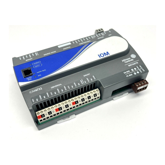
IOM4711 Input/Output Module Installation Instructions
MS-IOM4711-0U
Application
The IOM47 field controller is part of the Metasys® system
Field Equipment Controller family. Input/Output Module
(IOM) controller expand the number of points connected
to a Network Automation Engine (NAE), Field Equipment
Controller (FEC), or Advanced Application Field
Equipment Controller (FAC) to monitor and control a wide
variety of HVAC equipment.
IOM controllers operate on an RS-485 BACnet® MS/TP
Bus as BACnet Application Specific Controllers (B-ASCs)
and integrate into Johnson Controls® and third-party
BACnet systems.
Note: With CCT Release 10.3 and Release Module (RM)
10.2, a new capability allows VMAs, FECs, and
FACs to communicate by using either the BACnet
or the N2 field bus networking protocol. The I/O
can be connected through the SA bus to a host
controller that is using either the BACnet or the
N2 protocol. Only the BACnet protocol is
supported when the I/O is connected directly to
the trunk using the FC bus.
Important: The MS-IOM4711-0U model is used in
Metasys Release 8.1 smoke control
applications and is UL 864 UUKL/UUKLC
10th Edition Smoke Control Listed. You
must refer to the Metasys® System UL 864
10th Edition UUKL/ORD-C100-13 UUKLC
Smoke Control System Technical Bulletin
(LIT-12012487) for detailed requirements
and procedures for installing,
commissioning, and operating UL 864
UUKL/UUKLC Listed Metasys system
devices. The UL 864 UUKL/UUKLC listing
for Smoke Control Equipment is voided if
(1) you do not use the required software
tools at the required versions; or (2) you do
not meet the requirements or do not follow
the procedures as documented in the
Metasys® System UL 864 10th Edition
UUKL/ORD-C100-13 UUKLC Smoke
Control System Technical Bulletin
(LIT-12012487).
IOM4711 Input/Output Module Installation Instructions
Part No. 24-10144-211, Rev. A
North American Emissions
Compliance
Canada
This Class (A) digital apparatus meets all the
requirements of the Canadian Interference-Causing
Equipment Regulations.
Cet appareil numérique de la Classe (A) respecte toutes
les exigences du Règlement sur le matériel brouilleur
du Canada.
United States
This equipment has been tested and found to comply
with the limits for a Class A digital device pursuant to
Part 15 of the FCC Rules. These limits are designed to
provide reasonable protection against harmful
interference when this equipment is operated in a
commercial environment. This equipment generates,
uses, and can radiate radio frequency energy and, if not
installed and used in accordance with the instruction
manual, may cause harmful interference to radio
communications. Operation of this equipment in a
residential area may cause harmful interference, in which
case the users will be required to correct the interference
at their own expense.
Installation
Observe these guidelines when installing a controller:
•
Transport the controller in the original container to
minimize vibration and shock damage.
•
Verify that all parts shipped with the controller.
•
Do not drop the controller or subject it to physical
shock.
Parts Included
•
one controller with removable terminal blocks (Power
and SA/FC bus are removable)
•
one installation instructions sheet
Software Release 8.1
Issued March 2018
1
Advertisement
Table of Contents

Related Manuals for Johnson Controls IOM4711


Summary of Contents for Johnson Controls IOM4711
- Page 1 FC bus. installed and used in accordance with the instruction Important: The MS-IOM4711-0U model is used in manual, may cause harmful interference to radio Metasys Release 8.1 smoke control communications.
-
Page 2: Materials And Special Tools Needed
3. Drill holes in the wall or surface at the marked locations, and insert appropriate wall anchors in the holes (if necessary). IOM4711 Input/Output Module Installation Instructions... - Page 3 Device Address DIP Switch Block. (See Setting the Device Addresses.) Mounting Clip (One of Three) Configurable Output (CO) Terminal Blocks, 4 – Configurable Outputs. (See Table Analog Output (AO) Terminal Block, 2 – Analog Outputs. (See Table IOM4711 Input/Output Module Installation Instructions...
- Page 4 Note: The EOL Switch is located under the controller cover. You must remove the cover to change the EOL switch position. LED Status Indicators. (See Table Sensor Actuator (SA) Bus / Field Controller (FC) Bus Port (RJ-12 6-pin Modular Jack). (See SA/FC Bus Port.) BO Terminal Block, 3 – Binary Outputs. (See Table IOM4711 Input/Output Module Installation Instructions...
-
Page 5: Sa/Fc Bus Terminal Block
All of the input terminal blocks are mounted on the bottom of the controller and the output terminal blocks are mounted on the top of the controller. See Table 3 for more information about I/O terminal functions, requirements, and ratings. IOM4711 Input/Output Module Installation Instructions... -
Page 6: Supply Power Terminal Block
HOT and COM terminals on the terminal plug as shown in Figure 7. The middle terminal on the supply power terminal block is not used. See Table 5 for more information about the supply terminal block. IOM4711 Input/Output Module Installation Instructions... -
Page 7: Termination Details
Termination Details A set of Johnson Controls® termination diagrams provides details for wiring inputs and outputs to the controllers. See the figures in this section for the applicable termination diagrams. Table 2: Termination Details Type of Field Device Type of... - Page 8 Current Input - External Source (in Loop) Feedback from EPP-1000 Dry Contact (Binary Input) UI or BI 0–10 VDC Output to Actuator CO or AO (External Source) 0–10 VDC Output to Actuator CO or AO (Internal Source) IOM4711 Input/Output Module Installation Instructions...
- Page 9 Analog Output (Current) 24 VAC Triac Output (Switch CO or AO Low, External Source) Incremental Control to CO or AO Actuator (Switch Low, Externally Sourced) 24 VAC Triac Output (Switch CO or AO High, Externally Sourced) IOM4711 Input/Output Module Installation Instructions...
- Page 10 Actuator (Switch High, Externally Sourced) Incremental Control to Actuator (Switch Low, Externally Sourced) 24 VAC Binary Output (Switch Low, Externally Sourced) 24 VAC Binary Output (Switch High, Externally Sourced) Incremental Control to Actuator (Switch High, Externally Sourced) IOM4711 Input/Output Module Installation Instructions...
-
Page 11: Terminal Wiring Guidelines, Functions, Ratings, And Requirements
Cable runs over 30 m (100 ft) may require radio frequency noise. an offset in the input/output software setup. IOM4711 Input/Output Module Installation Instructions... - Page 12 Table Internal 12 V. 15k ohm pull up Qualified Sensors: 0-2k ohm potentiometer, RTD (1k Nickel [Johnson Controls® sensor], 1k Platinum, and A99B Silicon Temperature Sensor) Negative Temperature Coefficient (NTC) Sensor (10k Type L, 10k JCI Type II, 2.252k Type...
- Page 13 Jumper positioned to Connects OCOMn to 24~ when activated. Internal (INT) power. Internal Power Source: 30 VAC maximum output voltage 0.5 A maximum output current 1.3 A at 25% duty cycle 40 mA minimum load current IOM4711 Input/Output Module Installation Instructions...
- Page 14 Input common. Binary Output Signal Common All Configurable Outputs (COs) defined as Binary Outputs are isolated from all other commons, including other CO commons. Table 4 to determine wire size and cable lengths for cables. IOM4711 Input/Output Module Installation Instructions...
-
Page 15: Cable And Wire Length Guidelines
(in mA) when wiring inputs and outputs. Note: Figure 8 applies to low-voltage (<30 V) inputs and outputs only. Figure 8: Maximum Wire Length for Low-Voltage (<30V) Inputs and Outputs by Current and Wire Size IOM4711 Input/Output Module Installation Instructions... -
Page 16: Sa/Fc Bus And Supply Power Wiring Guidelines
The SA Bus and FC Bus wiring recommendations in this table are for MS/TP bus communications at 38,400 baud. For more information, refer to the MS/TP Communications Bus Technical Bulletin (LIT-12011034). IOM4711 Input/Output Module Installation Instructions... -
Page 17: Setup And Adjustments
ON and a device address from 4 to 127 is connected to a wired field bus, the entire field bus is rendered inoperable until the controller is disconnected or switch 128 is set to Off. IOM4711 Input/Output Module Installation Instructions... -
Page 18: Input/Output Jumper Settings
To set the EOL switch on a controller: 1. Determine the physical location of the controller on the SA or FC bus. 2. Determine if the controller must be set as a terminating device on the bus. IOM4711 Input/Output Module Installation Instructions... -
Page 19: Ui Current Loop Jumpers
You commission IOM controllers with the Controller Figure 13: Current Loop Jumper Positions Configuration Tool (CCT) software. Refer to the Controller Tool Help (LIT-12011147) for detailed information on commissioning controllers. IOM4711 Input/Output Module Installation Instructions... -
Page 20: Troubleshooting The Controllers
Off Steady = EOL switch in Off position devices) Repair Information The MS-IOM4711-0U model is UL 864 10th Edition UUKL/ORD-C100-13 UUKLC listed for smoke control. If a controller fails to operate within its specifications, contact the Johnson Controls Repair Center in Louisville, Kentucky, at 1-502-671-7312. - Page 21 The performance specifications are nominal and conform to acceptable industry standard. For application at conditions beyond these specifications, consult the local Johnson Controls® office. Johnson Controls shall not be liable for damages resulting from misapplication or misuse of its products.
- Page 22 Building Technologies & Solutions 507 E. Michigan Street, Milwaukee, WI 53202 Johnson Controls® is a registered trademark of Johnson Controls. All other marks herein are the marks of their respective owners.© 2018 Johnson Controls Published in U.S.A. www.johnsoncontrols.com IOM4711 Input/Output Module Installation Instructions...