Table of Contents
Advertisement
Quick Links
IOM3721 Input/Output Module Installation Instructions
MS-IOM3721
Application
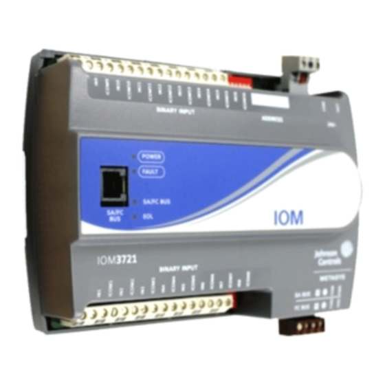
The IOM3721 field controller is a part of the Metasys®
system Field Equipment Controller family. Input/Output
Module (IOM) field controllers expand the number of
points connected to an Network Automation Engine
(NAE), Network Control Engine (NCE), Field Equipment
Controller (FEC), or Advanced Application Field
Equipment Controller (FAC) to monitor and control a wide
variety of Heating, Ventilating, and Air Conditioning
(HVAC) equipment.
IOM field controllers operate on an RS-485 BACnet®
Master-Slave/Token-Passing (MS/TP) Bus as BACnet
Application Specific Controllers (B-ASCs) and integrate
into the Web-based Metasys system.
Important: In Metasys system smoke control
applications, use only the MS-IOM3710-0U
models that are UL Listed, UUKL/UUKLC
864 Listed, Smoke Control Equipment. For
Metasys system smoke control applications,
you must refer to the Metasys System UL
864 Ninth Edition UUKL/UUKL7 Smoke
Control System Technical Bulletin
(LIT-12011252) for detailed requirements
and procedures for installing and operating
UUKL/UUKLC 864 Listed Metasys system
devices. Failure to meet the requirements
or follow the procedures in the Metasys
System UL 864 Ninth Edition UUKL/UUKL7
Smoke Control System Technical Bulletin
(LIT-12011252) can void the UUKL/UUKLC
864 listing for Smoke Control Equipment.
North American Emissions
Compliance
Canada
This Class (A) digital apparatus meets all the requirements
of the Canadian Interference-Causing Equipment
Regulations. Cet appareil numérique de la Classe (A)
respecte toutes les exigences du Règlement sur le matériel
brouilleur du Canada.
IOM3721 Input/Output Module Installation Instructions
Part No. 24-10144-130, Rev. D
Refer to the
QuickLIT Web site
United States
This equipment has been tested and found to comply with
the limits for a Class A digital device pursuant to Part 15
of the FCC Rules. These limits are designed to provide
reasonable protection against harmful interference when
this equipment is operated in a commercial environment.
This equipment generates, uses, and can radiate radio
frequency energy and, if not installed and used in
accordance with the instruction manual, may cause
harmful interference to radio communications. Operation
of this equipment in a residential area is likely to cause
harmful interference, in which case the user will be
required to correct the interference at his/her own
expense.
Installation
Observe these guidelines when installing a field controller:
•
Transport the controller in the original container to
minimize vibration and shock damage.
•
Verify that all parts shipped with the controller.
•
Do not drop the controller or subject it to physical
shock.
Parts Included
•
one field controller with removable terminal blocks
(Power, SA, and FC bus are removable)
•
one installation instructions sheet
Materials and Special Tools Needed
•
three fasteners appropriate for the mounting surface
(M4 screws or #8 screws)
•
one 20 cm (8 in.) or longer piece of 35 mm DIN rail
and appropriate hardware for DIN rail mount (only)
•
small straight blade screwdriver for securing wires in
the terminal blocks
Mounting
Observe these guidelines when mounting a field
controller:
•
Ensure the mounting surface can support the
controller, DIN rail, and any user-supplied enclosure.
•
Mount the controller horizontally on 35 mm DIN rail
whenever possible.
•
Mount the controller in the proper mounting position
(Figure
1).
Software Release 6.0
Issued January 30, 2013
Supersedes May 25, 2012
for the most up-to-date version of this document.
1
Advertisement
Table of Contents

Related Manuals for Johnson Controls IOM3721


Summary of Contents for Johnson Controls IOM3721
- Page 1 Application United States The IOM3721 field controller is a part of the Metasys® system Field Equipment Controller family. Input/Output This equipment has been tested and found to comply with the limits for a Class A digital device pursuant to Part 15 Module (IOM) field controllers expand the number of of the FCC Rules.
-
Page 2: Wall Mount Applications
1. Securely mount a 20 cm (8 in.) or longer section of 35 mm DIN rail horizontal and centered in the desired space so that the controller mounts in the horizontal position shown in Figure IOM3721 Input/Output Module Installation Instructions... - Page 3 Figure 3: IOM3721 Physical Features Table 1: IOM3721 Feature Callout Numbers and Descriptions Callout Physical Feature: Description and References Device Address DIP Switch Block (See Setting the Device Addresses) 24 VAC, Class 2 Supply Power Terminal Blocks (See Supply Power Terminal...
- Page 4 An IOM can be connected to a Sensor/Actuator (SA) bus or a Field Controller (FC) bus, but not to both buses simultaneously. The SA/FC bus terminal block is a removable, 4-terminal plug that fits into a board-mounted jack. IOM3721 Input/Output Module Installation Instructions...
-
Page 5: Wireless Network Applications
3. Set DIP switch 128 to ON, which enables wireless operation on the field controller. For more information on installing a controller in a wireless configuration, refer to the ZFR1811 Wireless Field Bus Router Installation Instructions (Part No. 24-10325-1). IOM3721 Input/Output Module Installation Instructions... -
Page 6: Terminal Wiring Guidelines, Functions, Ratings, And Requirements
Cable runs over 30 m (100 ft) may require an offset in the input/output software setup. Table 2: IOM3721 Terminal Blocks, Functions, Ratings, Requirements, and Cables Terminal Block Terminal Function, Ratings, Requirements... -
Page 7: Cable And Wire Length Guidelines
(in mA) when wiring inputs and outputs. Figure 8: Maximum Wire Length for Low-Voltage (<30V) Inputs and Outputs by Current and Wire Size IOM3721 Input/Output Module Installation Instructions... -
Page 8: Sa/Fc Bus And Supply Power Wiring Guidelines
2 The SA Bus and FC Bus wiring recommendations in this table are for MS/TP bus communications at 38400 baud. For more information, refer to the MS/TP Communications Bus Technical Bulletin (LIT-12011034). IOM3721 Input/Output Module Installation Instructions... -
Page 9: Setup And Adjustments
21, set switch 16 to ON first, then set switch 4 ON, followed by switch 1 (16+4+1= 21). 3. Set switch 128 to ON only for controllers on a ZFR1800 Series Wireless Field Bus application. For IOM3721 Input/Output Module Installation Instructions... -
Page 10: Removing The Controller Cover
DIS1710 Local Controller Display Technical 3. Replace the cover by placing it squarely over the Bulletin (LIT-12011270). base, and then gently and evenly push the cover on to the latches until they snap into the latched position. IOM3721 Input/Output Module Installation Instructions... -
Page 11: Repair Information
Advance Order Management System (AOMS). For additional information on the ZFR-USBHA-0 ZigBee dongle, refer to the ZFR1800 Series Wireless Field Bus System Technical Bulletin (LIT-12011295) or ZFR1800 Series Wireless Field Bus System Quick Reference Guide (LIT-12011630). IOM3721 Input/Output Module Installation Instructions... -
Page 12: Technical Specifications
Canada: UL Listed, File E107041, CCN PAZX7 CAN/CSA C22.2 No.205, Signal Equipment Industry Canada Compliant, ICES-003 Europe: Johnson Controls, Inc., declares that this product is in compliance with the essential requirements and other relevant provisions of the EMC Directive 2004/108/EC. - Page 13 The performance specifications are nominal and conform to acceptable industry standard. For application at conditions beyond these specifications, consult the local Johnson Controls® office. Johnson Controls, Inc. shall not be liable for damages resulting from misapplication or misuse of its products.