Table of Contents
Advertisement
Quick Links
IOM4710 Input/Output Module
Installation Instructions
MS-IOM4710-0
Applications
The Input/Output Module (IOM) 4710 is a member of
the Metasys® system Field Equipment Controller
(FEC) family. The IOM controller provides increased
capacity to larger FEC applications when used on the
Sensor Actuator (SA) Bus. The IOM controller can also
be used on the Field Controller (FC) Bus to connect
additional I/O points to the system.
The IOM4710 controller (MS-IOU4710-0) comprises
two parts: the mounting base (MS-IOB4710-0) and the
module cover (MS-IOM4710-0).
IMPORTANT: In Metasys system smoke control
applications, use only the IOM4710 models that are
UL Listed, UUKL 864 Listed, Smoke Control
Equipment. See Repair Information on page 10 for
UUKL 864 Listed IOM4710 models. For Metasys
system smoke control applications, you must refer to
the Metasys System UL 864 UUKL Ninth Edition
Smoke Control System Technical Bulletin
(LIT-12011252) for detailed requirements and
procedures for installing and operating UUKL 864
Listed Metasys system devices. Failure to meet the
requirements or follow the procedures in the
Metasys System UL 864 UUKL Ninth Edition Smoke
Control System Technical Bulletin (LIT-12011252)
can void the UUKL 864 listing for Smoke Control
Equipment.
North American Emissions Compliance
Canada
This Class (A) digital apparatus meets all the
requirements of the Canadian Interference-Causing
Equipment Regulations.
Cet appareil numérique de la Classe (A) respecte
toutes les exigences du Règlement sur le matériel
brouilleur du Canada.
United States
This equipment has been tested and found to
comply with the limits for a Class A digital device
pursuant to Part 15 of the FCC Rules. These limits
are designed to provide reasonable protection
against harmful interference when this equipment is
operated in a commercial environment. This
equipment generates, uses, and can radiate radio
frequency energy and, if not installed and used in
accordance with the instruction manual, may cause
harmful interference to radio communications.
Operation of this equipment in a residential area is
likely to cause harmful interference, in which case
the user will be required to correct the interference
at his/her own expense.
Installation
Observe the following guidelines when installing the
IOM controller:
•
Transport the IOM controller in the original
container to minimize vibration and shock damage
to the IOM.
•
Do not drop the IOM controller or subject it to
physical shock.
Materials and Special Tools Needed
You need either of the following items to install the IOM
controller:
•
three fasteners appropriate for the mounting
surface (#8 screws or M4 screws)
•
one 20.3 cm (8 in.) or longer piece of DIN rail and
appropriate hardware for mounting the DIN rail
Mounting
Follow these guidelines when mounting an IOM
controller:
•
Ensure that the mounting surface can support the
IOM controller and any user supplied enclosure.
•
Mount the IOM controller in the proper orientation.
See the Wall Mount Applications and DIN Rail
Mount Applications section.
IOM4710 Input/Output Module Installation Instructions
Part No. 24-10144-25, Rev. H
Release 5.0
Issued January 4, 2010
Supersedes October 6, 2008
1
Advertisement
Table of Contents

Related Manuals for Johnson Controls IOM4710


Summary of Contents for Johnson Controls IOM4710
- Page 1 Operation of this equipment in a residential area is IMPORTANT: In Metasys system smoke control likely to cause harmful interference, in which case applications, use only the IOM4710 models that are the user will be required to correct the interference UL Listed, UUKL 864 Listed, Smoke Control at his/her own expense.
-
Page 2: Wall Mount Applications
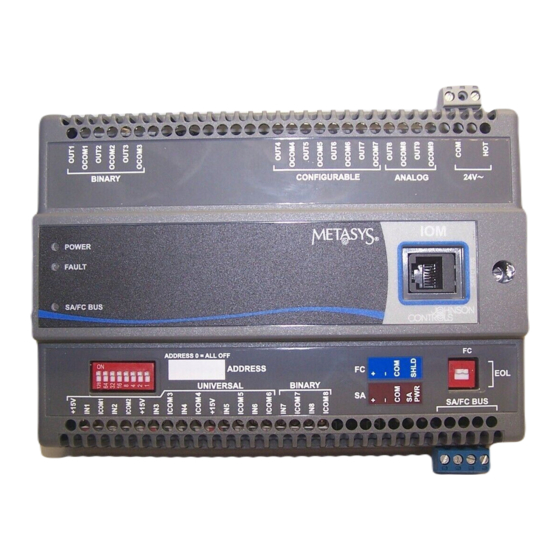
Universal Binary Terminals Inputs Inputs Figure 1: IOM4710 Controller Physical Features and Wiring Terminals Wall Mount Applications To mount the IOM controller on a wall or other vertical surface: Use the holes in the mounting clips for wall mount applications. -
Page 3: Din Rail Mount Applications
(in Extended Positions) To remove the IOM controller from the DIN rail, snap the bottom DIN clips to the outboard position and Figure 2: IOM4710 Controller Mounting Features, carefully lift the IOM controller off the DIN rail. mm (in.) 2. Mark the location of the wall mount holes using the dimensions in Figure 3, or hold the IOM controller up to the wall as a template and mark the locations. - Page 4 Wireless Commissioning Converter. Engine (NCE), wire the FC Bus in a daisy chain See Table 1 for more information. The SA/FC Bus Port (Figure 6). pin assignment is shown in (Figure 8). IOM4710 Input/Output Module Installation Instructions...
- Page 5 Analog Input, Resistive Mode Accepts 0-600k ohm input signal. Internal 12 V, 15k ohm Pullup RTD (1k Nickel [Johnson Controls], 1k Platinum, A99B Silicon Temperature Sensor) Negative Temperature Coefficient (NTC) Sensor (10k Type L, 2.252k Type 2) Binary Input, Dry Contact Maintained Mode 1 s minimum pulse width (0.5 Hz at 50% duty cycle)
- Page 6 Sources 24~ Power (Hot) (Jumper Set OCOM n Binary Output, 24 VAC Triac to Internal) Connects OCOM to 24~ Power (Com) when activated. 30 VAC maximum output voltage 0.5 A maximum output current 40 mA minimum load current IOM4710 Input/Output Module Installation Instructions...
- Page 7 The SA Bus and the SA/FC Bus Port are daisy-chained internally. The SA Bus and FC Bus specifications in this table are for MS/TP bus communications at 38.4k baud. For more information, refer to the MS/TP Communications Bus Technical Bulletin (LIT-12011034). IOM4710 Input/Output Module Installation Instructions...
-
Page 8: Setup And Adjustments
IOM to the FC Bus or SA Bus. For more information, wireless operation. refer to the MS/TP Communications Bus Technical 129-255 Are not valid addresses for FEC or IOM Bulletin (LIT-12011034). controllers on the SA or FC Bus. IOM4710 Input/Output Module Installation Instructions... -
Page 9: Setting The Jumpers
Binary Output terminals. Failure to follow this precaution may cause damage to the Note: This jumper must be in the DISABLE position controller. for all Universal Input modes other than 4-20 mA. IOM4710 Input/Output Module Installation Instructions... -
Page 10: Troubleshooting
4. Install a new replacement fuse. specifications, replace the unit. For a replacement IOM 5. Replace the cover. See Attaching the Cover. controller, contact the nearest Johnson Controls® representative. 6. Reconnect power to the controller. Table 4: Status Light-Emitting Diodes (LEDs) -
Page 11: Technical Specifications
The performance specifications are nominal and conform to acceptable industry standard. For application at conditions beyond these specifications, consult the local Johnson Controls office. Johnson Controls, Inc. shall not be liable for damages resulting from misapplication or misuse of its products. - Page 12 507 E. Michigan Street, Milwaukee, WI 53202 Metasys® and Johnson Controls® are registered trademarks of Johnson Controls, Inc. All other marks herein are the marks of their respective owners. © 2010 Johnson Controls, Inc. IOM4710 Input/Output Module Installation Instructions Published in U.S.A.