Table of Contents
Advertisement
Quick Links
Application
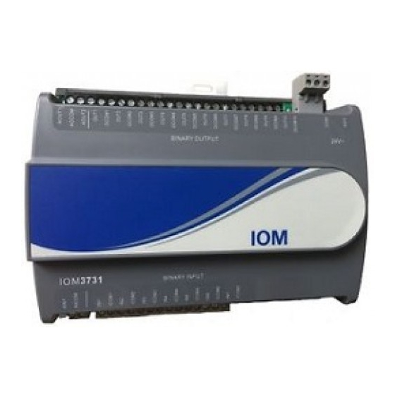
The IOM3731-0A expansion module is part of the
Metasys
system Field Equipment Controller family.
®
Input/Output expansion modules (IOMs) expand the
number of input/output points connected to either a
Network Automation Engine (NAE), Network Control
Engine (NCE), Advanced Application Field Equipment
Controller (FAC), Field Equipment Controller (FEC),
or Variable Air Volume Modular Assembly (VMA)
to monitor and control a wide variety of HVAC
equipment.
IOM expansion modules operate on an RS-485
BACnet
MS/TP bus and integrate into Johnson
®
Controls and third-party BACnet systems. IOMs
communicate using the BACnet MS/TP protocol
when directly connected to the FC bus.
Note: With Release 10.1 and later of the
Controller Configuration Tool (CCT), VMAs, FECs,
and FACs can be configured to communicate
by using either the BACnet MS/TP or the N2
field bus networking protocol. The operation of
the IOM is not affected by the selection of the
BACnet MS/TP or the N2 protocol in the host
controller, when the IOM is connected to the
host controller using the SA bus.
North American emissions
compliance
United States
This equipment has been tested and found to
comply with the limits for a Class A digital device
pursuant to Part 15 of the FCC Rules. These limits
are designed to provide reasonable protection
against harmful interference when this equipment
is operated in a commercial environment. This
equipment generates, uses, and can radiate radio
frequency energy and, if not installed and used in
accordance with the instruction manual, may cause
harmful interference to radio communications.
Operation of this equipment in a residential area
may cause harmful interference, in which case the
users will be required to correct the interference at
their own expense.
IOM3731-0A Expansion Input/Output Installation
Canada
This Class (A) digital apparatus meets all the
requirements of the Canadian Interference-Causing
Equipment Regulations.
Cet appareil numérique de la Classe (A) respecte
toutes les exigences du Règlement sur le matériel
brouilleur du Canada.
Installation
Observe these guidelines when installing an
expansion module:
• Transport the expansion module in the original
container to minimize vibration and shock
damage.
• Verify that all parts shipped with the expansion
module.
• Do not drop the expansion module or subject it to
physical shock.
Parts included
• One expansion module with removable terminal
blocks (Power and SA/FC bus are removable)
• One installation instructions sheet
Materials and special tools needed
• Three fasteners appropriate for the mounting
surface (M4 screws or #8 screws)
• One 20 cm (8 in.) or longer piece of 35 mm DIN
rail and appropriate hardware for DIN rail mount
(only)
• Small straight-blade screwdriver for securing
wires in the terminal blocks
Guide
Part No. 24-10144-165 Rev. J
2019-10-18
*2410144165J*
(barcode for factory use only)
MS-IOM3731-0A
Advertisement
Table of Contents

Related Manuals for Johnson Controls IOM3731-0A


Summary of Contents for Johnson Controls IOM3731-0A
- Page 1 Guide Part No. 24-10144-165 Rev. J 2019-10-18 Application Canada This Class (A) digital apparatus meets all the The IOM3731-0A expansion module is part of the requirements of the Canadian Interference-Causing Metasys system Field Equipment Controller family. ® Equipment Regulations. Input/Output expansion modules (IOMs) expand the number of input/output points connected to either a Cet appareil numérique de la Classe (A) respecte...
-
Page 2: Physical Features
The following figure displays the physical features of the IOM, and the accompanying table provides a Figure 1: IOM3731-0A physical features Table 1: IOM3731-0A feature callouts and • Mount the expansion module in the proper mounting position (Figure 2). descriptions Callo •... -
Page 3: Wall-Mount Applications
Push the bottom mounting clips inward (up) to secure the controller on the DIN rail. To remove the controller from the DIN rail, pull the bottom mounting clips out to the extended position and carefully lift the controller off the DIN rail. IOM3731-0A Expansion Input/Output Installation Guide... -
Page 4: Terminal Blocks And Bus Ports
Important: Do not exceed the controller electrical ratings. Exceeding controller electrical ratings can result in permanent damage to the controller and void any warranty. Important: Use copper conductors only. Make all wiring in accordance with local, national, and regional regulations. IOM3731-0A Expansion Input/Output Installation Guide... -
Page 5: Sa/Fc Bus Port
The SA/FC bus port pin assignment is shown in Figure 6. Note: The supply power wire colors may be different on transformers from other manufacturers. Refer to the transformer manufacturer’s instructions and the project installation drawings for wiring details. IOM3731-0A Expansion Input/Output Installation Guide... -
Page 6: Wireless Network Applications
Input and output wiring guidelines The following table provides information and guidelines about the functions, ratings, and requirements for the controller input and output terminals; and references guidelines for determining proper wire sizes and cable lengths. IOM3731-0A Expansion Input/Output Installation Guide... - Page 7 I/O terminal blocks, ratings, and requirements table Table 2: IOM3731-0A terminal blocks, functions, ratings, requirements, and cables Terminal Determine wire size and Terminal block label Function, ratings, requirements label maximum cable length Binary Input - Dry Contact Maintained Mode 0.01 second minimum pulse width...
- Page 8 15 VDC to devices on the SA Bus requiring power. 24 VAC Power Supply - Hot 0.8 mm to 1.0 mm Supplies 20-30 VAC (Nominal 24 VAC) (18 AWG) 2-wire 24 VAC Power Supply - Common IOM3731-0A Expansion Input/Output Installation Guide...
-
Page 9: Termination Details
Termination details controllers. See the figures in this section for the applicable termination diagrams. A set of Johnson Controls termination diagrams provides details for wiring inputs and outputs to the Table 5: Termination details Type of device Type of Input/Output... -
Page 10: Setup And Adjustments
Figure 9: Device address DIP switch block set to on the expansion module's cover. address 21 The following table describes the FC bus and SA bus device addresses for Johnson Controls MS/TP com- munications bus applications. Table 6: SA/FC bus device address descriptions Device Address Use on Descriptions... -
Page 11: Troubleshooting
Blink - 2 Hz = Data Transmission (normal communication) SA/FC BUS Green Blink - 2 Hz Off Steady = No Data Transmission (N/A - auto baud not supported) On Steady = Communication lost; waiting to join communication ring IOM3731-0A Expansion Input/Output Installation Guide... -
Page 12: Repair Information
Refer to the NS Series Network Sensors Product Bulletin (LIT-12011574) for specific sensor model NS Series Network Sensors descriptions. WRZ Series Wireless Room Refer to the WRZ Series Wireless Room Sensors Product Bulletin (LIT-12000653) for specific sensor model Sensors descriptions. IOM3731-0A Expansion Input/Output Installation Guide... -
Page 13: Technical Specifications
Canada: UL Listed, File E107041, CCN PAZX7 CAN/CSA C22.2 No. 205, Signal Equipment Industry Canada Compliant, ICES-003 Europe: Johnson Controls declares that this product is in compliance with the essential requirements and other relevant provisions of the EMC Directive. Australia and New Zealand: RCM Mark, Australia/NZ Emissions Compliant... - Page 14 DISTRICT WUXI JIANGSU PROVINCE 214028 CHINA For more contact information, refer to www.johnsoncontrols.com/locations. © 2019 Johnson Controls. All rights reserved. All specifications and other information shown were current as of document revision and are subject to change without notice. www.johnsoncontrols.com...