Table of Contents
Advertisement
Quick Links
Application
The IOM3721 input/output expansion module is
a part of the Metasys
®
Controller family. Input/Output expansion modules
(IOMs) expand the number of input/output points
connected to a Network Automation Engine (NAE),
Network Control Engine (NCE), Advanced Application
Field Equipment Controller (FAC), Field Equipment
Controller (FEC), or Variable Air Volume Modular
Assembly (VMA) to monitor and control a wide
variety of HVAC equipment.
IOM expansion modules operate on an RS-485
BACnet
MS/TP Bus and integrate into Johnson
®
Controls
and third-party BACnet systems. IOMs
®
Note: With Release 10.1 of the Controller
Configuration Tool (CCT), VMAs, FECs, and
FACs can be configured to communicate using
either the BACnet MS/TP or the N2 field bus
networking protocol. The operation of the
IOM is not affected by the selection of the
BACnet MS/TP or the N2 protocol in the host
controller, when the IOM is connected to the
host controller using the SA bus.
North American emissions
compliance
United States
This equipment has been tested and found to
comply with the limits for a Class A digital device
pursuant to Part 15 of the FCC Rules. These limits
are designed to provide reasonable protection
against harmful interference when this equipment
is operated in a commercial environment. This
equipment generates, uses, and can radiate radio
frequency energy and, if not installed and used in
accordance with the instruction manual, may cause
harmful interference to radio communications.
Operation of this equipment in a residential area
may cause harmful interference, in which case the
users will be required to correct the interference at
their own expense.
IOM3721 Expansion Input/Output Module
system Field Equipment
Installation Guide
Canada
This Class (A) digital apparatus meets all the
requirements of the Canadian Interference-Causing
Equipment Regulations.
Cet appareil numérique de la Classe (A) respecte
toutes les exigences du Règlement sur le matériel
brouilleur du Canada.
Installation
Observe the following guidelines when installing an
expansion module:
• To minimize vibration and shock damage,
transport the expansion module in the original
container.
• Verify that all parts shipped with the expansion
module.
• Do not drop the expansion module or subject it to
physical shock.
Parts included
• One expansion module with removable terminal
blocks (Power and SA/FC bus are removable)
• One installation instructions sheet
Materials and special tools needed
• Three fasteners appropriate for the mounting
surface (M4 screws or #8 screws)
• One 20 cm (8 in.) or longer piece of 35 mm DIN
rail and appropriate hardware for DIN rail mount
• Small straight-blade screwdriver for securing
wires in the terminal blocks
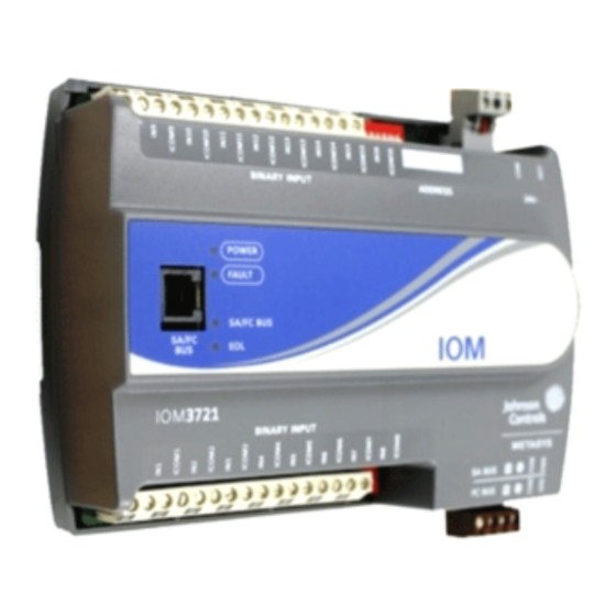
Physical features
The following figure displays the physical features
of an IOM, and the accompanying table provides a
description of the physical features and a reference
to further information where required.
Part No. 24-10144-130 Rev. K
2019-10-18
*2410144130K*
(barcode for factory use only)
MS-IOM3721
Advertisement
Table of Contents

Related Manuals for Johnson Controls IOM3721


Summary of Contents for Johnson Controls IOM3721
- Page 1 Installation Guide Part No. 24-10144-130 Rev. K 2019-10-18 Application Canada This Class (A) digital apparatus meets all the The IOM3721 input/output expansion module is requirements of the Canadian Interference-Causing a part of the Metasys system Field Equipment ® Equipment Regulations.
- Page 2 Figure 1: IOM3721 physical features Table 1: IOM3721 feature callout numbers and • Mount the expansion module in the proper mounting position (Figure 2). descriptions Callo • Mount the expansion module on a hard, even Physical feature: description and references surface whenever possible in wall-mount...
-
Page 3: Wall Mount Applications
DIN rail. Push the bottom mounting clips inward (up) to secure the expansion module on the DIN rail. To remove the expansion module from the DIN rail, pull the bottom mounting clips IOM3721 Expansion Input/Output Module Installation Guide... -
Page 4: Terminal Blocks And Bus Ports
électrique et de provoquer des blessures graves, voire mortelles. Input terminal blocks The IOM3721 has inputs only (no outputs). The inputs are located on both the top and bottom of the expansion module. See Table 4 for more information about I/O terminal functions, requirements, and ratings. - Page 5 Wire the 24 VAC supply power wires from the transformer to the HOT and COM terminals on the terminal plug as shown in Figure 7. The middle terminal on the supply power terminal block is not used. IOM3721 Expansion Input/Output Module Installation Guide...
-
Page 6: Wireless Network Applications
0.5 mm (24 AWG) stranded copper 61 m (200 ft) twisted wire point. See Figure 8 to determine See Figure 8 to select wire size/gauge. Use cable length. Use twisted stranded copper wire. wire cable. IOM3721 Expansion Input/Output Module Installation Guide... - Page 7 SA/FC BUS Common retractable cable or 24 AWG 3-pair CAT 3 (Port) Commissioning Converter or ZFR /ZFR Pro Cable <30.5 m (100 ft) Wireless Router (Maximum total current draw for SA Bus is 100 mA.) IOM3721 Expansion Input/Output Module Installation Guide...
- Page 8 • Inputs/outputs with cables less than 30 m (100 ft) typically do not require an offset in the software setup. Cable runs over 30 m (100 ft) may require an offset in the input/output software setup. IOM3721 Expansion Input/Output Module Installation Guide...
-
Page 9: Termination Details
I/O terminal blocks, ratings, and requirements Table 4: IOM3721 terminal blocks, functions, ratings, requirements, and cables Terminal block Determine wire size and Terminal label Function, ratings, requirements label maximum cable length Binary Input - Dry Contact Maintained Mode 0.01 second minimum pulse width Internal 16 V, 10K ohm pull Binary Input - Pulse Counter/Accumulator Mode 0.01 second minimum pulse width... -
Page 10: Setting The End-Of-Line (Eol) Switch
Controls MS/TP communications bus appli- cations. Each expansion module has an EOL switch, which when set to ON, sets the expansion module as a terminating device on the bus. See Figure 1 for the IOM3721 Expansion Input/Output Module Installation Guide... - Page 11 Off Steady = No Data Transmission (N/A - auto baud not supported) On Steady = Communication lost, waiting to join communication ring Off (Except on On Steady = EOL switch in ON position Amber terminating Off Steady = EOL switch in Off position devices) IOM3721 Expansion Input/Output Module Installation Guide...
-
Page 12: Repair Information
Refer to the WRZ Series Wireless Room Sensors Product Bulletin (LIT-12000653) for specific sensor model Room Sensors descriptions. Mobile Access Portal Refer to the Mobile Access Portal Gateway Catalog Page (LIT-1900869) to identify the appropriate product for (MAP)Gateway your region. IOM3721 Expansion Input/Output Module Installation Guide... -
Page 13: Technical Specifications
The performance specifications are nominal and conform to acceptable industry standard. For application at conditions beyond these specifications, consult the local Johnson Controls office. Johnson Controls shall not be liable for damages resulting from misapplication or misuse of its products. - Page 14 MILWAUKEE WI 53202 NO. 32 CHANGJIJANG RD NEW GERMANY DISTRICT WUXI JIANGSU PROVINCE 214028 CHINA © 2019 Johnson Controls. All rights reserved. All specifications and other information shown were current as of document revision and are subject to change without notice. www.johnsoncontrols.com...