Table of Contents
Advertisement
Quick Links
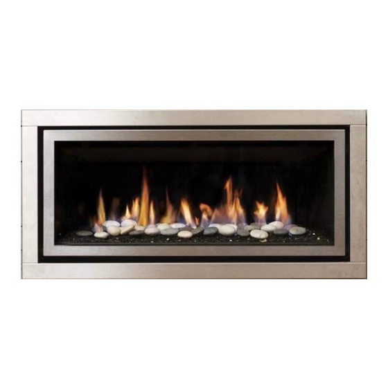
Greenfire
Gas Fireplace
www.regency-fire.com.au
WARNING:
If the information in these instructions are not followed exactly,
a fire or explosion may result causing property damage,
personal injury or loss of life.
FOR YOUR SAFETY
Do not store or use gasoline or other flammable vapors and
liquids in the vicinity of this or any other appliance.
Installation and service must be performed by a qualified
installer, service agency or the gas supplier.
Installer: Please complete the details on the back cover and leave this manual with the homeowner.
Homeowner: Please keep these instructions for future reference.
920-038c
GF900C
®
Owners &
Installation Manual
MODELS: GF900C-NG2
GF900C-LP2
GF900C-ULPG2
GF900C Video
LISTINGS AND CODE APPROVALS
These gas appliances have been tested in
accordance with AS/NZS 5263.0, AS/NZS
5263.1.3 and have been certified by the
Australian Gas Association for installation
and operation as described in these
Installation and Operating Instructions.
Must be installed as per AS/NZS5601
Your unit should be serviced annually
by an authorised service person.
FOR YOUR SAFETY
What to do if you smell gas:
Do not try to light any appliance
Do not touch any electrical switch:
do not use any phone in your
building.
Immediately call your gas supplier
from a neighbour's phone. Follow
the gas supplier's instructions.
If you cannot reach your gas
supplier, call the fire department.
02.28.22
Advertisement
Table of Contents

Related Manuals for Regency Fireplace Products Greenfire GF900C-NG2


Summary of Contents for Regency Fireplace Products Greenfire GF900C-NG2
- Page 1 Greenfire GF900C ® Owners & Installation Manual Gas Fireplace MODELS: GF900C-NG2 GF900C-LP2 GF900C-ULPG2 GF900C Video LISTINGS AND CODE APPROVALS These gas appliances have been tested in accordance with AS/NZS 5263.0, AS/NZS 5263.1.3 and have been certified by the Australian Gas Association for installation and operation as described in these Installation and Operating Instructions.
- Page 2 PAIRING YOUR REMOTE CONTROL The control box will only learn the Remote ID codes during the first 30 seconds after power is applied and will ignore this special command from the Remote after the first 30 seconds. To the New Owner: To match the control box to the remote, follow the steps below : Congratulations! You are the owner of a state-of-the-art Gas Fireplace by REGENCY...
- Page 3 WARNING DO NOT turn your fireplace on via any means or allow to be turned on unless you have conducted a thourough inspection of the area sur- rounding the fireplace immediately prior to its use, and you have satisfied yourself that there are no materials or other items in proximity to the fireplace which could present a fire risk.
-
Page 4: Table Of Contents
table of contents Pairing the Remote Handset and Control Box ID Code .2 Unit Installation with Vertical Termination ....34 Copy of data badge ............5 System Data ..............35 Unit Dimensions ............6 High Elevation ..............35 Verona Surround Faceplate Dimensions .......6 Gas Line Installation ............35 Important Message ............7 Pilot Adjustment ............35 General Safety Information ..........7... -
Page 5: Copy Of Data Badge
safety decal This is a copy of the data badge that accompanies each GF900 Direct Flue Gas Fireplace. We have printed a copy of the contents here for your review. NOTE: Regency ® units are constantly being improved. Check the badge on the unit and if there is a difference, the badge on the unit is the correct one. COPY OF DATA BADGE Regency Gas Fireplace Model... -
Page 6: Unit Dimensions
DIMENSIONS dimensions UNIT DIMENSIONS 500mm 1091mm 560mm 996mm 523mm 14mm 890mm (1192mm) (989mm) Verona Surround Faceplate Dimensions Regency GF900C-2 Gas Fireplace... -
Page 7: Important Message
installation IMPORTANT MESSAGE 11) Under no circumstances should this appliance YOUNG CHILDREN SHOULD BE be modified. Parts that have to be removed SAVE THESE CAREFULLY SUPERVISED WHEN for servicing should be replaced prior to INSTRUCTIONS THEY ARE IN THE SAME AREA AS operating this appliance. -
Page 8: Installation Checklist
installation INSTALLATION CHECKLIST This includes: 4) The GF900 Direct Flue Gas Fireplace 1) Clocking the appliance to ensure the correct is approved for alcove installations, see 1) Locate appliance firing rate (rate noted on label) after burning "Clearances" section for details. a) Room location (Refer to "Locating Your appliance for 15 minutes. -
Page 9: Clearances
installation CLEARANCES The clearances listed below are Minimum distances unless otherwise stated: A major cause of chimney related fires is failure to maintain required clearances (air space) to combustible materials. It is of the greatest importance that this fireplace and vent system be installed only in accordance with these instructions. Caution Requirements WARNING Fire hazard is an extreme risk... -
Page 10: Framing Dimensions
installation FRAMING DIMENSIONS IMPORTANT NOTE: Framing Description GF900C This unit can be finished Dimensions with combustible facing Framing Height 940mm combustible finish material of thickness range ¹ Framing Height -Steel Stud 756mm non combustible steel stud 10-19mm OR non-combus- Framing Width 1127mm tible facing material of a Framing Depth... -
Page 11: Combustible Finishing
installation COMBUSTIBLE FINISHING UNIT ASSEMBLY/ FINISHING/ MANTEL CLEARANCES + MANTEL LEG CLEARANCES UNIT ASSEMBLY PRIOR TO INSTALLATION The nailing strips must be correctly positioned and attached before unit is slid into position. NAILING STRIPS-COMBUSTIBLE FINISHING The nailing strips come attached to the unit. There is 1 plate on each side, 1 on the top. -
Page 12: Framing & Finishing (Combustible)
installation FRAMING & FINISHING (COMBUSTIBLE) Note: Finished *Finishing Trim or one of the fascias must be used with com- Material bustible finishing. 10mm to 19mm combustible finishing can be used if the 13mm 1st slot 0mm-19mm thick- air gap around the front facing of the unit is maintained. Finishing ness using combus- material cannot be thicker than 19mm and must be flush with the tible finishing... -
Page 13: Clearances For Combustible Finishing With Mantel
installation CLEARANCES FOR COMBUSTIBLE FINISHING WITH MANTEL Due to the extreme heat this fireplace emits, the mantel clearances are critical. Combustible finishing and mantel clearances are shown in the diagram on the right. Finishing Trim must be used with combustible finishing. (305mm) (152mm) Note: Maximum combustible finishing material thickness is 19mm... -
Page 14: Non Combustible Flushed Finishing
installation NON COMBUSTIBLE FLUSHED FINISHING UNIT ASSEMBLY/ FINISHING/ MANTEL CLEARANCES + MANTEL LEG CLEARANCES REMOVE TOP NAILING STRIPS & STANDOFFS Remove the top nailing strip/standoff by removing 4 screws in locations shown in Diagram to the right, then lift off and recycle. Break off the 7 standoffs with a pair of pliers. -
Page 15: Clearances For Non-Combustible Flushed Finishing With Mantel
installation CLEARANCES FOR NON-COMBUSTIBLE FLUSHED FINISHING WITH MANTEL Due to the extreme heat this fireplace emits, the mantel clearances are critical. Combustible mantel clearances from top of front facing are shown in the diagram on the right. (305mm) (152mm) Note: For a flushed finish using non-combustible finishing, seven 13mm stand-off tabs around the fireplace opening must be broken off. -
Page 16: Flushed Finishing & Framing With Non-Combustible Material
installation FLUSHED FINISHING & FRAMING WITH NON-COMBUSTIBLE MATERIAL Note: For flush finishing, the top nailing strip must be removed and a non- Finished * diagrams shown below are combustible steel stud support added. Material with top nailing strip removed. The seven fireplace opening standoffs which are located on this unit can be removed when non combustible material is installed flush with the unit. -
Page 17: Installing A Tv / Artwork Flush With The Unit
installation INSTALLING A TV / ARTWORK FLUSH WITH THE UNIT Note: All wiring should stay free and clear of the vent system to avoid damage due to heat, if located directly in front of the vent system. Ensure wiring is secured without any sag. Heat deflector must overhang front of TV by 51mm. -
Page 18: Installing A Tv / Artwork Enclosed Above The Unit
installation INSTALLING A TV / ARTWORK ENCLOSED ABOVE THE UNIT Maximum recess is 146mm.” Minimum height is 370mm from top lip. " 146mm DETAIL M SCALE 1 : 6 Ensure framing does not interfere with venting Regency GF900C-2 Gas Fireplace... -
Page 19: Optional Framing Kit
GF950 installation OPTIONAL FRAMING KIT OPTIONAL FRAMING KIT 1. Construct the timber framing, ensure inside dimensions are 940mm H x 1127mm W as shown below. 1127mm (468-025) 940mm Flat side out 5. Secure horizontal steel header stud (468-039) with 2 screws per side as per diagram. -
Page 20: Non-Combustible Facing Installation
7. Paint walls using a high quality paint which will withstand the high Discoloration is not the responsibility of Regency Fireplace Products, temperatures being emitted from this appliance. we believe careful attention to the recommendations provided here will be result in aesthetically pleasing result free of issues outlined above. -
Page 21: Framing & Finishing (Clean Finish Installations Only)
installation FRAMING & FINISHING (CLEAN FINISH INSTALLATIONS ONLY) 1. Frame in the enclosure for the unit with framing material. IMPORTANT: The framed opening must be of non-combustible material. Note: When constructing the framed opening, please ensure there is access to install the gas lines when the unit is installed. -
Page 22: Exterior Flue Termination Locations
installation EXTERIOR FLUE TERMINATION LOCATIONS FIGURE 6.2 (in part): LOCATION OF FLUE TERMINALS OF BALANCED FLUE AS/NZ 5601, ROOM-SEALED, FAN ASSISTED OR OUTDOOR APPLIANCE Regency GF900C-2 Gas Fireplace... -
Page 23: Clearances
installation CLEARANCES Minimum clearances (mm) Ref. Item Natural Draught Assisted Below eaves, balconies and other projections: Appliances up to 50 MJ/h input Appliances up to 50 MJ/h input From the ground, above a balcony or other surface* From a return wall or external corner* From a gas meter (M) (see Note 5) (see Clause 5.11, 5.9 for vent terminal location of regulator) 1000... -
Page 24: Flue Restrictor Position
installation FLUE RESTRICTOR POSITION Flue restriction is required for certain flueing installations, see the diagrams in the "Flueing Arrangements" section to determine if they are required for your installation. The Flue Restrictor plate is located on the inside top of the firebox. To set the flue restriction as indicated in the flueing arrangements diagrams, refer to the following instructions;... -
Page 25: Flueing Introduction
installation FLUEING INTRODUCTION The GF900 uses the "balanced flue" technology Co-Axial system. The inner liner flues products of combustion to the outside while the outer liner draws outside combustion air into the combustion chamber thereby eliminating the need to use heated room air for combustion and losing warm room air up the chimney. -
Page 26: Flueing Arrangements
installation FLUEING ARRANGEMENTS HORIZONTAL TERMINATION (FLEX) Regency Direct Vent System ® These flueing systems, in combination with GF900C, have been tested and listed as a Direct Vent system by AGA. The location of the termination cap must conform to the requirements in the Flue Terminal Locations diagram from the "Exterior Flue Termination Locations" section. Regency Direct Vent (Flex) System Termination Kits includes all the parts needed to install the GF900C using a flexible vent. -
Page 27: Rigid Pipe 4" X 6-5/8" (102Mm X 175Mm)
installation HORIZONTAL TERMINATIONS RIGID PIPE 102MM X 175MM The minimum components required for a basic horizontal termination are: Horizontal Termination Cap Elbow Rigid Pipe Adaptor (510-994) Wall Thimble Length of pipe to suit wall thickness (see chart) Wall thickness is measured from the back standoffs to the inside mounting surface of termination cap. - Page 28 installation HORIZONTAL TERMINATIONS RIGID PIPE 4" X 6-5/8" (102MM X 175MM) The diagrams below shows examples of horizontal termination arrangements using one 90 elbow. 1) A maximum of one 90 or two 45 elbows is permitted. 2) Minimum distance between elbows is 305mm. •...
-
Page 29: Vertical Terminations - Rigid Pipe
installation VERTICAL TERMINATIONS RIGID PIPE 102MM X 175MM The minimum components required for a basic vertical termination using Simpson Duravent Rigid Flue System are: Vertical Termination Cap Rigid Pipe Adaptor (510-994) High wind cap Flashing Storm Collar Length of pipe to suit height requirement (see chart) Flashing Galvanized pipe is desirable above the roofline due to its higher... -
Page 30: Flueing Arrangement For Vertical Terminations
installation FLUEING ARRANGEMENT FOR VERTICAL TERMINATIONS Vertical Flueing with One(1) 90 Elbows (1 - 90 2 - 45 The shaded area in the diagram shows all allowable combinations of straight vertical and offset to vertical terminations, using two elbow, with Rigid Pipe Flueing Systems. •... -
Page 31: Direct Flue Zero Clearance Top Exit Vertical Flue Kit Installation Instructions Gf900
installation DIRECT FLUE ZERO CLEARANCE TOP EXIT VERTICAL FLUE KIT INSTALLATION INSTRUCTIONS GF900C/GF950L This flue kit has been manufactured for use with GF900L and to be installed in accordance with AS/NZS 5601. To ensure safety and correct unit operation this flue kit must be installed as outlined in these instructions. Heater and flue clearances from combustible materials must be in accordance with these instructions and AS/NZS 5601. -
Page 32: Unit Installation With Horizontal Termination
installation UNIT INSTALLATION WITH HORI- 5) Assemble the desired combination of pipe and 7) Ensure that the pipe clearances to combustible elbows to the appliance flue outlets and secure. materials are maintained (Diagram 3). Install ZONTAL TERMINATION the termination cap. 102MM X 175MM FLUEING (Rigid Flue Systems) Note: If installing termination on a siding... - Page 33 installation ASTROCAP UNIT INSTALLATION WITH HORI- 5) Slip the assembled liner and termination assembly through the thimble making sure the DIMENSIONS (946-523/P) ZONTAL TERMINATION termination cap faces up (there are markings 102MM X 175MM FLUEING on the cap indicating which way is up). This will (Flex Flue Systems) position the termination cap with proper down slope for draining water.
-
Page 34: Unit Installation With Vertical Termination
installation UNIT INSTALLATION WITH 4. Cut a hole in the roof centered on the small drilled hole placed in the roof in Step 2. The hole VERTICAL TERMINATION should be of sufficient size to meet the minimum 102MM X 175MM FLUEING requirements for clearance to combustibles of Flue Height (Rigid Flue Systems) -
Page 35: System Data
installation PILOT ADJUSTMENT 845 S.I.T. VALVE GF900C-NG2 SYSTEM DATA DESCRIPTION Min. Supply Pressure 1.13 kPa Periodically check the pilot flames. Correct flame pattern has two strong blue flames: 1 flowing Low Setting Man. 0.4kPa around the flame sensor and 1 flowing across 1) On-Off Solenoid Valve EV1 Pressure the burner (it does not have to be touching the... -
Page 36: Wiring Diagram
installation WIRING DIAGRAM DISCONNECT POWER SUPPLY TO UNIT PRIOR TO WORKING ON ELECTRICAL COMPONENTS. ORANGE BLUE MODULATING GREEN VALVE ORANGE PRESSURE SWITCH COIL SPARKER BROWN SIGMA 845 (NO) MODULE - SPARK PILOT FLAME MODULE - FLAME SENSOR SIT 201 IGNITION MODULE MODULE - GROUND GREEN BLACK... -
Page 37: Conversion From Ng To Propane/Ulpg
installation GF900C-2 CONVERSION KIT #468-967 FROM NG TO PROPANE/ULPG CONVERSION KIT #468-967 FROM NG TO PROPANE/ULPG FOR GF900 USING SIT 845 NOVA GAS VALVE FOR GF900 USING SIT 845 NOVA GAS VALVE THIS CONVERSION MUST BE DONE BY A QUALIFIED GAS FITTER IF IN DOUBT DO NOT DO THIS CONVERSION !! 4. - Page 38 GF900C-2 installation 17. Adjusting the Outlet Pressure Reinstall new burner orifice Propane stamped #53 or ULPG burner orifice stamped #53 and tighten. All the adjustments must be carried out in the following order: Replace the black "NATURAL GAS" label with the orange "PRO- PANE"...
-
Page 39: Optional Fan Ducting Kit Installation
installation GF950 OPTIONAL FAN DUCTING KIT INSTALLATION OPTIONAL FAN DUCTING KIT INSTALLATION LISTINGS AND CODE GENERAL INFORMATION Maximum Duct Run: 9.0m Kit Contains 4.5m APPROVALS The Fan Kit increases the effectiveness of your fireplace by dispersing warm air from the fireplace If you require more than 4.5m please purchase Fan This Fan Kit has been approved for use with GF950. -
Page 40: Optional Fan Kit Installation
installation GF950 OPTIONAL FAN KIT INSTALLATION OPTIONAL FAN KIT INSTALLATION NOTE: Installation of Fan Kit should be done prior Air Duct to installation of the wall. 2. Mount and secure the fan housing assembly to framing members, the front of the fan housing Fan Housing will protrude 12.7mm out of the wall so it may be Round to Oval... -
Page 41: Fan Duct Extension Kit Installation
GF950 OPTIONAL FAN KIT INSTALLATION installation FAN DUCT EXTENSION KIT INSTALLATION FAN DUCT EXTENSION KIT In order to use the fan extension duct kit, you must have fan kit. This kit allows you to extend the fan duct to 9m. 1. -
Page 42: Glass Crystals And Volcanic Stones Installation On Burner And Firebox Floor
GF900C installation GLASS CRYSTALS AND VOLCANIC STONES INSTALLATION ON BURNER AND FIREBOX FLOOR GLASS CRYSTALS AND VOLCANIC STONES INSTALLATION ON BURNER AND FIREBOX FLOOR Spread the Glass Crystals and optional Volcanic Stones evenly over the burner. For Propane Burners - DO NOT place volcanic stones on burner assembly. IMPORTANT NOTE: Only the supplied approved Glass Crystals and Volcanic Stones are to be used with these fireplaces. -
Page 43: Inner Panel Removal / Installation
installation INNER PANEL REMOVAL / INSTALLATION 1. Remove front trim piece - see instructions above. 2. Remove two (2) screws to remove to panel clips and release back panel, lift panel up and out to remove. Panel Clip 4. Remove panels by sliding out. 3. -
Page 44: Faceplate And Deflector Installation
GF900 installation FACEPLATE AND DEFLECTOR INSTALLATION FACEPLATE AND DEFLECTOR INSTALLATION 4 screws 1. Install the fascia to the unit by hooking the left and right side mounting brackets into the mounting slots at the side ofthe firebox as shown below. Diagram 4 3 Mounting Slots Diagram 1... -
Page 45: Screen & Inner Door Frame Installation
installation SCREEN & INNER DOOR FRAME INSTALLATION 1. Hang Screen Mesh over Inner Door Frame as shown in Diagram 1. 3. Install Screen and Inner Door Frame to unit but hanging over glass door frame as shown in Diagram 3. Lower gently once in position over glass door frame. -
Page 46: Operating Instructions
operating instructions OPERATING FIRST FIRE SUMMARY OF INSTRUCTIONS CONTROLS The FIRST FIRE in your heater is part of the Before operating this appliance, proceed through On/Off Button paint curing process. To ensure that the paint the following check list. If the unit is switched off, pressing and releasing is properly cured, it is recommended that you this button once will switch the unit on. -
Page 47: Copy Of Lighting Plate Instructions
operating instructions COPY OF LIGHTING PLATE INSTRUCTIONS NORMAL OPERATING SOUNDS RESETTING THE UNIT FOR YOUR SAFETY READ BEFORE LIGHTING GAS APPLIANCES If the appliance goes to 'lockout', the system SUITABLE ONLY FOR INDOOR INSTALLATION will have to be reset by depressing the reset This appliance must be installed in accordance button - located on the right side of the unit It is possible that you will hear some sounds from... -
Page 48: Fan Service
maintenance FAN SERVICE 6. Remove 4 screws in locations shown below to remove access PRIOR TO SERVICING THE FAN, ENSURE UNIT HAS COOLED TO panel. Disconnects at compression fitting on gas valve. ROOM TEMPERATURE, ALL POWER IS DISCONNECTED AND GAS SUPPLY IT TURNED OFF. -
Page 49: Maintenance Instructions
maintenance MAINTENANCE INSTRUCTIONS GENERAL FLUE GLASS GASKET MAINTENANCE If the glass gasket requires replacement use a 1. Clean appliance and door with a damp tadpole glass gasket (Part # 936-157). Conduct an inspection of the flueing system cloth (never when unit is hot). Never use semi-annually. -
Page 50: Troubleshooting Guide
maintenance Troubleshooting Guide________________ TROUBLESHOOTING GUIDE ALL WORK MUST BE CARRIED OUT BY A LICENSED/QUALIFIED TECHNICIAN It is critical that this appliance is earthed and that Active and Neutral are not crossed Pilot light models only SYMPTOM CAUSE SOLUTION Unit does not operate No power supply (240V) to Check 240V power supply (No ignition &... - Page 51 Troubleshooting Guide________________ maintenance Unit ignites, main burner becomes Incorrect burner pressure Adjust burner pressure to correct unstable, flame lifts off burner, unit settings setting (See Data plate) goes into lockout Flue blocked, Incorrect flue Clear blocked flue, install flue installation or flue joints not correctly and seal all flue joints sealed Burner aeration not correctly...
-
Page 52: Gas Appliance Maintenance
Gas Maintenance maintenance GAS APPLIANCE MAINTENANCE Recommended Annual Routine Maintenance for Gas Fireplaces, Stoves and Inserts In order for your Regency appliance to continue to provide comfort to your home periodic maintenance must be performed to ensure it is operating at peak efficiency. The items in the list should be checked by a licensed gas service technician during the annual service check. Your unit may require more frequent maintenance checks if you notice any changes in how it operates. Operational changes to look for can include, but are not limited to, extended start up time, increased fan noise, residue/carbon build up, white build up on the glass/firebox, increased operating noise etc. Should any of these or other conditions arise, discontinue use and schedule a service check with your local licensed gas technician. The list below shows items your licensed service technician will need to check and service at least annually. Clean Inspect Check • Glass • Pilot assembly • Voltage on thermocouple/thermopile (mil- • Interior bricks / panels • Burner livolt models) • Burner ports & burner air shutter • Pressure relief gaskets/doors •... -
Page 53: Glass Door Installation
maintenance GLASS DOOR INSTALLATION WARNING: Do not operate the appliance with the glass panels removed, cracked or broken. Replacement of the glass panels should be done by a licensed or qualified service person. 1. Insert the door tool into the lower door latch. Upper Door Hooks Lower Door Latches Door Tool... -
Page 54: Valve Tray Replacement
maintenance VALVE TRAY REPLACEMENT 6. Remove burner by removing 14 screws in locations shown below. PRIOR TO SERVICING THE FAN, ENSURE UNIT HAS COOLED TO ROOM TEMPERATURE, ALL POWER IS DISCONNECTED AND GAS SUPPLY IT TURNED OFF. 1. Remove faceplate, inner frame, glass door, and inner panels - see instructions in this manual. -
Page 55: Electronic Components Parts List
parts list PARTS LIST ELECTRONIC COMPONENTS PARTS LIST Note: Depending on the model, the diagram below may not be exactly as shown - for reference purposes only. 910-936 910-082 910-089 910-088 910-912 910-084 910-101 910-526 910-080 910-514 911-183 910-083 910-521, 910-522, 910-523 911-121 FG38 FG39... -
Page 56: Main Assembly
parts list PARTS LIST MAIN ASSEMBLY Part # Description Part # Description 466-014 Door Frame Only 466-060 Left Panel 940-373/P Replacement Glass includes 466-061 Right Panel Gasket 466-096 Rear Panel 466-021 Baffle 476-062 Panel Clip 396-037 Bottom Door Latch 466-088 Panel Bracket LH 466-044 Front Deflector... - Page 57 parts list PARTS LIST MAIN ASSEMBLY Regency GF900C-2 Gas Fireplace...
-
Page 58: Accessories
parts list PARTS LIST ACCESSORIES Part # Description 32 467-922 Inner door frame - Black w/ Screen 467-932 Inner door frame - Stainless w/ Screen 33 467-544 Door Frame Overlay - Black 34 468-934 Fascia and Door Frame Black w/Screen 468-936 Fascia and Door Frame Stainless Steel w/Screen 35 468-951... - Page 59 NOTES notes Regency GF900C-2 Gas Fireplace...
-
Page 60: Warranty
WARRANTY warranty Limited Lifetime Warranty FPI Fireplace Products International Ltd. (“the manufacturer”) through its wholly owned subsidiary, Fireplace Products Australia Pty Ltd (for Australia and New Zealand customers) and sold under the Regency® brand of fireplace products (collectively referred to herein as “FPI”), extends this Limited Lifetime Warranty to the original purchaser of this appliance provided the product remains in the original place of installation. - Page 61 WARRANTY warranty Any part(s) found to be defective during the warranty period as outlined above will be repaired or replaced at FPI’s option through an accredited distributor, dealer or pre-approved and assigned agent provided that the defective part is returned to the distributor, dealer or agent for inspection if requested by FPI. Alternatively, FPI may at its own discretion fully discharge all of its obligations under the warranty by refunding the verified purchase price of the product to the original purchaser.
- Page 62 WARRANTY warranty earthquakes, floods, lightning strikes/bolts or acts of terrorism or war, which result in malfunction of the appliance are not covered under the terms of this Limited Lifetime Warranty. FPI has no obligation to enhance or modify any unit once manufactured (i.e. as products evolve, field modifications or upgrades will not be performed on existing appliances).
- Page 63 WARRANTY warranty Limitations of Liability: 1. Exclusion of implied terms The customer may have the benefit of consumer guarantees under the Australian Consumer Law. To the maximum extent permitted by law, all terms, conditions or warranties that would be implied into this Warranty or in connection with the supply of any goods or services by the supplier under law or statute or custom or international conventions are excluded.
- Page 64 WARRANTY warranty How to Obtain Warranty Service: Customers should contact the authorised selling dealer to obtain warranty service. In the event the authorised selling dealer is unable to provide warranty service, please contact FPI by mail at the address listed below. Please include your name, address, purchase date, selling dealer, serial #, type of unit, a brief description of the problem, email and telephone contact information, and a copy of your original tax invoice.
- Page 65 WARRANTY warranty Product Registration and Customer Support: Thank you for choosing a Regency Fireplace. Regency strives to be a world leader in the design, manufacture, and marketing of hearth products. To provide the best support for your product, we request that you complete a product registration form found on our Web Site under Customer Care within ninety (90) days of purchase.
- Page 67 Regency GF900C-2 Gas Fireplace...
- Page 68 IMPORTANT: A certificate of compliance or equivalent by an authorised installer must be obtained on commissioning of appliance to obtain warranty. Installer: Please complete the following information Dealer Name & Address: ______________________________________________ ___________________________________________________________________ Installer: ___________________________________________________________ Phone #: ___________________________________________________________ Date Installed: ______________________________________________________ Serial #: ____________________________________________________________ GF900C Video Regency is a registered trademarks of FPI Fireplace Products International Ltd.