Table of Contents
Advertisement
Quick Links
MODELS: Gi29LE-NG
Warning
Fire or explosion Hazard
failure to follow safety warnings exactly could result in serious
injury, death, or property damage.
- Do not store or use gasoline or other flammable vapours and liquids in the vicinity of this or any
other appliance.
- WHAT TO DO IF YOU SMELL GAS
•
Do not try to light any appliance.
• Do not touch any electrical switch: do not use any phone in your building.
Leave the building immediately.
• Immediately call your gas supplier from a neighbour's phone. Follow the gas supplier's
instructions.
• If you cannot reach your gas supplier, call the fire department.
- Installation and service must be performed by a qualified installer, service agency or the gas supplier.
Tested by:
Certified to/Certifié pour : ANSI Z21.88-2019
920-405a
FPI FIREPLACE PRODUCTS INTERNATIONAL LTD. 6988 Venture St., Delta, BC Canada, V4G 1H4
Regency ® Gi29LE
Gas Insert
Natural Gas
CSA 2.33-2019
CSA 2.17-2017
Gi29LE-LP
Propane
Installer: Please complete the details on the back cover and
leave this manual with the homeowner.
Homeowner: Please keep these instructions for future
reference.
Owners &
Installation Manual
www.regency-fire.com
08.15.22
Advertisement
Table of Contents

Related Manuals for Regency Fireplace Products Gi29LE


Summary of Contents for Regency Fireplace Products Gi29LE
- Page 1 Regency ® Gi29LE Owners & Installation Manual Gas Insert www.regency-fire.com MODELS: Gi29LE-NG Natural Gas Gi29LE-LP Propane Warning Fire or explosion Hazard failure to follow safety warnings exactly could result in serious injury, death, or property damage. - Do not store or use gasoline or other flammable vapours and liquids in the vicinity of this or any other appliance.
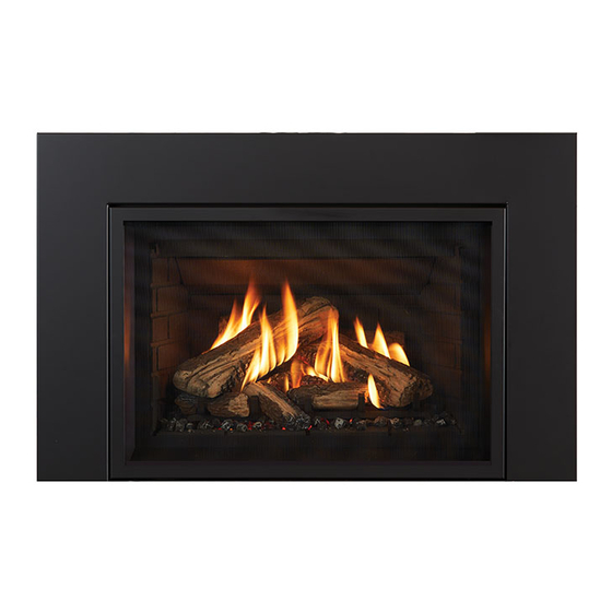
- Page 2 The Regency gas insert series of handcrafted appliances is designed to provide you with all the warmth and charm of a fireplace at the flick of a switch. The Gi29LE is approved by Intertek for safety and efficiency. As it also bears Regency’s mark, it promises economy, comfort, and security for many trouble-free years to come.
-
Page 3: Table Of Contents
table of contents Dimensions Faceplate Surround Installation ............ 53 Hearth Trim Installation - Trimming to Height ........ 54 Hearth Trim Installation - Mounting Hearth Trim ......55 Unit Dimensions ................4 Faceplate Dimensions ..............5 Optional Wall Thermostat ............56 Supplied Remote Control ............ -
Page 4: Unit Dimensions
dimensions Unit Dimensions Letter Description Dimensions Dimensions Letter Description Dimensions Dimensions (inches) (mm) (inches) (mm) Width 29-3/4" 756 mm Gas Inlet Front Depth 12-7/16" 316 mm Outerbox Width 28-5/16" 719 mm Electrical Access Height 1-1/8" 29 mm Outerbox Height 20-1/4" 514 mm Electrical Access Rear Depth 7-1/2"... -
Page 5: Faceplate Dimensions
dimensions Faceplate Dimensions Three-Sided Faceplate Four-Sided Faceplate Dimensions Faceplate Width Height Depth Bottom Height Regular Faceplate 40-3/16" (1021 mm) 26" (660 mm) 1-1/4" (32 mm) Regular Faceplate w/ Premium 40-13/16" (1021 mm) 26-3/8" (670 mm) 1-11/16" (43 mm) Surround Flush Faceplate 40-3/16"... -
Page 6: Owner's Information
Copy of Safety Label A copy of the label that accompanies each Gi29LE gas insert is below. Regency units are constantly improving. Check the safety Duplicate Serial number/Copie No de série Gi29LE Serial Label label on the unit and if it is different from the copy provided DO NOT REMOVE THIS LABEL / Listed: VENTED GAS FIREPLACE HEATER/FOYER AU GAZ À... -
Page 7: Know Your Appliance
dimensions Gas Installation Checklist REGENCY GAS INSTALLATION CHECKLIST This general checklist does not contain all pertinent installation details or specifics and does not supersede the guidelines in this manual. Your Regency dealer/installer should use it in conjunction with manual instructions. Please follow all local codes and jurisdictions in authority. Customer: Date Installed: Install Address:... - Page 8 installation REGENCY GAS INSTALLATION CHECKLIST Finishing If applicable, is only noncombustible material installed in the noncombustible areas? Do clearances meet installation and manual requirements? Do the mantels and/or projections comply with the installation manual? If applicable, was the solid fuel fireplace warning plate installed? Appliance Media Setup Do commands from the remote or wall switch light the pilot and main burner? Are the burner media/log set, glass door, and screen installed per instructions in the manual?
- Page 9 owner's information Know Your Appliance LETTER DESCRIPTION MORE INFO ON PAGE SCREEN ON/OFF SWITCH GLASS DOOR REMOTE SYNC SWITCH IFC BOARD 13-15 BATTERY BACKUP HOLDER VALVE STEPPER MOTOR GAS SHUT-OFF VALVE AIR SHUTTER ADJUSTMENT ARM Gi29 Direct Vent Gas Insert |...
-
Page 10: Important Message
At pressures over 1/2 psig, the pipe to the unit YOUR WARRANTY AND MAY CAUSE must be disconnected. The Gi29LE gas insert must be installed in A SERIOUS HOUSE FIRE. accordance with the instructions in this manual; read them carefully before installing the unit. Consult Gas Max. -
Page 11: Lighting Procedure
owner's information Lighting Procedure IMPORTANT: The remote control system supplied with this appliance must Note: The first try for ignition will last approximately 60 seconds. If there is no be used for lighting with the ON/OFF key on the hand held transmitter. Prior to operating this appliance, please read the remote control operat- flame ignition (rectification) the board will stop sparking for approximately ing instructions (packaged with remote control) to understand how to... - Page 12 owner's information Temperature indication Display Remote-Flame Control With the system in the "OFF" position, press the Thermostat Key and the The Proflame has six (6) flame levels. With the system on, and the Mode Key at the same time. Look at the LCD screen on the transmitter flame level at the maximum in the appliance, pressing the Down Arrow to verify that a C or F is visible to the right of the room temperature Key once will reduce the flame height by one step until the flame is...
- Page 13 owner's information Smart Thermostat (Transmitter Operation) Remote dimmer control (Light) The auxiliary function controls the AUX power outlet by the dimmable light control. To activate this function use the Mode Key (fig. 1) to index The Smart Thermostat function adjusts the flame height in accordance to the AUX icon (fig.
- Page 14 owner's information Continuous Pilot/Intermittent Pilot (CPI/IPI) Key Lock selection This function will lock the keys to avoid unsupervised operation. To activate this function, press the MODE and UP Keys at the same Note: Power vent models do not have a Continuous time (fig.
-
Page 15: Proflame Ii Remote Control Operating Instructions
owner's information Proflame II Remote Control Operating Instructions IMPORTANT:The Proflame Transmitter 2 is an integrated part of the TECHNICAL DATA Proflame 2 System, which consists of these elements: REMOTE CONTROL • Proflame 2 Transmitter, to be used in conjunction with: •... -
Page 16: Copy Fo Lighting Plate Instructions
owner's information Copy of Lighting Plate Instructions FOR YOUR SAFETY READ BEFORE LIGHTING POUR VOTRE SÉCURITÉ – À LIRE AVANT LA MISE EN MARCHE WARNING: If you do not follow these instructions exactly, a fire or explosion may result causing property damage, personal injury or loss of life. -
Page 17: Installer's Information
Must be removed: 3. The appliance should be inspected before use 1 -Damper The Gi29LE gas insert was tested and approved and at least annually by a professional service 2- Grate (with log set) for venting into any masonry or approved solid person. -
Page 18: Installation Checklist
installer's information Installation Checklist Minimum Fireplace Dimensions Before installing the vent system, ensure that the The minimum fireplace clearances & dimensions for the Regency gas insert are shown in the following damper plate is open and secure to prevent it from diagram: falling and crushing the liner. -
Page 19: Minimum Fireplace Opening Sizes With Varying Faceplate/Backing Plate Options
installation Minimum Fireplace Opening Sizes with Varying Faceplate/Backing Plate Options Dimensions Minimum Install Minimum Install Minimum Install Minimum Rear Taper Depth Faceplate Width Height Depth Width Regular Faceplate 28-7/16" (722 mm) 20-1/4" (514 mm) 16-11/16" (424 20" (508 mm) 2-13-16" (71 mm) Regular Faceplate w/ Backing Plate 30-7/8"... -
Page 20: Minimum Clearances To Combustibles
installation Minimum Clearances to Combustibles The clearances listed below are minimum distances unless otherwise stated. A major cause of fires is failure to maintain required clearances (airspace) to combustible materials. It is of the greatest importance that this decorative gas appliance is installed only in accordance with these instructions. -
Page 21: 2-1/2" Mantel Deflector
installation Mantel Clearances Without Mantel Deflector Mantel Clearances with 2-1/2" Mantel Deflector 30" 30" 28" 28" 26" 26" 24" 24" 22" 22" 20" 20" 18" 18" 16" 16" 14" 14" 12" 12" 10" 10" 8" 8" 6" Deflector 6" 4" 4"... -
Page 22: Using Steel Studs And Concrete Board Over Masonry Brick Fireplace
installation Using Steel Studs and Concrete Board Over Masonry Brick Fireplace The masonry front brick facing can be removed and replaced with non-combustible materials such as steel studs and concrete board/dura rock/micor board as per diagram 1, only if safe to do so. Steel stud may also be placed in front of the masonry brick if left in place. This is the preferred method depending on the condition of the masonry brick fireplace. -
Page 23: Levelling Legs Adjustment
installation Leveling Legs Adjustment • The leveling of the appliance must be done prior to hooking up gas line and vent system. 1. The leveling bolts can be installed with bolts from above or below 4. The front leveling bolts can be accessed from the front of the insert, on (preferred method) to level the appliance. -
Page 24: Gas Connection
installation Gas Connection Only people licensed to work with gas piping may make the gas connections to this appliance. 1. If the appliance is installed into an existing chimney system, thoroughly clean the masonry or factory-built fireplace. 2. The appliance has an opening on the left side of the control compartment. A 3/8”... -
Page 25: Alternate Approved Vertical Termination Caps/Adaptor
installation Alternate Approved Vertical Termination Caps/Adaptor Alternate Approved Caps 46DVA-VC Vertical Termination Cap 46DVA-VCH High Wind Cap 46DVA-GK 3" Co-linear Adaptor with flashing In areas with consistently high winds, we recommend using the Simpson Dura-Vent System (46DVA-GK adaptor and 46DVA-VCH high-wind cap). The air intake pipe must be attached to the inlet air collar of the termination cap. -
Page 26: Restrictor Adjustment
installation Restrictor Adjustment Tools needed • Phillips screwdriver Gently lift the screen assembly up and out. Refer to the Screen Removal section. Remove the glass door. Refer to the Glass Door Removal section. Refer to the vent chart to determine the restrictor setting. Locate the restrictor plates and screws. -
Page 27: Vertical Venting/Restrictor Settings For Ng And Lp
installation Vertical Venting/Restrictor Settings for NG and LP Setting #3 Setting #4 4-1/2" open 2" open Setting #2 2-1/2" open Setting #1 Setting #2 1" open 2-1/2" open Gi29 Direct Vent Gas Insert |... -
Page 28: Horizontal Co-Linear Vent Kit (Masonry Fireplaces Only)
installation Horizontal Co-Linear Vent Kit (Masonry Fireplaces Only) APPLICATION This instruction applies to the DuraVent Direct Vent Pro termination system and is intended as a supplement to the applicable Direct Vent Pro instruc- tions. This termination and venting system and the gas appliance were tested and listed by an accredited test agency. Kit # 46DVA-HCL33 includes: 1 Horizontal Termination Cap Two 10' (3 m) long x 3"... -
Page 29: Flue Collar Installation/Removal
installation Flue Collar Installation/Removal 1. Detach the flue collar from the unit by removing the screws and sliding 4. The tabs on the insert will seal the flue collar against the intake inlet the plate backward. and exhaust outlet. Secure with the two screws removed in step 1. Connector plate screws 2. -
Page 30: Air Shutter Adjustment
- Pull out to close air shutter + Pull in to open the air shutter Unit Fuel Type Min. Air Shutter Setting* Gi29LE 3/16" (5 mm) Gi29LE 1/4" (6 mm) *At higher elevations, air shutter settings may have to be opened more to compensate. -
Page 31: Ng System Data
installation Pilot Adjustment 885 S.I.T. Valve Description NG System Data Min. Supply Pressure 5" WC (1.25kPa) Periodically check the pilot flames. Correct 1. 6 Stage flame adjustment flame pattern has two strong blue flames: 2. Pilot adjustment Low Setting Man. 1.1 WC (0.27 kPa) 1 flowing around the flame sensor and 1 Pressure... -
Page 32: Gas Shut Off Procedure
installation Gas Shut Off Procedure Slide the shut-off arm out. Slide shut-off arm back in. Turn gas valve to desired position. If needed, use a flathead screw- driver to turn valve. CLOSED OPEN Alternatively, rotate the knob to turn it into a handle for more lever- age. -
Page 33: Conversion From Natural Gas To Propane
Conversion Kit # 311-969 from NG to LPG Conversion from Natural Gas to Propane for Gi29LE using SIT 885 NOVA Gas Valve THIS CONVERSION MUST BE DONE BY A QUALIFIED GAS FITTER IF IN DOUBT DO NOT DO THIS CONVERSION !! 11. Slide out IFC. - Page 34 Gi29LE LP Conversion installation 14. Reverse steps 7 to 2. 15. Attach the "This unit has been converted to LPG" label near or on top of the serial decal. 16. Replace the yellow "Natural Gas" label with the red "LPG" label. 17. Adjust the aeration settings - see the "Air Shutter Adjustment" section in themanual. 18. Start the appliance (see the "Lighting In- structions" section in the manual). Ensure that pilot and burner ignition are completed without delay. Check your inlet and outlet pressures at full load. With a soapy solution, leak test the entire system. Verify correct flame and pilot appearance. Wires must be secured by gray clips when reinstalling. | Gi29 Direct Vent Gas Insert 920-520 07/22/22...
-
Page 35: Derating Kit
Gi29L installation Derate Kit # 311-980 for NG Only Derating Kit for Gi29L using SIT 820 NOVA Gas Valve THIS CONVERSION MUST BE DONE BY A QUALIFIED GAS FITTER IF IN DOUBT DO NOT DO THIS CONVERSION !! 6. Remove the burner tray (2 screws). Reverse steps 7 to 2. -
Page 36: Panel Installation
installation Gi29 Panel Installation (Part # 311-901, 311-903, 311-904, 311-905, 311-906, 311-907) Panel Installation • Brick/steel/glass panels may discolor a little during operation. This is normal and should not be considered a defect. • Black glass panels: All hand and fingerprints MUST be cleaned off with a soft cloth. Use an ammonia-based cleaner (i.e. glass cleaner) to remove prints before applying heat to the unit. - Page 37 Gi29 Panel Installation installation (Part # 311-901, 311-903, 311-904, 311-905, 311-906, 311-907) For brick/steel panels: 4. Insert the left panel and push until it touches the rear panel. 5. Insert the right panel and push until it touches the rear panel. For glass panels: 6.
- Page 38 Gi29 Panel Installation installation (Part # 311-901, 311-903, 311-904, 311-905, 311-906, 311-907) 9. Install the front panel(s)* by placing between the front of the firebox and the media tray. If the front panel is too tight, there are adjustment slots on the media tray to allow for looser fitting.
-
Page 39: Log Set Installation
installation Gi29 Oak Log Set Installation (Part # 311-934) Log Set Installation Read the instructions below carefully and refer to the images. If the logs are broken, do not use the unit until they are replaced. Improper positioning of the logs and may create carbon build-up and can alter the unit's performance. - Page 40 The glass can cover parts of the front brick panel. There will be extra glass if you are installing a Gi29L or Gi29LU. Gi29LE. The screws may need loosening before you can slide the grate into place.
- Page 41 installation Gi29 Oak Log Set Installation (Part # 311-934) 6. Carefully lay Log 1 on the two pins behind the burner. Make sure the left part of the log does not hit the left portion of the burner. Log 1 7.
- Page 42 installation Gi29 Oak Log Set Installation (Part # 311-934) 8. Place Log 3 on the pin and rotate it until it touches the tab shown below. Ensure that Log 3 is resting directly on the tray with no embers underneath. Log 3 9.
- Page 43 installation Gi29 Oak Log Set Installation (Part # 311-934) 10. Place Log 5 on the pin under the right burner. Log 5 11. Place Log 6 on the grate with the notch on the middle of the log sitting on the first grate bar and the flat section pointing up. Log 6 does not sit on the front panel - it rests on the tab next to the second grate bar.
- Page 44 installation Gi29 Oak Log Set Installation (Part # 311-934) 12. Place Log 7 with the notch (shown below) resting on the upper right corner of the second grate bar. Rest the bottom right end of the log on the front panel, ensuring it does not protrude over the bottom edge of the firebox and that there are no embers underneath. This ensures Log 7 sits properly on the grate and does not interfere with the operation of the glass door.
- Page 45 installation Gi29 Oak Log Set Installation (Part # 311-934) 14. Place Log 9 on the right end of the burner. The log rests on the burner, not on the fifth grate bar. Log 9 15. Place Log 10 on the left side of the burner. Log 10 should not touch Log 6. Readjust the positioning of Log 6 if necessary, enuring it is rest- ing on the tab beside the second grate bar.
- Page 46 installation Gi29 Oak Log Set Installation (Part # 311-934) Log 1 Log 2 Log 3 Log 10 Log 9 Log 4 Log 5 Log 8 Log 6 Log 7 Final Placement | Gi29 Direct Vent Gas Insert 920-434 01.18.22...
-
Page 47: Screen Removal
installation Screen Removal 1. Gently lift screen assembly out. 2. Place screen assembly where it will not be scratched or broken. Gi29 Direct Vent Gas Insert |... -
Page 48: Glass Door Removal
installation Glass Door Removal 1. Locate and remove the four forward-facing Phillips head screws in the locations shown. 2. Lift glass door up and out. 3. Place glass door in a safe place where it will not be scratched or broken. | Gi29 Direct Vent Gas Insert... -
Page 49: Faceplate/Finishing Trim Installation
installation Gi29 Faceplate/Finishing Trim Installation (Part # 311-910, 311-912, 311-913, 311-914, 311-915) Faceplate/Finishing Trim Installation 3. Fasten the four screws on both sides to attach the faceplate/finish- These instructions are for use with the following products: ing trim. Part # Description 311-910 Faceplate Regular 3-Sided Black... -
Page 50: Backing Plate Installation
installation Gi29 Backing Plate Installation (Part # 311-936, 311-937, 311-938) Backing Plate Installation ?. Remove the four screws located at the front of the unit. These instructions are for use with the following products: 4. Remove the four screws at the front of the unit. Part # Description 311-936... - Page 51 Gi29 Backing Plate Installation installation (Part # 311-936, 311-937, 311-938) 8. Pull the backing plate as far forward as possible against the face- plate, then retighten the screws on both sides. 9. Install the compact screen. Gi29 Direct Vent Gas Insert |...
-
Page 52: Mantel Deflector Installation
installation Gi29 Mantel Deflector Installation (Part #311-940) Mantel Deflector Installation 1. Fasten the two screws provided from the back to attach the mantel 3. Install the compact screen. deflector. 2. Mantel deflector installed. | Gi29 Direct Vent Gas Insert... -
Page 53: Faceplate Surround Installation
installation Gi29 Faceplate Surround Installation (Part # 311-920, 311-921, 311-922, 311-923, 311-924) Faceplate Surround Installation 3. Lift the faceplate and faceplate surround up from the top edge and These instructions are for use with the following products: refer to "Faceplate / Finishing Trim Installation". PART # Description 311-920... -
Page 54: Hearth Trim Installation - Trimming To Height
installation Gi29 Hearth Trim Installation (Part # 311-941 ) TRIMMING TO HEIGHT Hearth Trim Installation - Trimming to Height 1. Remove the lower section of hearth trim by pulling evenly from both 3. Slide the lower section back into the clips on the rear of the upper sides. section. 2. If using a grinder (recommended): trim the lower section to height referring to the installation table for the amount to remove. Installation Table Required install height Height to cut off lower section 6” (Max) None 5 1/2” 1/2” 5” 1”... -
Page 55: Hearth Trim Installation - Mounting Hearth Trim
Gi29 Hearth Trim Installation (Part # 311-941 ) installation MOUNTING HEARTH TRIM Hearth Trim Installation - Mounting Hearth Trim 1. Loosely attach the hearth trim using the slots in the unit's base and 2b. With premium surround: slide the hearth trim as far back as pos- the included screw. sible (careful not to scratch it) and tighten the screws. 2a. Without premium surround: slide the hearth trim as far forward as possible (careful not to scratch it) and tighten the screws. 920-483 12.17.21 Gi29 Direct Vent Gas Insert |... -
Page 56: Optional Wall Thermostat
installation Optional Wall Thermostat Supplied Remote Control A wall thermostat may be installed if desired; follow Use the FPI remote control kit supplied with this the wiring diagram below. FPI offers an optional unit. Use of other systems may void your war- programmable thermostat, but any 250-750 millivolt ranty. -
Page 57: Wiring Diagram
911-071/P Fan EBM 60mm x 300mm 911-188 Valve-NG 115 Volts 911-189 Valve-LP 911-377 Wire 4 pos IFC Fan/Light 911-242 Reset Switch Gi29LE 311-526 Main Switch Assembly 911-312 Light Assembly Bottom 911-297 Halogen Bulb (Each) Gi29 Direct Vent Gas Insert |... -
Page 58: Operation
operating instructions Operating Instructions Shutdown Procedure On/Off Switch 1. Press the ON/OFF button on the remote Before operating this appliance, proceed through the following checklist. 2. If service is to be performed - you must discon- nect power and shut off gas to the unit. 1. -
Page 59: Normal Operating Sounds Of Gas Appliances
maintenance Normal Operating Sounds of 4. Check the burner’s position and condition pe- 6. Keep the area near the appliance clear and free riodically, as well as the burner flame, making from combustible materials, gasoline, and other Gas Appliances sure it is steady, not lifting or floating. If there flammable vapours and liquids. -
Page 60: Door Glass
maintenance Door Glass General Vent Maintenance Your Regency insert is supplied with high Conduct an inspection of the venting system -temperature Neoceram glass that will withstand semiannually. Areas to inspect are as follows: the highest heat your unit can produce. If your glass requires cleaning, we recommend using an 1. -
Page 61: Fan Replacement
maintenance Fan Replacement • To access the side and rear panels, disconnect the gas and venting (see the venting and flue installation sections in this manual for steps). You cannot access the blower from the front of the appliance. 1. Shut the power off. 2. -
Page 62: Valve Replacement
maintenance Valve Replacement Before you begin: • Shut off the gas supply to the unit. • Disconnect all electrical supply to the unit. • Remove door, see glass door removal section for instructions. Always let the appliance cool to room temperature before servicing. •... - Page 63 maintenance 7. Disconnect the incoming gas ex line from the ball valve. Slide the pilot wires through the grommet to remove. 5. Disconnect the green, orange and yellow cables from the valve. 7. Disconnect the incoming gas flex line from the ball valve. Slide the pilot 5.
-
Page 64: Gas Maintenance - Recommended Annual Routine
Gas Maintenance maintenance Gas Maintenance - Recommended Annual Routine Recommended Annual Routine Maintenance for Gas Fireplaces, Stoves and Inserts In order for your Regency appliance to continue to provide comfort to your home periodic maintenance must be performed to ensure it is operating at peak efficiency. The items in the list should be checked by a licensed gas service technician during the annual service check. Your unit may require more frequent maintenance checks if you notice any changes in how it operates. Operational changes to look for can include, but are not limited to, extended start up time, increased fan noise, residue/carbon build up, white build up on the glass/firebox, increased operating noise etc. Should any of these or other conditions arise, discontinue use and schedule a service check with your local licensed gas technician. The list below shows items your licensed service technician will need to check and service at least annually. Clean Inspect Check • Glass • Pilot assembly • Voltage on thermocouple/thermopile (mil- • Interior bricks / panels • Burner livolt models) • Burner ports & burner air shutter •... -
Page 65: Parts - Main Assembly
parts list Parts - Main Assembly 11 15 Gi29 Direct Vent Gas Insert |... - Page 66 Inner Panel Retainer Clip Left 904-918 Front Levelling Bolt 1/4-20 x 3/4 Hex Hd Blk Oxide 311-108 Bracket Flue 911-377 Wire 4 Pos IFC Fan and Light Gi29LE 311-120F Right Plate Gas/Electrical Access 911-173 Wire Harness IFC No CPI Switch 584.924 311-084...
-
Page 67: Faceplates/Accessories
parts list Faceplates/Accessories ITEM PART # DESCRIPTION ITEM PART # DESCRIPTION 312-936 Backing Plate Oversized 311-940 Mantel Deflector 311-937 Backing Plate Custom 3-Sided* 311-941 Adjustable Hearth Trim 311-938 Backing Plate Custom 4-Sided* 311-934 Oak Log Set 312-193 Bracket Backing Plate 311-901 Brick Panel Standard Brown 311-920... -
Page 68: Warranty
warranty Limited Lifetime Warranty FPI Fireplace Products International Ltd. (for Canadian customers) and Fireplace Products U.S., Inc. (for U.S. customers) (collectively referred to herein as “FPI”) extends this Limited Lifetime Warranty to the original purchaser of this appliance provided the product remains in the original place of installation. The items covered by this limited warranty and the period of such coverage is set forth in the table below. - Page 69 warranty At all times FPI reserves the right to inspect reported complaints on location in the field claimed to be defective prior to processing or authorizing of any claim. Failure to allow this upon request will void the warranty. All warranty claims must be submitted by the dealer servicing the claim, including a copy of the Bill of Sale (proof of purchase by you).
- Page 70 warranty Limitations of Liability: The original purchaser’s exclusive remedy under this warranty, and FPI’s sole obligation under this warranty, express or implied, in contract or in tort, shall be limited to replacement, repair, or refund, as outlined above. IN NO EVENT WILL FPI BE LIABLE UNDER THIS WARRANTY FOR ANY INCIDENTAL OR CONSEQUENTIAL COMMERCIAL DAMAGES OR DAMAGES TO PROPERTY.
- Page 71 warranty Product Registration and Customer Support: Thank you for choosing a Regency Fireplace. Regency strives to be a world leader in the design, manufacture, and marketing of hearth products. To provide the best support for your product, we request that you complete a product registration form found on our Web Site under Customer Care within ninety (90) days of purchase.
- Page 72 warranty | Gi29 Direct Vent Gas Insert...
- Page 73 notes Gi29 Direct Vent Gas Insert |...
- Page 74 notes | Gi29 Direct Vent Gas Insert...
- Page 76 Installer: Please complete the following information Dealer Name & Address: __________________________________________________________________ ______________________________________________________________________________________ Installer: ______________________________________________________________________________ Phone #: ______________________________________________________________________________ Date Installed: __________________________________________________________________________ Serial #:_______________________________________________________________________________ Printed in Canada Regency and Regency Horizon are trademarks of FPI Fireplace Products International Ltd. ® © Copyright 2022, FPI Fireplace Products International Ltd. All rights reserved.