Table of Contents
Advertisement
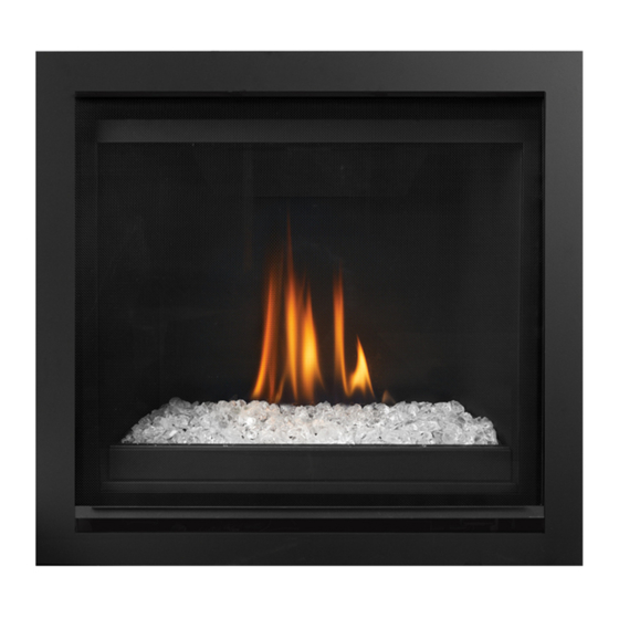
Grandview
Warning
Fire or Explosion Hazard
Failure to follow safety warnings exactly could result in serious
injury, death, or property damage.
Do not store or use gasoline or other flammable vapors and liquids in the vicinity of this or any other appliance.
WHAT TO DO IF YOU SMELL GAS
• Do not try to light any appliance.
• Do not touch any electrical switch: do not use any phone in your building.
Leave the building immediately.
• Immediately call your gas supplier from a neighbour's phone. Follow the gas supplier's instructions.
• If you cannot reach your gas supplier, call the fire department.
Installation and service must be performed by a qualified installer, service agency or the gas supplier.
Tested by:
Certified to/Certifié pour: ANSI Z21.88-2017
FPI FIREPLACE PRODUCTS INTERNATIONAL LTD. 6988 Venture St., Delta, BC Canada, V4G 1H4
920-271a
®
Gas Fireplace
CSA 2.33-2017
CSA 2.17-2017
G600EC
Installer: Please complete the details on the back cover and leave
this manual with the homeowner.
Homeowner: Please keep these instructions for future reference.
Owners &
Installation Manual
MODEL: G600EC
Medium DV Gas Fireplace
www.regency-fire.com
10.22.20
Advertisement
Table of Contents

Related Manuals for Regency Fireplace Products Grandview G600EC-NG


Summary of Contents for Regency Fireplace Products Grandview G600EC-NG
- Page 1 Owners & Grandview G600EC ® Installation Manual Gas Fireplace MODEL: G600EC Medium DV Gas Fireplace www.regency-fire.com Warning Fire or Explosion Hazard Failure to follow safety warnings exactly could result in serious injury, death, or property damage. Do not store or use gasoline or other flammable vapors and liquids in the vicinity of this or any other appliance. WHAT TO DO IF YOU SMELL GAS •...
- Page 2 To the New Owner: Congratulations! You are the owner of a state-of-the-art Gas Fireplace by REGENCY . The Grandview™ G600EC has been designed to provide ® you with all the warmth and charm of a wood fireplace at the flick of a switch. The Grandview™ G600EC has been approved by Intertek for both safety and efficiency.
- Page 3 MANUFACTURED MOBILE HOME REQUIREMENTS INFORMATION FOR MOBILE/MANUFACTURED HOMES AFTER FIRST SALE This Regency product has been tested and listed by Intertek as a Direct Vent Wall Furnace to the following ® standards: to Vented Gas Fireplace Heaters ANSI Z21.88-2017 • CSA 2.33-2017 and Gas-fired Appliances for Use at High Altitudes CSA 2.17-2017.
- Page 4 WARNING CARBON MONOXIDE POISONING HAZARD Failure to follow the steps outlined below for each appliance connected to the venting system being placed into operation could result in carbon monoxide poisoning or death. The following steps shall be followed for each appliance connected to the venting system being placed into operation, while all other appliances connected to the venting system are not in operation: 1.
-
Page 5: Table Of Contents
table of contents Rigid Pipe Venting Systems—Horizontal or Vertical Copy of Safety Decal ...............7 Terminations ................52 Decal Location .................7 Venting Arrangements—Horizontal Termination-Rigid Pipe Unit Dimensions ..............9 and FPI Direct Vent System (Flex) ........53 Venting Arrangements Vertical Termination—Rigid Pipe Owner's Information System and Vertical Flex Kit to Same Limitations ....54 Before You Start ..............10 Horizontal Terminations Two (2) 90°Elbows ......55... - Page 6 table of contents Light Bulb Replacement—Bottom Lights + Top Light ....85 Valve Replacement ..............86 IFC Replacement ..............87 Gas Appliance Maintenance ..........88 Parts Main Assembly Diagram ............89 Main Assembly—Parts List ............90 Optional Accessories .............91 Warranty ................92 Grandview® G600EC Gas Fireplace...
-
Page 7: Copy Of Safety Decal
safety decal This is a copy of the label that accompanies each Grandview™ G600EC Direct Vent Gas Fireplace. We have printed a copy of the contents here for your review. NOTE: Regency units are constantly being improved. Check the label on the unit and if there is a difference, the label on the unit is the correct one. ®... - Page 8 installer's information MA Code - CO Detector (for the State of Massachusetts only) 5.08: Modifications to NFPA-54, Chapter 10 (2) Revise 10.8.3 by adding the following additional requirements: (a) For all side wall horizontally vented gas fueled equipment installed in every dwelling, building or structure used in whole or in part for residential purposes, including those owned or operated by the Commonwealth and where the side wall exhaust vent termination is less than seven (7) feet above finished grade in the area of the venting, including but not limited to decks and porches, the following requirements shall be satisfied:...
-
Page 9: Unit Dimensions
dimensions Unit Dimensions 4" 101mm " 172mm 16" 406mm " 439mm " 16" 811mm 405mm OUTSIDE FINISH " " 246mm 729mm CLEAN FRONT 26-1/8" (664 mm) GAS INLET ELECTRICAL INLET " " " 41mm 191mm 213mm " 268mm 37 1 37 3 33-1/2"... -
Page 10: Owner's Information
owner's information Before You Start YOUNG CHILDREN SHOULD BE CARE- FULLY SUPERVISED WHEN THEY ARE Safe installation and operation of this appliance IN THE SAME AREA AS THE APPLI- involves common sense. This is echoed in the ANCE. TODDLERS, YOUNG CHILDREN reminders the Canadian Safety Standards and AND OTHERS MAY BE SUSCEPTIBLE ANSI Standards require us to provide you, which... -
Page 11: Lighting Procedure
owner's information Lighting Procedure IMPORTANT: The battery holder and ON/OFF key on the hand held transmit- The system will need to be reset as follows: ter of the remote control system supplied with this appliance provides several options for startup/operation. a) Turn the system off by pressing the ON/OFF button on the remote. -
Page 12: Copy Of Lighting Plate Instructions
owner's information Copy of Lighting Plate Instructions FOR YOUR SAFETY READ BEFORE LIGHTING POUR VOTRE SÉCURITÉ – À LIRE AVANT LA MISE EN MARCHE This appliance must be installed in accordance with local codes, if any; if none, follow the National Fuel Gas Code, ANSI Z223.1/NFPA 54, or Natural Gas and Propane Installation Codes, CSA B149.1. -
Page 13: Proflame Ii Remote Control Operating Instructions
owner's information Proflame II Remote Control Operating instructions IMPORTANT:The Proflame Transmitter 2 is an integrated part of the TECHNICAL DATA Proflame 2 System, which consists of these elements: REMOTE CONTROL • Proflame 2 Transmitter, to be used in conjunction with: •... - Page 14 owner's information Temperature indication Display Remote-Flame Control With the system in the "OFF" position, press the Thermostat Key and The Proflame has six (6) flame levels. With the system on, and the flame the Mode Key at the same time. Look at the LCD screen on the transmit- level at the maximum in the appliance, pressing the Down Arrow Key ter to verify that a C or F is visible to the right of the room temperature once will reduce the flame height by one step until the flame is turned off.
- Page 15 owner's information Smart Thermostat (Transmitter Operation) Remote Dimmer Control (Bottom Ember Lights) The bottom ember lights are located near the dimmable light control. To The Smart Thermostat function adjusts the flame height in accordance activate this function use the Mode Key (fig. 1) to index to light bulb (fig. to the difference between the set point temperature and the actual room 15 &...
- Page 16 owner's information Continuous Pilot/Intermittent Pilot (CPI/IPI) 4. The screen will show either "Clr" or "Set" as the first option available is to disable or enable a mode. selection 5. "Clr" will remove a mode—use the up or down arrow while holding Note: Power vent models do not have a Con- down ON/OFF and MODE (mode icon will disappear once removed).
-
Page 17: Safety Screen And Glass Door Removal
owner's information Safety Screen Removal Glass Door Removal 1. To remove the glass door - place both hands on either 1. Slide screen side of the latch. Pull forward then up to unlock, repeat on opposite side. Important: After releasing the latches, support the weight of the door. -
Page 18: Installer's Information
installer's information Important Message 9. Wear gloves and safety glasses for protection while doing required maintenance. SAVE THESE INSTRUCTIONS 10. Be aware of electrical wiring locations in walls and ceilings when cutting holes for termination. The G600EC Direct Vent Fireplace must be installed in accordance with these instructions. -
Page 19: Installation Checklist
installer's information Installation Checklist This includes: 4. This appliance is Listed for bedroom installations using the standard Remote (millivolt thermostat 1. Clocking the appliance to ensure the correct system). Some areas may have further require- 1. Locate appliance firing rate (rate noted on label 21,000 Btu/h ments, check local codes before installation. -
Page 20: Clearance/Framing And Venting Configurations
installer's information Clearance/Framing and Venting Configurations The G600EC is designed to allow for unique installation options—depending on the desired finish. Please review the options and follow the specific clearance, framing, and finishing options for that application. The applications are as follows: Cool Wall installation-Clean Front &... -
Page 21: Cool Wall Installation (Combusitble Finishing)
installation Cool Wall Installation (Combustible Finishing) Cool Wall Install: • Vented chase • Combustible material can be used all around the fireplace • Combustible framing Clean Front Outside Finish w/ Finishing Trim Clean Front Non Combustible Installation Install: • Non-vented chase •... -
Page 22: Unit Assembly Prior To Installation
installation Unit Assembly Prior to Installation (Nailing Flange Installation) After the framing has been built, the nailing Flanges will need to be set depending on the Left Nailing Flange depth of finishing material being used. Up to 11/4” total material thickness can be used, Right Nailing Flange including the backing material. -
Page 23: Nailing Flange Installation
installation Nailing Flange Installation Finishing Material Depth Flush 1/4 " Setting 3/4" 11/4" Front of Fireplace � - - - - - -.:-- ··-..� , 1 '- �> \I t' ._ . .,.,,, , . • • · - - -- - -- - - •... - Page 24 installation 6. Slot the Header Deflector onto the back screws, then secure the with a screw through the remaining front hole on each flange. Header Deflector CLEAN FRONT OUTSIDE FINISH *Distance to combustible material varies with install* Backing Material (Drywall etc.) 1-1/4"...
-
Page 25: Cool Wall Clearances
installation Cool Wall Clearances The clearances listed below are minimum distances unless otherwise stated: A major cause of chimney related fires is failure to maintain required clearances (air space) to combustible materials. It is of the greatest importance that this fireplace and vent system be installed only in accordance with these instructions. Caution Requirements WARNING Fire hazard is an extreme risk... -
Page 26: Cool Wall Mantel Clearances
installation Cool Wall Mantel Clearances Due to the extreme heat this fireplace emits, the mantel clearances are critical. Combustible mantel clearances from top of front facing are shown in the diagram below. Mantel Clearances 12" (305 mm) Combustible 7" (178 mm) 1"... -
Page 27: Cool Wall Installation-Framing
installation Cool Wall Installation—Framing Framing Dimensions Description Cool Wall Framing Width 33-1/2" (851 mm) Framing Height 40" (1016 mm) Framing Depth 15" (381 mm) Corner Facing Wall Width 37-1/4" (946 mm) Corner Facing Wall Width 52-1/2" (1334 mm) Framed Chase Ceiling Enclosure 74-1/2"... -
Page 28: Cool Wall Installation-Cool Wall Clearances
installation Cool Wall Installation-Cool Wall Conversion 6. Remove the inner cover piece and secure it to the left rear side of 1. Remove safety screen from unit as per manual. the unit with one screw as shown. 2. Remove the three screws from the top of the unit, holding the top cover in place. -
Page 29: Chase Venting
installation Chase Venting Note: The enclosure opening cannot be any lower than 0-2" (0-51mm) from the top of the enclosure for all installations. Minimum height of enclosure from base of appliance is 74-1/2" (1892mm). CHASE VENTING A minimum 58 in opening in the enclosure is required to maintain safe opeating temperatures. -
Page 30: Chase Vent Installation-Cool Wall
installation G600EC G600 Chase Vent Installation—Cool Wall CHASE VENT INSTALLATION—COOL WALL G600EC/G600C (Part #776-941) (PART #776-941) Framed opening must be at least 2 3/8” (60 mm) tall, and at least 29 3/8” (746 mm) wide to accomodate the chase vent. The top of the chase vent opening must be 2”... -
Page 31: Clean Front Installation (Non Cool Wall)-Clearances
installation Clean Front Installation (Non Cool Wall)—Clearances The clearances listed below are minimum distances unless otherwise stated: A major cause of chimney related fires is failure to maintain required clearances (air space) to combustible materials. It is of the greatest importance that this fireplace and vent system be installed only in accordance with these instructions. -
Page 32: Clean Front Installation (Non Cool Wall)-Mantel Clearances
installation Clean Front Installation (Non Cool Wall)—Mantel Clearances Due to the extreme heat this fireplace emits, the mantel clearances are critical. Combustible mantel clearances from top of front facing are shown in the Diagram on the right. Note: Ensure the paint that is used on the mantel and the facing is "High Quality" or the paint may discolour. Mantel Clearances 17"... -
Page 33: Clean Front Installation (Non Cool Wall)-Mantel Leg Clearances
installation Clean Front Installation (Non Cool Wall)—Mantel Leg Clearances Allowable mantel leg projection TopView (38mm) Side opening 2" of fireplace 4-1/4" (51mm) (108mm) 1-1/2" *28-3/4" (729 mm) 32-1/2" (826mm) (38mm) 5" Overall Fireplace Width (Clean Finish) Overall Fireplace width 3" (76mm) 6-7/8"... -
Page 34: Clean Front Installation-Framing (Non Cool Wall)
installation Clean Front Installation—Framing (Non Cool Wall) Framing Dimensions Description G600EC - Non Cool Wall Framing Width 33-1/2" (851 mm) Framing Height 40" (1016 mm) Framing Depth 16-3/4" (452 mm) P (Top Vent Only) Corner Facing Wall Width 40" (1016 mm) Q (Top Vent Only) Corner Facing Wall Width 57"... -
Page 35: Optional Clean Front Trim Installation Instructions
installation G600C/G600EC CLEAN FRONT TRIM INSTALLATION Pièce No. 776-929 Clean Front Installation CLEAN FRONT TRIM INSTALL INSTRUCTIONS: 1. Install the nailing flanges, see manual for instructions. 2. Loosen the four (4) screws that secure the left and right nailing flanges to the unit. -
Page 36: Outside Finish Installation (Non Cool Wall)-Clearances
installation Outside Finish Installation (Non Cool Wall)—Clearances The clearances listed below are minimum distances unless otherwise stated: A major cause of chimney related fires is failure to maintain required clearances (air space) to combustible materials. It is of the greatest importance that this fireplace and vent system be installed only in accordance with these instructions. -
Page 37: Outside Finish Installation (Non Cool Wall)-Mantel Clearances
installation Outside Finish Installation (Non Cool Wall)—Mantel Clearances Due to the extreme heat this fireplace emits, the mantel clearances are critical. Combustible mantel clearances from top of front facing are shown in the Diagram below. Mantel Clearances 17" (432 mm) Combustible 12"... -
Page 38: Outside Finish Installation (Non Cool Wall)-Framing
installation Outside Finish Installation (Non Cool Wall)—Framing Framing Dimensions Description Outside Finish 33-1/2" (851 mm) Framing Width 40" (1016 mm) Framing Height 16-3/4" (425 mm) Framing Depth 40" (1016 mm) P (Top Vent Only) Corner Facing Wall Width 57" (1448 mm) Q (Top Vent Only) Corner Facing Wall Width 72"... -
Page 39: Outside Finish-Finishing
installation Outside Finish Finishing Finishing material may be brought to the top and side edges of the fireplace, as show below. 29-7/8" (758 mm) Grandview® G600EC Gas Fireplace... -
Page 40: Faceplate Installation
installation G600EC/G600C FACEPLATE INSTALLATION PART # 776-922, 776-924, 776-926 Faceplate Installation (Part # 776-922, 776-924, 776-926) A 1/2” (13 mm) gap must be maintained on the sides of the fireplace to allow the Face Plate to be installed and removed. Do NOT finish past the front face of the fireplace. -
Page 41: Finishing Trim Installation
installation FINISHING TRIM INSTALLATION G600EC/G600C FINISHING TRIM INSTALLATION PART # 776-928 Finishing Trim Installation (Part # 776-928) The Finishing Trim can be installed to upgrade the look of the fi replace FINISHING TRIM INSTALLATION The finishing trim can be installed to upgrade the look of the G800EC/G800C FINISHING TRIM INSTALLATION or to cover facing material edges. - Page 42 installation FINISHING TRIM INSTALLATION FINISHING TRIM INSTALLATION G600EC/G600C A 1/2” (13 mm) gap must be maintained on the sides Finishing Trim - Finishing: and top of the fireplace to allow the finishing trim to be A 1/2” gap must be maintained on the sides and top of the fi replace installed and removed.
-
Page 43: Wall Board/Drywall Installation G600Ec
installation Wall Board/Drywall Installation G600EC WARNING! Risk of Fire! Comply with all minimum clearances to combustibles as specified. Finishing Instructions: It is important to follow the framing and finishing instructions to ensure proper placement of fireplace into the surrounding framing/finishing materials. Wall board materials 1/2 in. -
Page 44: Conversion To Rear Vent
installation Conversion to Rear Vent Note: This conversion must be done prior to the unit being placed in position. The unit comes equipped as a top vent unit. These instructions are to be used only if the unit is going to be rear vented. - Page 45 installation 6. Install the exhaust cover plate on top using the same screws that previously 8. Install the intake cover plate on top using the same screws that previously held the exhaust collar. held the intake collar. Diagram 13 Diagram 10 7.
- Page 46 installation 10. Install the exhaust collar onto the rear. Hang the collar onto the 2 previously 12. Reinstall the collar trim with 6 screws. loosened bottom screws, secure in place with the 4 top screws, and then tighten the 2 bottom screws. Diagram 16 Diagram 19 Hidden screw...
-
Page 47: Vent Restrictor Installation
installation Vent Restrictor Installation 1. Determine the venting configuration. 2. Go to venting arrangements section (in the manual) to determine if a vent restrictor setting is required. (If required, proceed to Step 3). 3. Loosen the two screws that secure the top heat deflector and remove top heat deflector (diagram 1). -
Page 48: Exterior Vent Termination Requirements
installation Exterior Vent Termination Requirements Minimum Clearance Requirements Canada Clearance above grade, veranda, porch, deck, or balcony 12"(30cm) 12"(30cm) Clearance to window or door that may be opened 12"(30cm) 9" (23cm) Clearance to permanently closed window Vertical clearance to ventilated soffit located above the terminal within a horizontal distance of 2 feet (61cm) 24"(60cm) 24"(60cm) from the center line of the terminal (check with the local code) -
Page 49: 4" X 6-5/8" Rigid Pipe-Cross Reference Chart Only
installation 4" X 6-5/8" Rigid Pipe Cross Reference Chart Only Components from different Manufacturers may not be mixed. Not all Rigid Pipe components are available directly from FPI. Non-metallic venting systems shall not interchange components with another listed or unlisted metallic vent system. Note: Olympia Ventis DV is only approved for certain models. - Page 50 installation Description *Selkirk *American Metal *Security *ICC Excel *Olympia Simpson *Metal-Fab™ Ventis DV*** Direct Temp™ Products® Secure- Vent® Direct Direct Vent Pro ® Sure Seal Amerivent Direct Attic Insulation Shield 12" 46DVA-IS 4DAIS12 4DIS SV4RSA VDV-AIS04 Attic Insulation Shield 46DVA-KHA 4DAIS12 TM-4AS - Cold Climates 36"...
-
Page 51: Venting Arrangements For Horizontal Terminations
installation Venting Arrangements for Horizontal Terminations Flex Vent or Rigid Pipe 4" (102 mm) x 6-5/8" (168 mm) The Diagrams show all allowable combinations of vent runs with 4" (102 mm) x 6-5/8" (168 mm) venting using the Regency direct vent system or rigid vent system. -
Page 52: Rigid Pipe Venting Systems-Horizontal Or Vertical Terminations
installation Rigid Pipe Venting Systems Horizontal or Vertical Terminations Flat Wall Installation The minimum components required for a basic horizontal termination are: Wall Thickness (inches) Vent Length Required (inches) 4" (102 mm) - 5-1/2" (140 mm) 6" (152 mm) Horizontal Termination Cap Elbow 7"... -
Page 53: Venting Arrangements-Horizontal Termination-Rigid Pipe
installation Venting Arrangements - Horizontal Termination Rigid Pipe and FPI Direct Vent System (Flex) (Propane & Natural Gas) The diagram shows all allowable combinations of vertical runs with horizontal terminations, using one 90 elbow (two 45 elbows equal one 90 elbow). -
Page 54: Venting Arrangements Vertical Termination-Rigid Pipe
installation Venting Arrangements Vertical Termination Rigid Pipe System and Vertical Flex Kit to Same Limitations (Propane & Natural Gas) The shaded area in the diagram shows all allowable combinations of straight vertical and offset to vertical terminations, using two 90 elbows, with rigid pipe vent systems for Propane and Natural Gas. -
Page 55: Horizontal Terminations Two (2) 90°Elbows
installation Horizontal Terminations Two (2) 90°Elbows One 90 elbow = Two 45 elbows. Option H + H1 With these options, maximum total pipe length is 30 feet (9.14 0' Min. 2' (0.61 m) Max. m) with minimum of 6 feet (1.82 m) total vertical and maximum 1' (0.3 m) Min. -
Page 56: Vertical Venting With Two (2) 90
installation Vertical Venting With Two (2) 90 Elbows One 90 elbow = Two 45 elbows. Option V + V1 W i t h t h e s e o p t i o n s , 0' Min. 2' (0.61 m) Max. 1' (0.3 m) Min. -
Page 57: (Rigid Pipe 4" X 6 - 5/8")
installation Venting Arrangements With Co-linear Flex System Into a Masonry Chimney Application IMPORTANT: As shown below, the unit can only be vented from the top, not from the rear. THE APPLIANCE MUST NOT BE Masonry chimneys may take various contours which the flexible liner will accommodate. However, CONNECTED TO A CHIMNEY FLUE keep the flexible liner as straight as possible, avoid unnecessary bending. - Page 58 installation Venting Arrangement - Vertical Terminations Co-linear Flex System Into Masonry Fireplaces FOR BOTH RESIDENTIAL & MANUFACTURED HOMES IMPORTANT: As shown below, the unit can only be vented from the top, not from the rear. Restrictor at Set #1 (2" open) Horizontal Distance (Feet) Horizontal Distance (Feet) Horizontal Distance (Feet)
-
Page 59: Venting Arrangement-Vertical Terminations-Co-Linear Flex System Into Masonry Fireplaces
installation Unit Installation With b) Horizontal runs of vent must be supported every three feet. Wall straps are available Horizontal Termination for this purpose. Install the vent system according to the 5. Mark the wall for a 10" x 10" (3.04 m x 3.04 manufacturer's instructions included with m) square hole. -
Page 60: Unit Installation With Horizontal Termination
installation (Diagram 7). shown in Diagram 3 and install the firestop. Unit installation With Vertical 4. Assemble the desired lengths of pipe and elbows. Ensure that all pipes and elbow Termination connections are in the fully twist-locked position and sealed. 1. -
Page 61: Unit Installation With Vertical Termination
installation Note: To make A poor draft, or down drafting can result from high 4. Separate the 2 halves of the wall thimble and the installation wind conditions near big trees or adjoining roof securely fasten the one with the tabs to the more aesthetically lines, in these cases, increasing the vent height outside wall making sure that the tabs are on... -
Page 62: Direct Vent System (Flex) Installation Procedures
installation VERTICAL TERMINATION Vertical Termination 4' x 6-7/8' Venting - Vertical Flex Vent Kit (Part # 946-755) 4" X 6-7/8" VENTING - VERTICAL FLEX VENT KIT (946-755) 1. Maintain the 1-½” (38 mm) clearance (air space) to combustibles when 11. Secure inner fl ex pipe to pipe adaptor by using Mill-Pac over the adaptor. passing through ceilings, walls, fl... -
Page 63: Vertical Termination 4' X 6-7/8' Venting-Vertical Flex Vent Kit
installation Vertical Flue Extension Kit (Part #946-756) VERTICAL FLUE EXTENSION KIT (PART # 946-756) 20 foot (6.1 m) Flex pipe Extension (Used in conjunction with the 946-755 Vertical Flex kit and 948-367/P flex 4" (102 mm) inner to flex adaptor). CEILING FIRESTOP/FIRESTOP SPACER pipe 20ft. - Page 64 installation G600EC LP Conversion LP Conversion G600EC using SIT 885 NOVA Gas Valve for G600EC using SIT 885 NOVA Gas Valve THIS CONVERSION MUST BE DONE BY A QUALIFIED GAS FITTER IF IN DOUBT DO NOT DO THIS CONVERSION !! 10. Re-install pilot cap and pilot retainer clip.
-
Page 65: Conversion From Ng To Lp
installation G600EC LP Conversion 15. Rotate the front of the IFC box up and pull 18. Remove regulator and discard. Install it out of the unit. the Hi/Lo pressure regulator onto the valve with 2 screws as shown below and also reconnect new cable from pressure regulator motor disconnected in step 19. 19. Reverse steps 17-13 to reinstall IFC board. Reinstall burner assembly. 20. Adjust aeration accordingly—see manual for details. 21. Attach the label “This unit has been converted to LPG” near or on top of the serial # decal. 16. Remove the two screws that secure the cover plate to the base of the IFC box, 22. Replace yellow “NG” label with red “LPG” then remove the cover plate. label. 23. Check for gas leaks. 24. Check inlet and outlet pressures. 25. Check operation of flame control. 26. Reverse steps 4-1. Installer Notice: These instructions must remain with the appliance. 17. Disconnect the cable coming from the pressure regulator motor at the IFC board (marked X6 on the IFC). - Page 66 installation G600EC/G600C Brick Panel installation BRICK PANEL INSTALLATION (Part # 776-901, 776-903, 776-904, 776-905) (PARTS # 776-901, 776-903, 776-904, 776-905) 6. Install the right side panel—the angled corner should be located Note: Do not install the firebed grate, media, vermiculite, embers, facing the bottom rear of the fireplace when installing.
-
Page 67: Brick Panel Installation
installation Enamel/Steel Panel installation ENAMEL/STEEL PANEL INSTALLATION G600EC/G600C (Steel Panels - Part # 776-907, Enamel Panels - Part # 776-908) PART # 776-907, 776-908 For Black Enamel Panels: 5. Loosen screws and remove brick clips. • Black enamel panels must be inspected for scratches and dimples prior to installation. - Page 68 installation Log Set installation LOG SET INSTALLATION G600EC/G600C Read the instructions below carefully and refer to the diagrams. 2. Install the log grate—secure with 2 screws in locations shown below. If logs are broken do not use the unit until they are replaced. Broken logs can interfere with the pilot operation.
-
Page 69: Log Set Installation
installation LOG SET INSTALLATION G600EC/G600C 4. Install 2 log support plates onto the burner with 2 screws each 7. Install Log 3 on right log support plate. Line up the pins on the as shown. plate with the pin hole on the log. Log Support Plates Diagram 5-Install Log support plate installation Diagram 8-Install Log 3... - Page 70 installation LOG SET INSTALLATION G600EC/G600C 10. Install Log 6 on the left side of Log 1. Line up the pin on Log 1 13. Install Log 9 to the right of Log 5. The cutout in Log 9 will rest in with the pin hole on Log 6—the opposite end of Log 6 will rest the 2 prong from the right on the log grate.
- Page 71 installation LOG SET INSTALLATION G600EC/G600C 16. Install Log 12 on the firebox floor near Log 7, as shown. Diagram 17-Install Log 12 17. Test fire to ensure proper light off (make sure flame flows smoothly). If there is any flame hesitation, check that area for any blockage of the burner ports.
- Page 72 installation LOG SET INSTALLATION Glass crystals must be placed at least 1" away from the front edge of the unit (steel panels shown). Grandview® G600EC Gas Fireplace 920-294 Page 5 of 4 09.04.20...
-
Page 73: Crystal Tray Instalaltion
installation CRYSTAL TRAY INSTALLATION G600EC/G600C Crystal Tray installation (Part #776-937) Part #776-937 Note: The optional brick, steel, or enamel panels must be 3. Add 5 lbs of crystal media and spread it across the tray in installed prior to the crystal tray. one even layer. -
Page 74: Pilot Adjustment
installation Gas Pipe Pressure Testing Pilot Adjustment G600EC -NG System Data The appliance must be isolated from the gas supply Periodically check the pilot flames. Correct For 0 to 4500 feet altitude flame pattern has two strong blue flames: piping system by closing its individual manual shut- Burner Inlet Orifice Sizes: 1 flowing around the flame sensor and 1 off valve during any pressure testing of the gas... -
Page 75: Wall Mount On/Off Switch Battery Holder
installation Wall Mount On / Off Switch and Battery Holder Installation Required for All installations IMPORTANT INSTALLATION NOTE: The Battery Holder must be placed inside the supplied (Low Voltage) junction type wall box and installed into the wall only. DO NOT INSTALL WITHIN THE CONFINES OF THE FIREPLACE SWITCH MUST BE ACCESSIBLE Battery Holder Installation 1. -
Page 76: Aeration Adjustment
installation Aeration Adjustment The burner aeration is factory set but may need adjusting due to either the local gas supply or altitude. Open the air shutter for a blue flame or close for a more yellow flame. Note: Any damage due to carboning resulting from improperly setting the aeration controls is NOT covered under warranty. Pull lever forward to open - push back to close. -
Page 77: Wiring Diagram Without Thermostat
installation Wiring Diagram Without Thermostat The fire on this fireplace does not require a 120V WARNING: CAUTION: Ensure that the wires A.C. supply for operation. In case of a power fail- Electrical Grounding do not touch a hot surface and are ure, the remote control/thermostat will continue to Instructions operate as long as there are 4 AA batteries in the... -
Page 78: Optional Wall Thermostat
installation Optional Wall Thermostat A wall thermostat may be installed if desired. CAUTION Connect the wires as per the wiring diagrams. Do not connect the millivolt wall thermostat wires Note: Preferable if the thermostat is installed on an interior wall. Regency ®... -
Page 79: Installing The Optional Fan Prior To Unit Installation Into Framing
installation OPTIONAL FAN INSTALLATION G600EC Diagram 5- DFC wires Diagram 1- panel removal Installing the Optional Fan Prior to Unit Installation Into Framing (Recommended) PART # 761-917 8. Connect fan ground cable to ground lug (located in lower right corner (Part # 761-917) of unit). -
Page 80: Fan Install After Unit Installation
installation FAN INSTALL AFTER UNIT INSTALLATION Fan Install After Unit Installation 1. The fan may be installed after the unit has been installed and finished. Ensure the unit is turned off and has cooled to room temperature. 2. Shut off the power and gas to the unit. 3. -
Page 81: Operating Instructions
operating instructions Operating Instructions Normal Operating Sounds of Gas Appliances 1. Read and understand these instructions before operating this appliance. It is possible that you will hear some sounds from your gas appliance. This is perfectly normal due to 2. Check to see that all wiring is correct and the fact that there are various gauges and types enclosed to prevent possible shock. -
Page 82: Battery Backup
operating instructions Battery Backup To operate the stove during a power outage or when power is not available see the following steps. Battery door removed Diagram 3 2 Phillips head screws Diagram 1 1. Remove 2 Phillips head screws to remove cover plate. Place screws to the side. -
Page 83: Copy Of Lighting Plate Instructions
operating instructions Copy of Lighting Plate Instructions FOR YOUR SAFETY READ BEFORE LIGHTING POUR VOTRE SÉCURITÉ – À LIRE AVANT LA MISE EN MARCHE This appliance must be installed in accordance with local codes, if any; if none, follow the National Fuel Gas Code, ANSI Z223.1/NFPA 54, or Natural Gas and Propane Installation Codes, CSA B149.1. -
Page 84: Maintenance
maintenance Maintenance Instructions Glass Replacement 3. Check for evidences of excessive condensa- tion, such as water droplets forming in the inner liner, and subsequently dripping out the In the event that you break your glass by impact, 1. Always turn off the gas valve before cleaning. joints, Continuous condensation can cause purchase your replacement from an authorized For relighting, refer to lighting instructions. -
Page 85: Light Bulb Replacement-Bottom Lights + Top Light
maintenance Light Bulb Replacement Light Bulb Replacement—Top Light 1. Turn off fireplace and wait until it has reached room temperature. 1. Remove screen, glass door, logs and any other media, log grate, and lower panel (if installed). 2. Remove the Screen Barrier. See Section: Safety screen removal / Instal- lation. -
Page 86: Valve Replacement
maintenance Valve Replacement Removing Valve Installing Valve 8. Disconnect the inlet gas line. 9. Disconnect the EV1, EV2, and ground wires 1. Place new valve tray into position 1. Shut off the gas and electrical supply. from the valve - as shown below. 2. -
Page 87: Ifc Replacement
maintenance IFC Replacement IMPORTANT : Ensure 3 prong cord is disconnected from receptacle located 6. Rotate the front of the IFC box up and pull it out of the unit. on lower right hand side of appliance prior to servicing IFC. Label all wires prior to disconnection when servicing controls. -
Page 88: Gas Appliance Maintenance
parts list Gas Maintenance Gas Appliance Maintenance Recommended Annual Routine Maintenance for Gas Fireplaces, Stoves and Inserts In order for your Regency appliance to continue to provide comfort to your home periodic maintenance must be performed to ensure it is operating at peak efficiency. The items in the list should be checked by a licensed gas service technician during the annual service check. Your unit may require more frequent maintenance checks if you notice any changes in how it operates. Operational changes to look for can include, but are not limited to, extended start up time, increased fan noise, residue/carbon build up, white build up on the glass/firebox, increased operating noise etc. Should any of these or other conditions arise, discontinue use and schedule a service check with your local licensed gas technician. The list below shows items your licensed service technician will need to check and service at least annually. Clean Inspect Check • Glass • Pilot assembly • Voltage on thermocouple/thermopile (mil- • Interior bricks / panels • Burner livolt models) • Burner ports & burner air shutter • Pressure relief gaskets/doors •... -
Page 89: Main Assembly Diagram
parts list Main Assembly 3, 4, 5, 6, 7, 8, 9 Grandview® G600EC Gas Fireplace... -
Page 90: Main Assembly-Parts List
parts list Main Assembly Part Description 948-099 Spring Compression 3 inch Long Zinc Plated LC 085J 10 M 776-574/P Valve Assembly - NG 396-179 Gasket Bulk Hd (Side Firebox Pilot Line) 776-576/P Valve Assembly - LP 396-178F Plate Bulk Head Clamp 911-188 Valve NG 885 SIT IPI 0.885.009 776-525... -
Page 91: Optional Accessories
parts list Optional Accessories Part Description Part Description 761-103 Exhaust Flue Collar 776-901 Brick Panel Standard Brown 776-033 Exhaust Cover Plate 776-903 Brick Panel Herringbone Brown 761-104 Intake Flue Collar 776-904 Brick Panel Castle Stone Grey 761-105 Gasket Exhaust 776-905 Brick Panel Standard Volcanic Black 761-106 Gasket Intake... -
Page 92: Warranty
warranty Limited Lifetime Warranty FPI Fireplace Products International Ltd. (for Canadian customers) and Fireplace Products U.S., Inc. (for U.S. customers) (collectively referred to herein as “FPI”) extends this Limited Lifetime Warranty to the original purchaser of this appliance provided the product remains in the original place of installation. The items covered by this limited warranty and the period of such coverage is set forth in the table below. - Page 93 warranty At all times FPI reserves the right to inspect reported complaints on location in the field claimed to be defective prior to processing or authorizing of any claim. Failure to allow this upon request will void the warranty. All warranty claims must be submitted by the dealer servicing the claim, including a copy of the Bill of Sale (proof of purchase by you).
- Page 94 warranty Limitations of Liability: The original purchaser’s exclusive remedy under this warranty, and FPI’s sole obligation under this warranty, express or implied, in contract or in tort, shall be limited to replacement, repair, or refund, as outlined above. IN NO EVENT WILL FPI BE LIABLE UNDER THIS WARRANTY FOR ANY INCIDENTAL OR CONSEQUENTIAL COMMERCIAL DAMAGES OR DAMAGES TO PROPERTY.
- Page 95 warranty Product Registration and Customer Support: Thank you for choosing a Regency Fireplace. Regency strives to be a world leader in the design, manufacture, and marketing of hearth products. To provide the best support for your product, we request that you complete a product registration form found on our Web Site under Customer Care within ninety (90) days of purchase.
- Page 96 Installer: Please complete the following information Dealer Name & Address: ________________________________________ _____________________________________________________________ Installer: _____________________________________________________ Phone #: _____________________________________________________ Date Installed: ________________________________________________ Serial No.: ____________________________________________________ _____________________________________________________________ Printed in Canada Regency®, Grandview®, Surefire™, and AstroCap™ are trademarks of FPI Fireplace Products International Ltd. ©...