Table of Contents
Advertisement
Quick Links
www.ti.com
User's Guide
LM5169FQEVM EVM User Guide
The LM5169FQEVM is a 115-V DC/DC fly-buck regulator that employs synchronous rectification to achieve
high conversion efficiency in a small footprint. The EVM operates over a wide input voltage range of 20 V to
115 V (120 V absolute maximum) to provide a regulated 10-V output, 0.3A at 750-kHz switching frequency,
and an additional 10-V, 0.3A floating output. The output voltage has better than 1.5% set-point accuracy
and is adjustable using an external resistor divider. The module design uses the LM5169F-Q1 synchronous
buck converter with wide input voltage range, wide duty-cycle range, integrated high-side and low-side power
MOSFETs, advanced over current protection, and precision enable. With AEC-Q100 grade 1 automotive
qualification, the LM5169F-Q1 is rated to operate over a junction temperature range of –40°C to +150°C.
Please note that for EVMs labeled as LM5168FQEVM, that the LM5168F is installed and approximately one half
of the load current is available from this device. Both EVMs are identical, except for the converter IC installed.
For the LM5169F version, please contact your local Texas Instruments representative.
EVM
LM5169FQEVM
LM5168FQEVM
SNVU757 – JUNE 2021
Submit Document Feedback
ABSTRACT
Table 1-1. EVM Configuration
CONVERTER IC
LM5169F-Q1
8-pin SO package with PowerPAD (4.89 mm × 3.90 mm)
LM5168F-Q1
8-pin SO package with PowerPAD (4.89 mm × 3.90 mm)
Copyright © 2021 Texas Instruments Incorporated
PACKAGE
LM5169FQEVM EVM User Guide
1
Advertisement
Table of Contents

Related Manuals for Texas Instruments LM5169FQEVM


Summary of Contents for Texas Instruments LM5169FQEVM
-
Page 1: Table 1-1. Evm Configuration
LM5169FQEVM EVM User Guide ABSTRACT The LM5169FQEVM is a 115-V DC/DC fly-buck regulator that employs synchronous rectification to achieve high conversion efficiency in a small footprint. The EVM operates over a wide input voltage range of 20 V to 115 V (120 V absolute maximum) to provide a regulated 10-V output, 0.3A at 750-kHz switching frequency, and an additional 10-V, 0.3A floating output. -
Page 2: Table Of Contents
5 PCB Layout....................................9 6 Bill of Materials..................................11 7 Performance Curves................................13 List of Figures Figure 3-1. LM5169FQEVM Top View............................Figure 4-1. LM5169FQEVM EVM Schematic..........................Figure 5-1. Top Layer...................................9 Figure 5-2. Mid-Layer 1 Ground Plane............................Figure 5-3. Mid-Layer2 Routing..............................Figure 5-4. Bottom Layer................................ -
Page 3: General Ti High Voltage Evaluation User Safety Guidelines
WARNING: While the EVM is energized, never touch the EVM or its electrical circuits as they could be at high voltages capable of causing electrical shock hazard. SNVU757 – JUNE 2021 LM5169FQEVM EVM User Guide Submit Document Feedback Copyright © 2021 Texas Instruments Incorporated... - Page 4 High Voltage! Electric shock is possible when connecting board to live wire. Board should be handled with care by a professional. For safety, use of isolated test equipment with overvoltage and overcurrent protection is highly recommended. LM5169FQEVM EVM User Guide SNVU757 – JUNE 2021 Submit Document Feedback Copyright © 2021 Texas Instruments Incorporated...
-
Page 5: Evm Characteristics
= 48 V 70 % OUT1 OUT2 = 48 V 76 % = 0.125 OUT1 OUT2 Full load efficiency = 60 V 72 % SNVU757 – JUNE 2021 LM5169FQEVM EVM User Guide Submit Document Feedback Copyright © 2021 Texas Instruments Incorporated... -
Page 6: Lm5169Fqevm Evaluation Module
III ripple injection to minimize the output voltage ripple, while ensuring a stable regulator. The LM5169FQEVM also provides the option to use type I or type II ripple injection. See the LM5169 data sheet for more information. -
Page 7: Detailed Descriptions
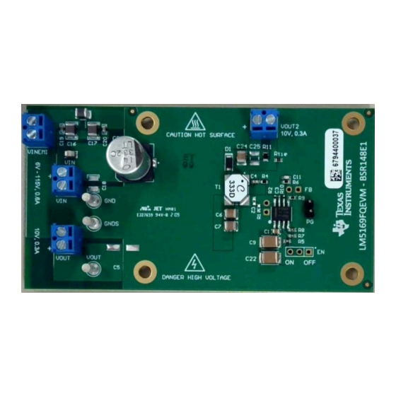
LM5169FQEVM Evaluation Module 3.2 Detailed Descriptions This section describes the connectors and the test points on the EVM and how to properly connect, set up and use the LM5169FQEVM EVM. See Figure 3-1 for location of connectors and jumpers. VOUT Output voltage of the converter. -
Page 8: Schematic
Schematic www.ti.com 4 Schematic Figure 4-1. LM5169FQEVM EVM Schematic LM5169FQEVM EVM User Guide SNVU757 – JUNE 2021 Submit Document Feedback Copyright © 2021 Texas Instruments Incorporated... -
Page 9: Pcb Layout
1-oz copper mid-layer planes to dissipate heat with an array of thermal vias under the thermal pad to connect to all four layers. Figure 5-1. Top Layer Figure 5-2. Mid-Layer 1 Ground Plane SNVU757 – JUNE 2021 LM5169FQEVM EVM User Guide Submit Document Feedback Copyright © 2021 Texas Instruments Incorporated... -
Page 10: Figure 5-3. Mid-Layer2 Routing
PCB Layout www.ti.com Figure 5-3. Mid-Layer2 Routing Figure 5-4. Bottom Layer LM5169FQEVM EVM User Guide SNVU757 – JUNE 2021 Submit Document Feedback Copyright © 2021 Texas Instruments Incorporated... -
Page 11: Bill Of Materials
CAP, CERM, 1000 pF, 50 V, +/- 5%, C0603C102J5RACAUTO Kemet X7R, AEC-Q200 Grade 1, 0603 CAP, CERM, 4.7 uF, 100 V, +/- 10%, CGA6M3X7S2A475K200AB X7S, AEC-Q200 Grade 1, 1210 SNVU757 – JUNE 2021 LM5169FQEVM EVM User Guide Submit Document Feedback Copyright © 2021 Texas Instruments Incorporated... - Page 12 Grade 1, SMD RES, 1.0, 5%, 0.1 W, AEC-Q200 Grade CRCW06031R00JNEA Vishay-Dale 0, 0603 RES, 0.2, 1%, 1 W, 2010 CSRN2010FKR200 Stackpole Electronics Inc LM5169FQEVM EVM User Guide SNVU757 – JUNE 2021 Submit Document Feedback Copyright © 2021 Texas Instruments Incorporated...
-
Page 13: Performance Curves
= 48 V = 100 mA = 48 V = 100 mA OUT2 OUT2 Figure 7-5. Typical Start-up Waveform Figure 7-6. Typical Shut-down Waveform SNVU757 – JUNE 2021 LM5169FQEVM EVM User Guide Submit Document Feedback Copyright © 2021 Texas Instruments Incorporated... - Page 14 TI products. TI’s provision of these resources does not expand or otherwise alter TI’s applicable warranties or warranty disclaimers for TI products. TI objects to and rejects any additional or different terms you may have proposed. IMPORTANT NOTICE Mailing Address: Texas Instruments, Post Office Box 655303, Dallas, Texas 75265 Copyright © 2022, Texas Instruments Incorporated...