Table of Contents
Advertisement
Quick Links
With input voltage range and current capability as specified in
converters from TI provides flexibility, scalability, and optimized solution size for a range of applications.
Using an 8-pin WSON package with 4-mm × 4-mm footprint and 0.8-mm pin pitch, these converters
enable isolated DC/DC solutions with high density and low component count.
PSR FLYBACK
INPUT VOLTAGE
CONVERTER
RANGE
LM5181-Q1
4.5 V to 65 V
LM5180-Q1
4.5 V to 65 V
LM25180-Q1
4.5 V to 42 V
LM25183-Q1
4.5 V to 42 V
LM25184-Q1
4.5 V to 42 V
The
LM5180EVM-S05
regulation (PSR) based on sampling of the primary winding voltage of the transformer to achieve high
efficiency in a small footprint. It operates over a wide input voltage range of 10 V to 65 V, providing a
regulated 5-V output using a transformer with 3 : 1 turns ratio. Operating without an optocoupler or
transformer auxiliary winding, the converter delivers an output voltage with ±1.5% regulation.
The EVM design uses the
MOSFET provides ample margin for line transients and switch (SW) node voltage spikes related to
transformer parasitic leakage inductance. Load regulation errors related to transformer secondary winding
resistance are avoided by virtue of the quasi-resonant boundary conduction mode (BCM) control scheme.
Additional features includes current-mode control with internal compensation, hiccup-mode fault
protection, programmable soft-start, and optional output voltage temperature compensation. Input UVLO
protects the converter at low input voltage conditions, and the EN/UVLO pin supports adjustable UVLO
with user-defined hysteresis for application specific power-up and power-down requirements.
The LM(2)5180 and LM(2)5180-Q1 converters are available in a 8-pin WSON package with 4-mm × 4-mm
footprint and 0.8-mm pin pitch to enable isolated DC/DC solutions with high density and low component
count. Wettable flank pins provide a visual indicator of solderability, which reduces inspection time and
manufacturing costs in high-reliability industrial and automotive applications. See the
LM5180-Q1
data sheets for more information. Use the LM5180-Q1 with
create a custom regulator design. Furthermore, you can download the
optimize component values and examine predicted efficiency performance across line and load ranges.
1
1.1
1.2
Features and Electrical Performance
2
3
....................................................................................................................
4
5
5.1
5.2
5.3
LM5180-Q1 Single-Output EVM User's Guide
Table 1. PSR Flyback DC/DC Converter Family
PEAK SWITCH
CURRENT (TYP)
0.75 A
1.5 A
1.5 A
2.5 A
4.1 A
evaluation module (EVM) is a flyback DC/DC converter that employs primary-side
LM5180-Q1
65-V PSR flyback converter. An integrated 100-V, 1.5-A power
.............................................................................................
................................................................................................
.........................................................................................
.................................................................................................
..................................................................................................
...........................................................................................................
.....................................................................................................
........................................................................................
Copyright © 2018-2020, Texas Instruments Incorporated
SNVU592D - July 2018 - Revised April 2020
Table
1, the family of PSR flyback DC/DC
MAXIMUM LOAD CURRENT, V
V
= 4.5 V
V
IN
IN
90 mA
180 mA
180 mA
360 mA
180 mA
360 mA
300 mA
600 mA
500 mA
1 A
Contents
............................................................................
LM5180-Q1 Single-Output EVM User's Guide
User's Guide
= 12 V, N
= 1
OUT
PS
= 13.5 V
V
= 24 V
IN
225 mA
450 mA
450 mA
750 mA
1.25 A
LM5180
WEBENCH
Power Designer
®
LM5180 Quickstart Calculator
and
to
to
3
3
3
4
5
5
6
6
7
7
1
Advertisement
Table of Contents

Related Manuals for Texas Instruments LM5180-Q1


Summary of Contents for Texas Instruments LM5180-Q1
-
Page 1: Table Of Contents
Wettable flank pins provide a visual indicator of solderability, which reduces inspection time and manufacturing costs in high-reliability industrial and automotive applications. See the LM5180 LM5180-Q1 data sheets for more information. Use the LM5180-Q1 with WEBENCH Power Designer ®... - Page 2 EVM Connections ......................Bill of Materials Trademarks WEBENCH is a registered trademark of Texas Instruments. All other trademarks are the property of their respective owners. LM5180-Q1 Single-Output EVM User's Guide SNVU592D – July 2018 – Revised April 2020 Submit Documentation Feedback...
-
Page 3: High Density Evm Description
High Density EVM Description The LM5180-Q1 single-output EVM is designed to use a regulated or non-regulated high-voltage input rail ranging from 10 V to 65 V to produce a tightly-regulated, isolated output voltage of 5 V at load currents of 1 A (or higher depending on V ). -
Page 4: Evm Performance Characteristics
The default output voltage of this single-output EVM is 5 V. Efficiency and other performance metrics can change based on operating input voltage, load current, externally-connected output capacitance, and other parameters. The maximum output power delivered by the LM5180-Q1 PSR flyback converter increases with input voltage. The selected flyback transformer provides functional isolation to 1500 V DC. -
Page 5: Application Circuit Diagram
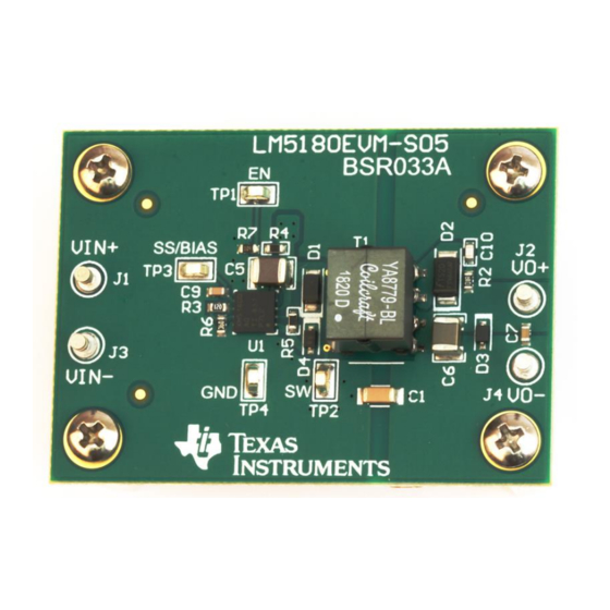
158 k: RSET SS/BIAS 130 k: 12.1 k: 47 nF Copyright © 2018, Texas Instruments Incorporated Figure 1. LM5180 PSR Flyback Converter Simplified Schematic EVM Photo Figure 2. EVM Photo (Top Side), 50 mm × 35 mm CAUTION Caution Hot surface. -
Page 6: Test Setup And Procedure
LM5180 Quickstart Calculator, and WEBENCH® Power Designer for additional guidance pertaining to component selection and converter operation. LM5180-Q1 Single-Output EVM User's Guide SNVU592D – July 2018 – Revised April 2020 Submit Documentation Feedback Copyright © 2018–2020, Texas Instruments Incorporated... -
Page 7: Test Equipment
• Decrease load to 0 A. Decrease input source voltage to 0 V. SNVU592D – July 2018 – Revised April 2020 LM5180-Q1 Single-Output EVM User's Guide Submit Documentation Feedback Copyright © 2018–2020, Texas Instruments Incorporated... -
Page 8: Test Data And Performance Curves
= 24V = 36V = 48V = 65V 0.001 0.01 Output Current (A) Figure 5. Conversion Efficiency (Log Scale) LM5180-Q1 Single-Output EVM User's Guide SNVU592D – July 2018 – Revised April 2020 Submit Documentation Feedback Copyright © 2018–2020, Texas Instruments Incorporated... -
Page 9: Load Regulation
= 24V = 36V = 48V = 65V 0.001 0.01 Output Current (A) Figure 7. Load Regulation (Log Scale) SNVU592D – July 2018 – Revised April 2020 LM5180-Q1 Single-Output EVM User's Guide Submit Documentation Feedback Copyright © 2018–2020, Texas Instruments Incorporated... -
Page 10: Operating Waveforms
= 1 A SW 20V/DIV 1 Ps/DIV Figure 9. SW Node Voltage, V = 48 V, I = 1 A LM5180-Q1 Single-Output EVM User's Guide SNVU592D – July 2018 – Revised April 2020 Submit Documentation Feedback Copyright © 2018–2020, Texas Instruments Incorporated... -
Page 11: Load Transient Response
The internal soft-start timer is applicable here as the SS capacitor was not installed during these start-up tests. SNVU592D – July 2018 – Revised April 2020 LM5180-Q1 Single-Output EVM User's Guide Submit Documentation Feedback Copyright © 2018–2020, Texas Instruments Incorporated... -
Page 12: Enable On
VOUT 1V/DIV IOUT 500mA/DIV 2 ms/DIV Figure 12. Enable On, V = 24 V, I = 1 A LM5180-Q1 Single-Output EVM User's Guide SNVU592D – July 2018 – Revised April 2020 Submit Documentation Feedback Copyright © 2018–2020, Texas Instruments Incorporated... -
Page 13: Cispr 25 Emi
Figure 13 Figure 14 present the EMI performance of the LM5180-Q1 EVM at 12-V and 24-V inputs, respectively. Conducted emissions are measured over a frequency range of 150 kHz to 108 MHz using a 5-µH LISN according to the CISPR 25 specification. CISPR 25 class 5 peak and average limit lines are denoted in red. -
Page 14: Cispr 25 Class 5 Radiated Emissions Plot
Frequency in Hz Figure 15. CISPR 25 Class 5 Radiated Emissions Plot, V = 13.5 V, I = 0.5 A LM5180-Q1 Single-Output EVM User's Guide SNVU592D – July 2018 – Revised April 2020 Submit Documentation Feedback Copyright © 2018–2020, Texas Instruments Incorporated... -
Page 15: Snvu592D - July 2018 - Revised April 2020
RSET SS/BIAS LM5180QNGURQ1 100k 12.1k 0.047uF Copyright © 2018, Texas Instruments Incorporated Figure 16. PSR Flyback EVM Schematic SNVU592D – July 2018 – Revised April 2020 LM5180-Q1 Single-Output EVM User's Guide Submit Documentation Feedback Copyright © 2018–2020, Texas Instruments Incorporated... -
Page 16: Bill Of Materials
Turret, PTH, 4.72 mm, VIN+, VIN–, VOUT+, VOUT– 1573-2 Keystone Electronics TP1, TP2, TP3, Test point for EN, SW, SS/BIAS, GND 5015 Keystone Electronics LM5180-Q1 Single-Output EVM User's Guide SNVU592D – July 2018 – Revised April 2020 Submit Documentation Feedback Copyright © 2018–2020, Texas Instruments Incorporated... -
Page 17: Pcb Layout
VIN+, VIN–, VOUT+ and VOUT–. Figure 17. Top Copper (Top View) Figure 18. Bottom Copper (Top View) SNVU592D – July 2018 – Revised April 2020 LM5180-Q1 Single-Output EVM User's Guide Submit Documentation Feedback Copyright © 2018–2020, Texas Instruments Incorporated... -
Page 18: Assembly Drawings
EVM Documentation www.ti.com Assembly Drawings Figure 19. Top Component Drawing Figure 20. Bottom Component Drawing LM5180-Q1 Single-Output EVM User's Guide SNVU592D – July 2018 – Revised April 2020 Submit Documentation Feedback Copyright © 2018–2020, Texas Instruments Incorporated... -
Page 19: Layout Design Tips For A Single-Output Psr Flyback Converter
Figure 21. Layout Design Tips for a Single-output PSR Flyback Converter SNVU592D – July 2018 – Revised April 2020 LM5180-Q1 Single-Output EVM User's Guide Submit Documentation Feedback Copyright © 2018–2020, Texas Instruments Incorporated... -
Page 20: Device And Documentation Support
, Low EMI Synchronous Buck Circuits for Cost-driven, Demanding Applications (SLYY104) – An Overview of Conducted EMI Specifications for Power Supplies (SLYY136) LM5180-Q1 Single-Output EVM User's Guide SNVU592D – July 2018 – Revised April 2020 Submit Documentation Feedback Copyright © 2018–2020, Texas Instruments Incorporated... - Page 21 (SNVA719) • PowerPAD Thermally Enhanced Package (SLMA002) • PowerPAD Made Easy (SLMA004) • Using New Thermal Metrics (SBVA025) SNVU592D – July 2018 – Revised April 2020 LM5180-Q1 Single-Output EVM User's Guide Submit Documentation Feedback Copyright © 2018–2020, Texas Instruments Incorporated...
-
Page 22: A, (A) 150 Khz To 30 Mhz, (B)
Changes from Original (July 2018) to A Revision ......................Page ....................... • Changed photo in Figure 2 ........................• Added new waveforms Revision History SNVU592D – July 2018 – Revised April 2020 Submit Documentation Feedback Copyright © 2018–2020, Texas Instruments Incorporated... - Page 23 STANDARD TERMS FOR EVALUATION MODULES Delivery: TI delivers TI evaluation boards, kits, or modules, including any accompanying demonstration software, components, and/or documentation which may be provided together or separately (collectively, an “EVM” or “EVMs”) to the User (“User”) in accordance with the terms set forth herein.
- Page 24 www.ti.com Regulatory Notices: 3.1 United States 3.1.1 Notice applicable to EVMs not FCC-Approved: FCC NOTICE: This kit is designed to allow product developers to evaluate electronic components, circuitry, or software associated with the kit to determine whether to incorporate such items in a finished product and software developers to write software applications for use with the end product.
- Page 25 www.ti.com Concernant les EVMs avec antennes détachables Conformément à la réglementation d'Industrie Canada, le présent émetteur radio peut fonctionner avec une antenne d'un type et d'un gain maximal (ou inférieur) approuvé pour l'émetteur par Industrie Canada. Dans le but de réduire les risques de brouillage radioélectrique à...
- Page 26 www.ti.com EVM Use Restrictions and Warnings: 4.1 EVMS ARE NOT FOR USE IN FUNCTIONAL SAFETY AND/OR SAFETY CRITICAL EVALUATIONS, INCLUDING BUT NOT LIMITED TO EVALUATIONS OF LIFE SUPPORT APPLICATIONS. 4.2 User must read and apply the user guide and other available documentation provided by TI regarding the EVM prior to handling or using the EVM, including without limitation any warning or restriction notices.
- Page 27 Notwithstanding the foregoing, any judgment may be enforced in any United States or foreign court, and TI may seek injunctive relief in any United States or foreign court. Mailing Address: Texas Instruments, Post Office Box 655303, Dallas, Texas 75265 Copyright © 2019, Texas Instruments Incorporated...
- Page 28 TI products. TI’s provision of these resources does not expand or otherwise alter TI’s applicable warranties or warranty disclaimers for TI products. Mailing Address: Texas Instruments, Post Office Box 655303, Dallas, Texas 75265 Copyright © 2020, Texas Instruments Incorporated...