Table of Contents
Advertisement
Quick Links
www.ti.com
EVM User's Guide: LM5185EVM-SIO
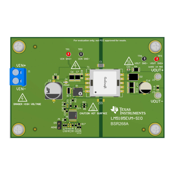
LM5185-Q1 Single-Isolated-Output Evaluation Module
Description
The LM5185-Q1 controller uses an external power
MOSFET and has adjustable loop compensation and
current limit. All these features bring flexibility and
design optimization for power scaling, transformer
design, and BOM optimization, as well as
overall performance and solution cost. Other user
programmabilities are also supported including
the input UVLO with hysteresis, soft-start, and
temperature compensation.
Get Started
1. Order the EVM at ti.com.
2. Read this user's guide carefully.
3. Prepare the bench setup per instructions. Take
cautions to prevent damage by ESD when
handling the EVM.
4. Power up the EVM by following the recommended
steps.
5. Run tests and measurements. Take cautions of
high voltage and hot temperature produced by the
EVM during test.
SNVU869 – AUGUST 2023
Submit Document Feedback
Features
•
Wide input voltage range (default 20V to 60V,
extendable 6V to 90V)
•
Tight voltage regulation of the isolated output
without opto-coupler: 16.4V ±1.5%
•
Removal of the opto-coupler and transformer aux
winding saves solution size and cost.
•
Peak conversion efficiency > 90%
•
Programmable loop compensation, current limit,
input UVLO, and thermal compensation allowing
for flexible and optimal designs.
Applications
•
Traction inverters
•
Onboard charger (OBC)
•
HEV/EV HVAC and heater
•
Micro inverters
•
Motor drives
•
Battery Management Systems (BMS)
•
Generic
•
PoE PD dc-dc converters
•
Generic isolated bias power rails for industrial and
telecom systems
Copyright © 2023 Texas Instruments Incorporated
IGBT, MOSFET, GaN and SiC gate drivers
LM5185-Q1 Single-Isolated-Output Evaluation Module
Description
1
Advertisement
Table of Contents

Related Manuals for Texas Instruments LM5185-Q1


Summary of Contents for Texas Instruments LM5185-Q1
- Page 1 Description EVM User's Guide: LM5185EVM-SIO LM5185-Q1 Single-Isolated-Output Evaluation Module Description Features The LM5185-Q1 controller uses an external power • Wide input voltage range (default 20V to 60V, MOSFET and has adjustable loop compensation and extendable 6V to 90V) current limit. All these features bring flexibility and •...
-
Page 2: Kit Contents
(SIO) evaluational module (EVM), otherwise known as LM5185EVM-SIO, is designed to demonstrate the features and functionality of the LM5185-Q1 device. The device is a 100-V Primary-Side-Regulated (PSR) flyback DC/DC controller based on sampling the primary winding voltage of the transformer to achieve tight output regulation and high efficiency, without using the opto coupler nor tertiary bias winding like in a conventional flyback converter. -
Page 3: Device Information
6 V with derated output current of 0.4A by changing the EN/UVLO set point. Further lower input voltage down to 4.5V is supported by the LM5185-Q1 but the EVM requires a different transformer. However, the maximum V voltage of the EVM can be increased to 90 V if the power MOSFET is changed to a 150 V or higher rated device, and if the input bulk capacitor is replaced with at least a 100 V rated part. -
Page 4: Header Information
Primary side power ground reference. J5-1 EN/UVLO Enable and UVLO control signal. Closing J5-1 and J5-2 disables the EVM. J5-2 AGND Analog signal reference ground. LM5185-Q1 Single-Isolated-Output Evaluation Module SNVU869 – AUGUST 2023 Submit Document Feedback Copyright © 2023 Texas Instruments Incorporated... -
Page 5: Best Practices
PCB as marked by the hot surface symbols. Please read the following notices carefully. WARNING SNVU869 – AUGUST 2023 LM5185-Q1 Single-Isolated-Output Evaluation Module Submit Document Feedback Copyright © 2023 Texas Instruments Incorporated... - Page 6 AC power supply or a high-voltage DC supply. Please read this user guide and the safety- related documents that come with the EVM package before operating this EVM. LM5185-Q1 Single-Isolated-Output Evaluation Module SNVU869 – AUGUST 2023 Submit Document Feedback Copyright © 2023 Texas Instruments Incorporated...
- Page 7 High Voltage! Electric shock is possible when connecting board to live wire. Board must be handled with care by a professional. For safety, use of isolated test equipment with overvoltage and overcurrent protection is highly recommended. SNVU869 – AUGUST 2023 LM5185-Q1 Single-Isolated-Output Evaluation Module Submit Document Feedback Copyright © 2023 Texas Instruments Incorporated...
- Page 8 = 60 V 0.6% 0.4% 0.2% -0.2% -0.4% -0.6% -0.8% Load Current (A) Figure 3-2. EVM Output Voltage Regulation vs Load and Input Voltage LM5185-Q1 Single-Isolated-Output Evaluation Module SNVU869 – AUGUST 2023 Submit Document Feedback Copyright © 2023 Texas Instruments Incorporated...
- Page 9 C1=Vin; C2=Vout; C3=COMP; C4=SW Figure 3-3. Start-up Under No Load: Vin=24V, Iout=0A C1=Vin; C2=Vout; C3=COMP; C4=SW Figure 3-4. Start-up Under Full Load: Vin=24V, Iout=1A SNVU869 – AUGUST 2023 LM5185-Q1 Single-Isolated-Output Evaluation Module Submit Document Feedback Copyright © 2023 Texas Instruments Incorporated...
- Page 10 Figure 3-5. Load Transient Response: Vin=24V, 0.625A to 1.25A Load Transients 3.1.3.3 Switching C1=SW; C2=Vsec; C4=Vcomp Figure 3-6. FFM Operation: VIN=48 V, Iout= 0.1A LM5185-Q1 Single-Isolated-Output Evaluation Module SNVU869 – AUGUST 2023 Submit Document Feedback Copyright © 2023 Texas Instruments Incorporated...
- Page 11 Implementation Results C1=SW; C2=Vsec; C4=Vcomp Figure 3-7. DCM Operation: Vin=48V, Iout=0.5A Figure 3-8. BCM Operation: Vin=48V, Iout=1.0A SNVU869 – AUGUST 2023 LM5185-Q1 Single-Isolated-Output Evaluation Module Submit Document Feedback Copyright © 2023 Texas Instruments Incorporated...
-
Page 12: Thermal Performance
Implementation Results www.ti.com 3.2 Thermal Performance Figure 3-9. EVM Thermal Image. Vin=48V, Iout=1.0A LM5185-Q1 Single-Isolated-Output Evaluation Module SNVU869 – AUGUST 2023 Submit Document Feedback Copyright © 2023 Texas Instruments Incorporated... - Page 13 AGND 100pF 0.02 PGND 294k LM5185-Q1 Net-Tie 16.9k 12.1k 10.0k 1000pF 47pF 0.1uF 0.1uF PGND 0.022uF AGND PGND AGND Figure 4-1. LM5185EVM-SIO Schematic SNVU869 – AUGUST 2023 LM5185-Q1 Single-Isolated-Output Evaluation Module Submit Document Feedback Copyright © 2023 Texas Instruments Incorporated...
- Page 14 EVM. Figure 4-2. Top Layer Silkscreen (Top View) Figure 4-3. Top Layer Layout (Top View) LM5185-Q1 Single-Isolated-Output Evaluation Module SNVU869 – AUGUST 2023 Submit Document Feedback Copyright © 2023 Texas Instruments Incorporated...
- Page 15 Hardware Design Files Figure 4-4. Mid Layer 1 Layout (Top View) Figure 4-5. Mid Layer 2 Layout (Top View) SNVU869 – AUGUST 2023 LM5185-Q1 Single-Isolated-Output Evaluation Module Submit Document Feedback Copyright © 2023 Texas Instruments Incorporated...
- Page 16 Hardware Design Files www.ti.com Figure 4-6. Bottom Layer Layout (Bottom View) Figure 4-7. Bottom Layer Silkscreen (Bottom View) LM5185-Q1 Single-Isolated-Output Evaluation Module SNVU869 – AUGUST 2023 Submit Document Feedback Copyright © 2023 Texas Instruments Incorporated...
-
Page 17: Bill Of Materials (Bom)
RES, 16.9 k, 1%, 0.1 W, 0603 RC0603FR-0716K9L Yageo RES, 12.1 k, 1%, 0.1 W, 0603 RC0603FR-0712K1L Yageo RES, 10.0 k, 1%, 0.1 W, 0603 RC0603FR-0710KL Yageo SNVU869 – AUGUST 2023 LM5185-Q1 Single-Isolated-Output Evaluation Module Submit Document Feedback Copyright © 2023 Texas Instruments Incorporated... -
Page 18: Additional Information
LM5185EVM-SIO EU Declaration of Conformity (DoC) for Restricting the Use of Hazardous Substances (RoHS) (SSZQR78) 6 Additional Information 6.1 Trademarks All trademarks are the property of their respective owners. LM5185-Q1 Single-Isolated-Output Evaluation Module SNVU869 – AUGUST 2023 Submit Document Feedback Copyright © 2023 Texas Instruments Incorporated... - Page 19 STANDARD TERMS FOR EVALUATION MODULES Delivery: TI delivers TI evaluation boards, kits, or modules, including any accompanying demonstration software, components, and/or documentation which may be provided together or separately (collectively, an “EVM” or “EVMs”) to the User (“User”) in accordance with the terms set forth herein.
- Page 20 www.ti.com Regulatory Notices: 3.1 United States 3.1.1 Notice applicable to EVMs not FCC-Approved: FCC NOTICE: This kit is designed to allow product developers to evaluate electronic components, circuitry, or software associated with the kit to determine whether to incorporate such items in a finished product and software developers to write software applications for use with the end product.
- Page 21 www.ti.com Concernant les EVMs avec antennes détachables Conformément à la réglementation d'Industrie Canada, le présent émetteur radio peut fonctionner avec une antenne d'un type et d'un gain maximal (ou inférieur) approuvé pour l'émetteur par Industrie Canada. Dans le but de réduire les risques de brouillage radioélectrique à...
- Page 22 www.ti.com EVM Use Restrictions and Warnings: 4.1 EVMS ARE NOT FOR USE IN FUNCTIONAL SAFETY AND/OR SAFETY CRITICAL EVALUATIONS, INCLUDING BUT NOT LIMITED TO EVALUATIONS OF LIFE SUPPORT APPLICATIONS. 4.2 User must read and apply the user guide and other available documentation provided by TI regarding the EVM prior to handling or using the EVM, including without limitation any warning or restriction notices.
- Page 23 Notwithstanding the foregoing, any judgment may be enforced in any United States or foreign court, and TI may seek injunctive relief in any United States or foreign court. Mailing Address: Texas Instruments, Post Office Box 655303, Dallas, Texas 75265 Copyright © 2023, Texas Instruments Incorporated...
- Page 24 TI products. TI’s provision of these resources does not expand or otherwise alter TI’s applicable warranties or warranty disclaimers for TI products. TI objects to and rejects any additional or different terms you may have proposed. IMPORTANT NOTICE Mailing Address: Texas Instruments, Post Office Box 655303, Dallas, Texas 75265 Copyright © 2023, Texas Instruments Incorporated...