Table of Contents
Advertisement
Quick Links
LM5000EVAL Non-Isolated Flyback Evaluation Module
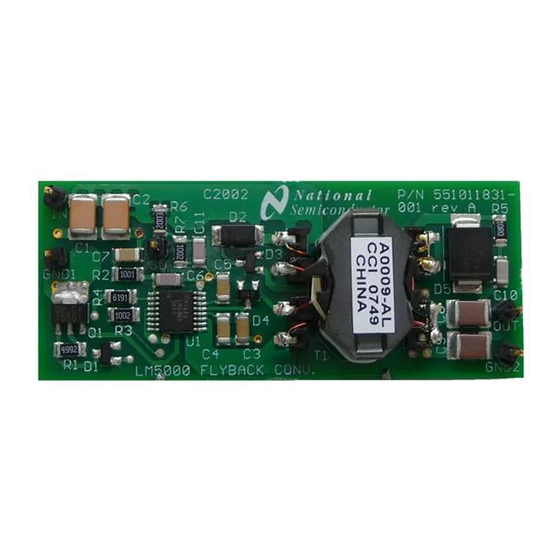
The LM5000EVAL evaluation module (EVM) provides the design engineer with a fully functional non-
isolated flyback converter to evaluate the LM5000-3 high-voltage switch-mode regulator integrated circuit
(IC). The EVM provides 3.3-V output with 2-A current capability. The input voltage range is from 20 V to
55 V. This user's guide contains the electrical specification, quick setup procedure, performance curves,
application schematic, and bill of materials (BOM).
...................................................................................................................
1
....................................................................................................................
2
2.1
2.2
3
Performance Curves
.....................................................................................................................
4
Schematic
.........................................................................................................................
5
Layout
6
1
Efficiency with Respect to Load Current
2
Turn-On Waveforms (VIN = 36 V, IOUT = 2 A)
3
4
Load Transient Response (VIN = 36 V)
5
Non-Isolated Flyback Converter Schematic
6
.....................................................................................................................
7
8
1
2
3
SNVU452 - July 2014
Submit Documentation Feedback
............................................................................................
........................................................................................................
...............................................................................................................
..................................................................................
..................................................................................
...............................................................................................................
.................................................................................................................
...............................................................................................
................................................................................................
.......................................................................................
Copyright © 2014, Texas Instruments Incorporated
Contents
.........................................................................
List of Figures
..........................................................................
........................................................................
..............................................................................
List of Tables
LM5000EVAL Non-Isolated Flyback Evaluation Module User's Guide
User's Guide
SNVU452 - July 2014
User's Guide
2
2
2
2
3
5
6
7
3
3
4
4
5
6
6
6
2
2
7
1
Advertisement
Table of Contents

Related Manuals for Texas Instruments LM5000EVAL


Summary of Contents for Texas Instruments LM5000EVAL
-
Page 1: Table Of Contents
LM5000EVAL Non-Isolated Flyback Evaluation Module User’s Guide The LM5000EVAL evaluation module (EVM) provides the design engineer with a fully functional non- isolated flyback converter to evaluate the LM5000-3 high-voltage switch-mode regulator integrated circuit (IC). The EVM provides 3.3-V output with 2-A current capability. The input voltage range is from 20 V to 55 V. -
Page 2: Introduction
Step 6. Turn off the load, and decrease the input voltage down to 0 V to shut down the flyback converter, and then turn on the load to discharge the output capacitors. LM5000EVAL Non-Isolated Flyback Evaluation Module User’s Guide SNVU452 – July 2014 Submit Documentation Feedback Copyright ©... - Page 3 Figure 1. Efficiency with Respect to Load Current Figure 2. Turn-On Waveforms (VIN = 36 V, IOUT = 2 A) SNVU452 – July 2014 LM5000EVAL Non-Isolated Flyback Evaluation Module User’s Guide Submit Documentation Feedback Copyright © 2014, Texas Instruments Incorporated...
-
Page 4: Output Voltage Ripple (Vin = 36 V, Iout = 2 A)
Figure 3. Output Voltage Ripple (VIN = 36 V, IOUT = 2 A) Figure 4. Load Transient Response (VIN = 36 V) LM5000EVAL Non-Isolated Flyback Evaluation Module User’s Guide SNVU452 – July 2014 Submit Documentation Feedback Copyright © 2014, Texas Instruments Incorporated... - Page 5 Schematic www.ti.com Schematic Figure 5 shows the LM5000EVAL EVM schematic. Figure 5. Non-Isolated Flyback Converter Schematic SNVU452 – July 2014 LM5000EVAL Non-Isolated Flyback Evaluation Module User’s Guide Submit Documentation Feedback Copyright © 2014, Texas Instruments Incorporated...
-
Page 6: Top Silkscreen
Layout www.ti.com Layout The printed-circuit board layout for the LM5000EVAL is shown in Figure 6 through Figure Figure 6. Top Silkscreen Figure 7. Top Layer Figure 8. Bottom Layer LM5000EVAL Non-Isolated Flyback Evaluation Module User’s Guide SNVU452 – July 2014 Submit Documentation Feedback Copyright ©... -
Page 7: Bill Of Materials
Bill of Materials www.ti.com Bill of Materials Table 3 presents the BOM for the LM5000EVAL EVM. Table 3. LM5000EVAL EVM Bill of Materials Item Part Number Description Value C4532X7R2A105MT Capacitor, CER, TDK 1 µF, 100 V C4532X7R2A105MT Capacitor, CER, TDK 1 µF, 100 V... - Page 8 ADDITIONAL TERMS AND CONDITIONS, WARNINGS, RESTRICTIONS, AND DISCLAIMERS FOR EVALUATION MODULES Texas Instruments Incorporated (TI) markets, sells, and loans all evaluation boards, kits, and/or modules (EVMs) pursuant to, and user expressly acknowledges, represents, and agrees, and takes sole responsibility and risk with respect to, the following: 1.
- Page 9 RADIO FREQUENCY REGULATORY COMPLIANCE INFORMATION FOR EVALUATION MODULES Texas Instruments Incorporated (TI) evaluation boards, kits, and/or modules (EVMs) and/or accompanying hardware that is marketed, sold, or loaned to users may or may not be subject to radio frequency regulations in specific countries.
- Page 10 Les types d'antenne non inclus dans cette liste, ou dont le gain est supérieur au gain maximal indiqué, sont strictement interdits pour l'exploitation de l'émetteur. Mailing Address: Texas Instruments, Post Office Box 655303, Dallas, Texas 75265 Copyright © 2014, Texas Instruments Incorporated spacer Important Notice for Users of EVMs Considered “Radio Frequency Products”...
- Page 11 IMPORTANT NOTICE Texas Instruments Incorporated and its subsidiaries (TI) reserve the right to make corrections, enhancements, improvements and other changes to its semiconductor products and services per JESD46, latest issue, and to discontinue any product or service per JESD48, latest issue.