Table of Contents
Advertisement
Quick Links
This user's guide describes the characteristics, operation, and use of the LM5108 Evaluation Module
(EVM). A complete schematic diagram, PCB layouts, and BOM are included in this document.
...................................................................................................................
1
....................................................................................................................
2
2.1
2.2
3
4
4.1
4.2
4.3
5
5.1
5.2
6
7
7.1
.....................................................................................................................
8
9
10
1
2
.......................................................................................................................
3
4
5
.................................................................................................................
6
...................................................................................................................
7
8
9
..................................................................................................................
10
11
1
2
3
4
SLUUC42 - January 2020
Submit Documentation Feedback
..............................................................................................................
......................................................................................................
.....................................................................................................
................................................................................................................
............................................................................................................
...........................................................................................................
....................................................................................................
...................................................................................
............................................................................................................
.........................................................................................................
L
................................................................................................
...........................................................................................................
.............................................................................................................
.................................................................................
..............................................................................................................
..............................................................................................................
....................................................................................................
...............................................................................................................
............................................................................................................
..............................................................................................................
....................................................................................................
.......................................................................................................
............................................................................................
Copyright © 2020, Texas Instruments Incorporated
Using the LM5108EVM
Contents
...............................................................................
.......................................................................
List of Figures
List of Tables
..............................................................................
User's Guide
SLUUC42 - January 2020
2
2
2
3
3
4
4
4
4
6
6
6
7
8
8
9
10
14
5
6
8
8
9
10
11
12
12
13
13
3
4
5
14
1
Using the LM5108EVM
Advertisement
Table of Contents

Related Manuals for Texas Instruments LM5108EVM


Summary of Contents for Texas Instruments LM5108EVM
-
Page 1: Table Of Contents
Top Image ......................Bottom Image List of Tables ....................Connection Descriptions ................Two-Channel Function Generator Settings ....................... Oscilloscope Settings .................... LM5108EVM List of Materials SLUUC42 – January 2020 Using the LM5108EVM Submit Documentation Feedback Copyright © 2020, Texas Instruments Incorporated... -
Page 2: Introduction
All trademarks are the property of their respective owners. Introduction The LM5108EVM is designed to primarily evaluate the LM5108 performance. This driver is a 100-V boot voltage, high-side, low-side driver with 1.5-A peak source and 2.5-A sink current for driving two N-Channel MOSFETs. -
Page 3: I/O Description
CAUTION The LM5108EVM is designed for low-voltage evaluation only, and is not certified for evaluation with voltages beyond the absolute maximums listed in the electrical specifications. Do not evaluate high-voltage parameters with this board. -
Page 4: Test Summary
Test Summary www.ti.com Test Summary Definitions This procedure details how to configure the LM5108EVM evaluation board. Within this test procedure, the following naming conventions are applied. Refer to the LM5108EVM Bench Setup Diagram and Configuration, Figure 1, for details. DMM: Digital multimeter... -
Page 5: Bench Setup Diagram And Configuration
Apply oscilloscope channel-2 probes on LO LD-GND, minimizing the loop area as much as possible. Oscilloscope Function Generator Power Supply #1 12V: DMM # 1 0.05A DC Current Figure 1. Bench Setup Diagram and Configuration SLUUC42 – January 2020 Using the LM5108EVM Submit Documentation Feedback Copyright © 2020, Texas Instruments Incorporated... -
Page 6: Power Up And Power Down Procedure
Power Down Use the following steps to power down the EVM: 1. Disable function generator 2. Disable power supply #1 3. Disconnect cables and probes Using the LM5108EVM SLUUC42 – January 2020 Submit Documentation Feedback Copyright © 2020, Texas Instruments Incorporated... -
Page 7: Operation With External Bootstrap Diode
Operation With External Bootstrap Diode The LM5108EVM has an internal bootstrap diode included, the series resistor (R10) is not populated. This allows the user to evaluate pin compatible drivers that do not have the internal bootstrap diode which is included with the LM5108 High-Side and Low-Side Driver. -
Page 8: Typical Performance Waveforms (C = 1000 Pf)
HO LD LO LD Figure 4. LI and LO Propagation Delay Waveforms (Green and Magenta are PWM Inputs, Yellow and Blue are Driver Outputs) Using the LM5108EVM SLUUC42 – January 2020 Submit Documentation Feedback Copyright © 2020, Texas Instruments Incorporated... -
Page 9: Schematic
Schematic www.ti.com Schematic Figure 5 shows the LM5108EVM schematic diagram. Figure 5. LM5108EVM Schematic U2 is not installed since it is an alternate driver IC used on a different board assembly variation. SLUUC42 – January 2020 Using the LM5108EVM Submit Documentation Feedback... -
Page 10: Layout Diagrams
Layout Diagrams www.ti.com Layout Diagrams The PCB layout information for LM5108EVM is shown in Figure 6 through Figure Figure 6. Top Overlay Using the LM5108EVM SLUUC42 – January 2020 Submit Documentation Feedback Copyright © 2020, Texas Instruments Incorporated... -
Page 11: Top Layer
Layout Diagrams www.ti.com Figure 7. Top Layer SLUUC42 – January 2020 Using the LM5108EVM Submit Documentation Feedback Copyright © 2020, Texas Instruments Incorporated... -
Page 12: Bottom Layer
Layout Diagrams www.ti.com Figure 8. Bottom Layer Figure 9. Bottom Overlay Using the LM5108EVM SLUUC42 – January 2020 Submit Documentation Feedback Copyright © 2020, Texas Instruments Incorporated... -
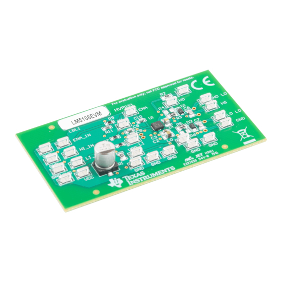
Page 13: Top Image
Layout Diagrams www.ti.com Figure 10. Top Image Figure 11. Bottom Image SLUUC42 – January 2020 Using the LM5108EVM Submit Documentation Feedback Copyright © 2020, Texas Instruments Incorporated... -
Page 14: List Of Materials
List of Materials www.ti.com List of Materials Table 4 lists the LM5108EVM list of materials. Table 4. LM5108EVM List of Materials Description Part Number Manufacturer CAP, AL, 47 µF, 50 V, ±20%, 0.68 ohm, SMD UUD1H470MCL1GS Nichicon CAP, CERM, 4.7 µF, 25 V,±10%, X7R, 0805 C2012X7R1E475K125AB CAP, CERM, 0.22 µF, 50 V,±10%, X7R, 0603... - Page 15 STANDARD TERMS FOR EVALUATION MODULES Delivery: TI delivers TI evaluation boards, kits, or modules, including any accompanying demonstration software, components, and/or documentation which may be provided together or separately (collectively, an “EVM” or “EVMs”) to the User (“User”) in accordance with the terms set forth herein.
- Page 16 www.ti.com Regulatory Notices: 3.1 United States 3.1.1 Notice applicable to EVMs not FCC-Approved: FCC NOTICE: This kit is designed to allow product developers to evaluate electronic components, circuitry, or software associated with the kit to determine whether to incorporate such items in a finished product and software developers to write software applications for use with the end product.
- Page 17 www.ti.com Concernant les EVMs avec antennes détachables Conformément à la réglementation d'Industrie Canada, le présent émetteur radio peut fonctionner avec une antenne d'un type et d'un gain maximal (ou inférieur) approuvé pour l'émetteur par Industrie Canada. Dans le but de réduire les risques de brouillage radioélectrique à...
- Page 18 www.ti.com EVM Use Restrictions and Warnings: 4.1 EVMS ARE NOT FOR USE IN FUNCTIONAL SAFETY AND/OR SAFETY CRITICAL EVALUATIONS, INCLUDING BUT NOT LIMITED TO EVALUATIONS OF LIFE SUPPORT APPLICATIONS. 4.2 User must read and apply the user guide and other available documentation provided by TI regarding the EVM prior to handling or using the EVM, including without limitation any warning or restriction notices.
- Page 19 Notwithstanding the foregoing, any judgment may be enforced in any United States or foreign court, and TI may seek injunctive relief in any United States or foreign court. Mailing Address: Texas Instruments, Post Office Box 655303, Dallas, Texas 75265 Copyright © 2019, Texas Instruments Incorporated...
- Page 20 TI products. TI’s provision of these resources does not expand or otherwise alter TI’s applicable warranties or warranty disclaimers for TI products. Mailing Address: Texas Instruments, Post Office Box 655303, Dallas, Texas 75265 Copyright © 2020, Texas Instruments Incorporated...