Table of Contents
Advertisement
Quick Links
www.ti.com
User's Guide
LM5169FQEVM EVM User Guide
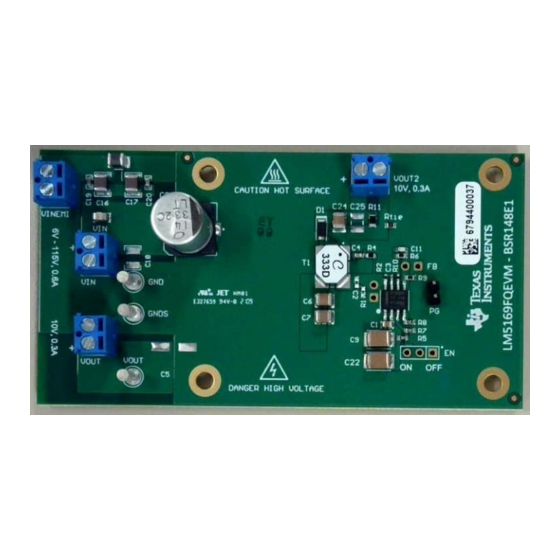
The LM5169FQEVM is a 115-V DC/DC fly-buck regulator that employs synchronous rectification to achieve
high conversion efficiency in a small footprint. The EVM operates over a wide input voltage range of 20 V to
115 V (120 V absolute maximum) to provide a regulated 10-V output, 0.3A at 750-kHz switching frequency,
and an additional 10-V, 0.3A floating output. The output voltage has better than 1.5% set-point accuracy
and is adjustable using an external resistor divider. The module design uses the LM5169F-Q1 synchronous
buck converter with wide input voltage range, wide duty-cycle range, integrated high-side and low-side power
MOSFETs, advanced over current protection, and precision enable. With AEC-Q100 grade 1 automotive
qualification, the LM5169F-Q1 is rated to operate over a junction temperature range of –40°C to +150°C.
Please note that for EVMs labeled as LM5168FQEVM, that the LM5168F is installed and approximately one half
of the load current is available from this device. Both EVMs are identical, except for the converter IC installed.
For the LM5169F version, please contact your local Texas Instruments representative.
EVM
LM5169FQEVM
LM5168FQEVM
SNVU757 – JUNE 2021
Submit Document Feedback
ABSTRACT
Table 1-1. EVM Configuration
CONVERTER IC
LM5169F-Q1
8-pin SO package with PowerPAD (4.89 mm × 3.90 mm)
LM5168F-Q1
8-pin SO package with PowerPAD (4.89 mm × 3.90 mm)
Copyright © 2021 Texas Instruments Incorporated
PACKAGE
LM5169FQEVM EVM User Guide
1
Advertisement
Table of Contents

Related Manuals for Texas Instruments LM5168FQEVM


Summary of Contents for Texas Instruments LM5168FQEVM
-
Page 1: Table 1-1. Evm Configuration
LM5169F-Q1 is rated to operate over a junction temperature range of –40°C to +150°C. Please note that for EVMs labeled as LM5168FQEVM, that the LM5168F is installed and approximately one half of the load current is available from this device. Both EVMs are identical, except for the converter IC installed. -
Page 2: Table Of Contents
Figure 5-4. Bottom Layer................................List of Tables Table 1-1. EVM Configuration..............................1 Table 2-1. LM5168FQEVM Electrical Performance Characteristics.................... Table 6-1. LM5168FQEVM Bill of Materials ..........................Trademarks PowerPAD ™ is a trademark of Texas Instruments. All trademarks are the property of their respective owners. -
Page 3: General Ti High Voltage Evaluation User Safety Guidelines
WARNING: While the EVM is energized, never touch the EVM or its electrical circuits as they could be at high voltages capable of causing electrical shock hazard. SNVU757 – JUNE 2021 LM5169FQEVM EVM User Guide Submit Document Feedback Copyright © 2021 Texas Instruments Incorporated... - Page 4 High Voltage! Electric shock is possible when connecting board to live wire. Board should be handled with care by a professional. For safety, use of isolated test equipment with overvoltage and overcurrent protection is highly recommended. LM5169FQEVM EVM User Guide SNVU757 – JUNE 2021 Submit Document Feedback Copyright © 2021 Texas Instruments Incorporated...
-
Page 5: Evm Characteristics
Unless otherwise specified the following condition apply: T = 25ºC, I = Primary output current, I OUT1 OUT2 Secondary output current. LM5168FQEVM; both EVMs are identical, except for the converter IC installed. Table 2-1. LM5168FQEVM Electrical Performance Characteristics Parameter Test Conditions UNITS... -
Page 6: Lm5169Fqevm Evaluation Module
Figure respectively. Please note that for EVMs labeled as LM5168FQEVM, that the LM5168F is installed and approximately one half of the load current is available from this device. Both EVMs are identical, except for the converter IC installed. 3.1 Quick Start Procedure 1. -
Page 7: Detailed Descriptions
PGOOD is an open-drain output that is tied to V through a 100k Ω, resistor R SNVU757 – JUNE 2021 LM5169FQEVM EVM User Guide Submit Document Feedback Copyright © 2021 Texas Instruments Incorporated... -
Page 8: Schematic
Schematic www.ti.com 4 Schematic Figure 4-1. LM5169FQEVM EVM Schematic LM5169FQEVM EVM User Guide SNVU757 – JUNE 2021 Submit Document Feedback Copyright © 2021 Texas Instruments Incorporated... -
Page 9: Pcb Layout
1-oz copper mid-layer planes to dissipate heat with an array of thermal vias under the thermal pad to connect to all four layers. Figure 5-1. Top Layer Figure 5-2. Mid-Layer 1 Ground Plane SNVU757 – JUNE 2021 LM5169FQEVM EVM User Guide Submit Document Feedback Copyright © 2021 Texas Instruments Incorporated... -
Page 10: Figure 5-3. Mid-Layer2 Routing
PCB Layout www.ti.com Figure 5-3. Mid-Layer2 Routing Figure 5-4. Bottom Layer LM5169FQEVM EVM User Guide SNVU757 – JUNE 2021 Submit Document Feedback Copyright © 2021 Texas Instruments Incorporated... -
Page 11: Bill Of Materials
6 Bill of Materials Please note that for EVMs labeled as LM5168FQEVM, that the LM5168F is installed and approximately one half of the load current is available from this device. Both EVMs are identical, except for the converter IC installed. - Page 12 Bill of Materials www.ti.com Table 6-1. LM5168FQEVM Bill of Materials (continued) Designator Quantity Description PartNumber Manufacturer CAP, CERM, 22 µF, 25 V,+/- 10%, X5R, GRT32ER61E226KE13L MuRata AEC-Q200 Grade 3, 1210 J1, J5 Header, 100mil, 2x1, Gold, TH TSW-102-07-G-S Samtec Header, 100mil, 3x1, Gold, TH...
-
Page 13: Performance Curves
OUT1 OUT2 Secondary output current. Please note that for EVMs labeled as LM5168FQEVM, that the LM5168F is installed and approximately one half of the load current is available from this device. Both EVMs are identical, except for the converter IC installed. - Page 14 STANDARD TERMS FOR EVALUATION MODULES Delivery: TI delivers TI evaluation boards, kits, or modules, including any accompanying demonstration software, components, and/or documentation which may be provided together or separately (collectively, an “EVM” or “EVMs”) to the User (“User”) in accordance with the terms set forth herein.
- Page 15 www.ti.com Regulatory Notices: 3.1 United States 3.1.1 Notice applicable to EVMs not FCC-Approved: FCC NOTICE: This kit is designed to allow product developers to evaluate electronic components, circuitry, or software associated with the kit to determine whether to incorporate such items in a finished product and software developers to write software applications for use with the end product.
- Page 16 www.ti.com Concernant les EVMs avec antennes détachables Conformément à la réglementation d'Industrie Canada, le présent émetteur radio peut fonctionner avec une antenne d'un type et d'un gain maximal (ou inférieur) approuvé pour l'émetteur par Industrie Canada. Dans le but de réduire les risques de brouillage radioélectrique à...
- Page 17 www.ti.com EVM Use Restrictions and Warnings: 4.1 EVMS ARE NOT FOR USE IN FUNCTIONAL SAFETY AND/OR SAFETY CRITICAL EVALUATIONS, INCLUDING BUT NOT LIMITED TO EVALUATIONS OF LIFE SUPPORT APPLICATIONS. 4.2 User must read and apply the user guide and other available documentation provided by TI regarding the EVM prior to handling or using the EVM, including without limitation any warning or restriction notices.
- Page 18 Notwithstanding the foregoing, any judgment may be enforced in any United States or foreign court, and TI may seek injunctive relief in any United States or foreign court. Mailing Address: Texas Instruments, Post Office Box 655303, Dallas, Texas 75265 Copyright © 2019, Texas Instruments Incorporated...
- Page 19 TI products. TI’s provision of these resources does not expand or otherwise alter TI’s applicable warranties or warranty disclaimers for TI products.IMPORTANT NOTICE Mailing Address: Texas Instruments, Post Office Box 655303, Dallas, Texas 75265 Copyright © 2021, Texas Instruments Incorporated...