
Related Manuals for Jet JDP-15F


Summary of Contents for Jet JDP-15F
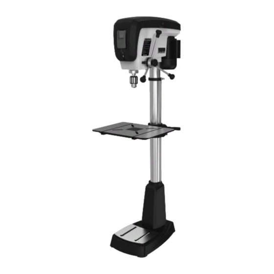
- Page 1 Operating Instructions and Parts Manual 16-speed Woodworking Drill Press Models JDP-15F, JDP-15B...
-
Page 2: Important Safety Instructions
Do not use this drill press for other than its binding of moving parts, breakage of parts, intended use. If used for other purposes, JET mounting and any other conditions that may disclaims any real or implied warranty and holds affect its operation. -
Page 3: About This Manual
4.0 About this manual This manual is provided by JET, covering the safe operation and maintenance procedures for a JET Model JDP- 15F and JDP-15B Drill Press. This manual contains instructions on installation, safety precautions, general operating procedures, maintenance instructions and parts breakdown. Your machine has been designed and constructed to provide consistent, long-term operation if used in accordance with the instructions as set forth in this document. -
Page 4: Specifications
5.0 Specifications Model number ............... JDP-15F ............. JDP-15B Stock number ................716250 ............716200 Style ................. Floor mount ..........Bench mount Motor and electricals: Motor type………………………………………totally enclosed fan cooled, induction, capacitor start ....Horsepower ................3/4 HP ............3/4 HP Phase .................. - Page 5 Figure 1: Base mounting holes The specifications in this manual were current at time of publication, but because of our policy of continuous improvement, JET reserves the right to change specifications at any time and without prior notice, without incurring obligations.
-
Page 6: Setup And Assembly
6.2 Shipping contents and make certain that all items are accounted for before discarding any packing material. Report any shortages or shipping damage to your JET distributor. Exposed metal surfaces on the drill press have been factory-coated with a protectant. - Page 7 6.4 Location The drill press should be placed in a dry area, with a level floor and good lighting. Provide enough space around drill press to allow for operations and any adjustments or servicing. 6.5 Assembly Do not connect drill press to power source until machine has been fully assembled.
- Page 8 Figure 9 The head assembly is heavy! To avoid injury and/or damage to equipment, lift the head onto the column only with additional assistance! 15. With the aid of a second person, carefully lift the head assembly and place it onto the column. Slide head down as far as it will go.
-
Page 9: Electrical Connections
The JDP-15F/15B drill press is rated at 115V power only, and comes with a plug designed for use on a In Canada, the use of a temporary adaptor is not circuit with a grounded outlet that looks like the one permitted by the Canadian Electrical Code, C22.1. -
Page 10: Extension Cords
Figure 14 Figure 13 8.2.2 Table repositioning 7.2 Extension cords Refer to Figure 14. The use of extension cords is discouraged; try to When drilling into a long workpiece, swing table out position equipment near the power source. If an of the way and use drill press base as your table. -
Page 11: Chuck And Arbor Removal
8.5 Chuck and arbor removal Refer to Figure 17. Disconnect machine from power source. Lower the table to clear the chuck area. Lower quill assembly with the downfeed handles to expose slot and lock it in the lowered position (see sect. 8.5, Quill retraction lock). While maintaining the lowered quill position, rotate spindle by hand to align the slot in the spindle with the slot in the quill. -
Page 12: Changing Spindle Speeds
Use downfeed handles (D, Figure 21) to lower the bit until it just contacts the top surface of workpiece, as shown in Figure 20. Hold downfeed handle in position, and rotate scale ring (E, Figure 21) to zero. This sets the workpiece surface as your zero reference point. -
Page 13: Laser Adjustment
8.9 Quill retraction lock Tighten lock handle (G). The bit will now stop at the marked depth when The quill can be held in the down position and the downfeed handle is rotated. prevented from retracting, such as for operating a sanding drum or to facilitate removal of chuck and To release the depth stop, loosen lock handle arbor. -
Page 14: Operating Controls
Place a scrap board flat on the table. Do not allow board to move from this position; use clamps to secure it if needed. Bring the bit down until it leaves a slight perforation in the board; then raise it back up. Connect power to the drill press, and turn on the laser using the button at the front of the drill press head. -
Page 15: Operation
10.2 General Inspection Press button (E) to activate laser. Press again to turn off. Before each operation of your JDP-15F/15B drill press, make a habit of checking that all locking 9.2 Safety key handles, set screws, bolts, etc., are tight on the table and head. -
Page 16: Belt Replacement
Exposed metal surfaces of table and base should be Rotate spring housing until tab (E) on the spring kept clean and free of rust. Protective sprays or retainer engages the next notch in spring paste wax are available from most hardware stores. housing. -
Page 17: Speed Chart
12.0 Speed chart Table 2: JDP-15F/15B recommended drill speeds (chart also located in machine hood) -
Page 18: Replacement Parts
13.0 Troubleshooting the JDP-15F/15B Table 3 Symptom Possible Cause Correction* Not connected to power. Check plug connection. Drill press will not start Fuse blown, or circuit breaker tripped. Replace fuse, or reset circuit breaker. (power light is OFF). Cord damaged. - Page 19 14.1.1 JDP-15F Drill Press – Exploded View...
- Page 20 14.1.2 JDP-15F Drill Press – Parts List Some parts are shown for reference only, and may not be available individually. Non-proprietary parts, such as fasteners, can usually be found at local hardware stores, or may be ordered from JET. Index No Part No...
- Page 21 Index No Part No Description Size 53 ....TS-152704 ....Hex Wrench ............. 3mm ......1 54 ....TS-152705 ....Hex Wrench ............. 4mm ......1 55 ....TS-152706 ....Hex Wrench ............. 5mm ......1 56 ....TS-152707 ....Hex Wrench ............. 6mm ......1 57 ....
- Page 22 138 .... JDP15F-138 ....Serial Plate ....................1 139 .... JDP17-121 ....Control Label ..................……1 140 .... JET-92 ....... JET Logo ..............92 x 38 mm ....1 141 .... JDP17-141R ....Coil Spring Assembly (#142 thru #144) ............1 142 ....
- Page 23 Index No Part No Description Size 177 .... TS-1533032 ....Pan Head Machine Screw ........M5 x 10 ......4 178 .... JDP20-111 ....Pan Head Machine Screw ........M5 x 6 ......4 179 .... JDP17-211 ....Chuck Assembly (#180 and #181)..............1 180 ....
- Page 24 14.2.1 JDP-15B Drill Press – Exploded View...
- Page 25 14.2.2 JDP-15B Drill Press – Parts List Some parts are shown for reference only, and may not be available individually. Non-proprietary parts, such as fasteners, can usually be found at local hardware stores, or may be ordered from JET. Index No Part No Description Size 1 ....
- Page 26 Index No Part No Description Size 53 ....TS-152704 ....Hex Wrench ............. 3mm ......1 54 ....TS-152705 ....Hex Wrench ............. 4mm ......1 55 ....TS-152706 ....Hex Wrench ............. 5mm ......1 56 ....TS-152707 ....Hex Wrench ............. 6mm ......1 57 ....
- Page 27 138 .... JDP15B-138 ....Serial Plate ....................1 139 .... JDP17-121 ....Control Label ..................……1 140 .... JET-92 ....... JET Logo ..............92 x 38 mm ....1 141 .... JDP17-141R ....Coil Spring Assembly (#142 thru #144) ............1 142 ....
- Page 28 Index No Part No Description Size 177 .... TS-1533032 ....Pan Head Machine Screw ........M5 x 10 ......4 178 .... JDP20-111 ....Pan Head Machine Screw ........M5 x 6 ......4 179 .... JDP17-211 ....Chuck Assembly (#180 and #181)..............1 180 ....
- Page 29 15.0 Electrical Connections – JDP-15F/15B Drill Press 1 Phase, 115V only Black White Green Switch Control Switch Board PCBA Work light Green White 2-Laser Check out the collection of bench and stationary power tools we offer.