
Related Manuals for Jet JDP-20VS


Summary of Contents for Jet JDP-20VS
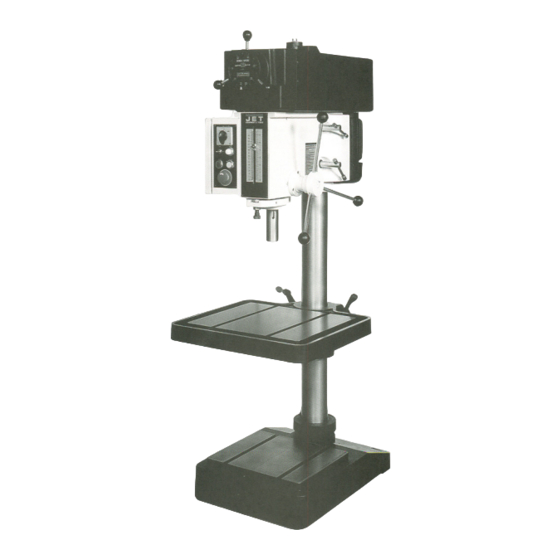
- Page 1 OPERATOR'S MANUAL JDP-20VS-1/3 Drill Press JET EQUIPMENT & TOOLS,INC. Walter A WMH Meier Holding Company .lET EQUIPMENT & TOOLS (JDP-20VS-3 shown) Po. BOX 1349 Auburn, WA 98071-1349 253-351-6000 Fax 253-939-8001 No. M-354201 1/98...
-
Page 2: Replacement Parts
Important Information 1-YEAR LIMITED WARRANTY REPLACEMENT PARTS Replacement parts for this tool are available directly form JET Equipment & Tools. To place an order, call 1-800-274-6848. Please have the following information ready: 1. Visa, MasterCard, or Discover Card number 2. Expiration date 3. - Page 3 For your own safety, read the operator's manual before operating the drill press. Do not wear gloves, neckties, long sleeves, jewelry, or loose clothing that may become caught in moving parts. Long hair must be contained. Clamp the workpiece or brace it against the column to prevent rotation.
- Page 4 REDUCE THE RISK OF UNINTENTIONALSTARTING. Make sure the switch is in the off position before plugging in. NEVER STAND ON A MACHINE. Serious injury could occur if the machine tipped or if the drill bit is unintentionally contacted. CHECK DAMAGED PARTS. Before further use of the machine, a guard or other part that is...
-
Page 5: Electrical Instructions
Caution: This tool must be grounded while in use to protect the operator from electric shock. Note: The JDP-20VS-1 is rated at 115/230V and comes pre-wired at 230V. The JDP-20VS-3 is rated at 230V and cannot be changed. In the event of a malfunction or breakdown, grounding provides a path of least resistance for electric current to reduce the risk of electric shock. - Page 6 Fig. C As received from the factory, the JDP-20VS-1 drill press is ready to run at 230 volt operation (the JDP- 20VS-3 is 230V and cannot be changed). This drill press, when the wiring is changed to 115 volt, is intended for use on a circuit that has an outlet and a plug that looks the one illustrated in Figure A.
- Page 7 The specifications in this manual are given as general information and are not binding. JET Equipment and Tools reserves the right to effect, at any time and without prior notice, changes or alterations to parts, fittings, and accessory equipment deemed necessary for any reason whatsoever. JDP-20VS-1 354201 1-1/2...
- Page 8 4. To prevent rust, apply a thin coat of paste wax to the table. Installation The drill press must be located in a dry, well lighted area with adequate room on all sides of the machine. The floor must be level and the drill press must rest solidly on the floor.
- Page 9 5. Tighten the two head locking bolts (A, Fig. 2). This will hold the head in place until the lock collar can be moved into position. The 2" x 4" can now be safely removed. 6. After the head is set at the desired height, loosen two set screws (8, Fig.
- Page 10 Turn to the left to select the high motor speed. Drill Tap Switch (8, Fig. 5) - the center position is the off position. Push the switch to the left for the drill function. Push the switch the right for the tap function.
- Page 11 Installing Drill Chuck Arbors or Taper Drill Bits 1: Disconnect the machine from the power source. 2. Make sure the spindle bore and the arbor or drill bit is clean. 3. Place a protective piece of scrap wood on the table.
- Page 12 Drill Speed Chart Use the following-drill speed charts to determine the approximate drill speed for the size bit and type of material to be drilled. Speeds are listed in revolutions per minute. 1/16 3/32 Drill Diameter (in.) Soft Wood 3000...
- Page 13 JDP-20VS-1/3 Head Assembly t(76 1" ",...
- Page 14 JDP-20VS-1/3 Head Assembly Index Part Description 70-1507 Push Rod Tube 70-1509 Push Rod 70-1508 Spindle Cover 70-1516 Carn Spring 70-1512 70-1515 Handle 70-1515-1 Ball A-632 Ball Bearing 71-1610 Speed Dial 70-1513 Bolt 70-1901 Motor (JDP-20VS-1 only) 70-1903 Motor (JDP-20VS-3 only)
- Page 15 JDP-20VS-1/3 Head Assembly (continued) 49 .. .JDP20VS-49 Screw... TS-0061041 Hex Cap BoiL TS-0680051 SpringWasher JDP20VS-52 Washer 3/16 x 3/8 7/16 x 1-1/4 7/16 ...3...
- Page 16 JDP-20VS-1/3 Variable Speed Assembly 13--@J 14.'/ 15~1 -~~y 36~. 18/~ $-26 $--28 32~.. ~>-37 ~./38 39~~~ -<'" ~--6 ",.'~ 1S:.4-- 29...
- Page 17 JDP-20VS-1/3 Variable Speed Assembly V-Belt 70-1206 70-1211 Upper MotorPulley 70-1023 MotorPulley Sleeve 70-1210 LowerMotorPulley 70-1024 Pulley Spring 70-1212 Spring Housing 70-1505 Hinge Pin 70-1502 Spindle ControlSupport 70-1504 Support Swivel BB-6302Z Ball Bearing 70-1501 Speed ControlFork 70-1506 Bearing Cup BB-6207Z BallBearing...
- Page 19 JDP-20VS-1/3 Column, Table, and Base Assembly 70-3008 Handle 70-1306 LiftCrank BB-51102 ... Thrust Bearing 70-1302 Worm Shaft 71-1301 Gear Box 70-1305 Worm Gear Shaft 71-1302 ... Gear 70-1303 Worm Gear 71-3003 Gear Rack.. 71-3005 Column 70-1008 Collar 12., 71-2001 Table...
- Page 20 JDP-20VS-1/3 Depth Stop and Control Box Assembly...
- Page 21 HexSocketCap Screw JDP20VS-27 Screw JDP20VS-28A TS-0270111 Set Screw TS-0561021 HexNuL TS-0267021 .. Set Screw 32..JDP-20VS-32....Round Head TS-0680011 Washer .JDP-20VS-34 Limite Plate 3 x 20 5/8-18UNF 5/16 x 1-1/4 5/16x 1-1/4 3/16x 1/2...
-
Page 22: Electrical Panel Components
Electrical Panel Components (JDP- 0 V. Transformer 24V. S S T 1 T1 -L 0, 220V 380V. CL-4L [£] 440V 1, 7, 8, 9 , 10, 12, 13, Switch Drill 9l8Ti2 @] Light G:1' 12 7l6T7 20VS-3) C-11 L [ill... - Page 23 Electrical Panel Components (JDP-20VS-3 only) E-101 High-Low Switch E-102 Start Button E-103 ""'"'''''''''''''''' Drill-Tap Switch E-104 ReturnSwitch E-106 Emergency Stop Switch E-013 Fuse(2AMP) E-014 Fuse Seat E-111 Transformer E-016 Magnetic Starter (CL-4L) E-015 Magnetic Starter (C-11L) E-110 Terminal Relay 12 """"...
- Page 24 2 V2 U2 W 1 V1 U1 TC220V AC24V Stop r--- Drill LS 1 0--2.2...0 I , c::b Start .. 0 Return : Lo- t:::J...