Jet JDP-15M Operating Instructions And Parts Manual
Jet jdp-15m drill press: user guide
Hide thumbs
Also See for JDP-15M:
- Operating instructions and parts manual (24 pages) ,
- Operating instructions manual (80 pages) ,
- Operating instructions manual (20 pages)

Related Manuals for Jet JDP-15M


Summary of Contents for Jet JDP-15M
-
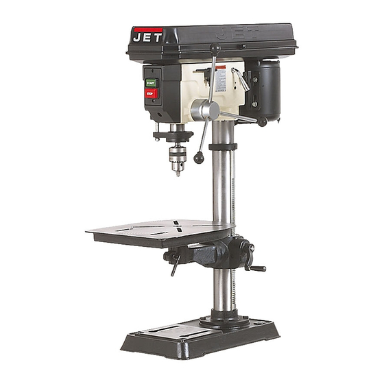
Page 1: Drill Press
Operating Instructions and Parts Manual Drill Press Model: JDP-15M/MF WMH TOOL GROUP 2420 Vantage Drive Elgin, Illinois 60123 Part No. M-354165 Ph.: 800-274-6848 Revision A 11/03 www.wmhtoolgroup.com Copyright © WMH Tool Group... -
Page 2: Warranty
This manual has been prepared for the owner and operators of a JDP-15M/MF Drill Press. Its purpose, aside from machine operation, is to promote safety through the use of accepted correct operating and maintenance procedures. Completely read the safety and maintenance instructions before operating or servicing the machine. -
Page 3: Table Of Contents
230 Volt Operation... 13 Grounding Instructions ... 14 Extension Cords ... 14 Troubleshooting ... 15 Exploded View Drawing JDP-15M/MF... 17 Parts List JDP-15M/MF ... 18 Wiring Diagram ... 21 JDP – 15M/MF – 115V ... 21 JDP – 15M/MF – 230V ... 21 The specifications in this manual are given as general information and are not binding. -
Page 4: Warnings
4. This drill press is designed and intended for use by properly trained and experienced personnel only. If you are not familiar with the proper and safe operation of a drill press, do not use until proper training and knowledge have been obtained. - Page 5 20. Keep visitors a safe distance from the work area. Keep children away. 21. Make your workshop child proof with padlocks, master switches or by removing starter keys. 22. Give your work undivided attention. Looking around, carrying on a conversation and “horse-play” are careless acts that can result in serious injury.
-
Page 6: Specifications
Net Weight ... 156 lbs..161 lbs. Gross Weight ... 163 lbs..167 lbs. Carton Size (L x W x H/in):... 32 x 22 x 12 ... 56 x 20 x 11 JDP-15M 3/4HP, 115/230V, 60Hz, 1Ph JDP-15MF... -
Page 7: Shipping Contents
Shipping Contents Unpack the carton and verify that all parts listed below are included. Main Parts 1 ea Head Assembly 1 ea Table 1 set Column and Table Bracket Assembly 1 ea Base Additional Parts 1 set Chuck and Chuck Key 1 pc Arbor 1 pc... -
Page 8: Assembly
1. Remove the contents from the shipping container. 2. Compare the contents of the shipping container with the list found above. Report any shortages or damage to your JET distributor. 3. Clean all rust protected surfaces with kerosene or a light solvent. -
Page 9: Column Lock Handle
Figure 4 Column Lock Handle Referring to Figure 5: Thread the column lock handle (D) into the table bracket (E). Figure 5 Table Installation Referring to Figure 6: 1. Place the table (A) on the bracket (B). 2. Tighten the table lock handle (C). Figure 6 Head Assembly Referring to Figure 7:... -
Page 10: Chuck And Arbor Removal
Figure 8 Chuck and Arbor Removal Referring to Figure 9: 1. Unplug machine from the power source. 2. Raise the table until it is about seven inches below the chuck. 3. Place a piece of scrap wood on the table, and lower quill (A) using the downfeed handle. -
Page 11: Return Spring Adjustment
6. Tighten two bar knobs (E, Fig. 11). Belts are properly tensioned when finger and thumb pressure midway between the two pulleys causes approximately ½” deflection. Figure 11 Return Spring Adjustment The return spring is adjusted at the factory and should need further... -
Page 12: Work Light
Using the Vise For the small workpiece that cannot be clamped to the table, use a drill press vise. The vise must be clamped or bolted to the table. Always use a back-up piece of scrap wood to cover the table. -
Page 13: Maintenance
UL/CSA listed plug suitable for 230V operation (D). Contact your local Authorized JET Service Center or qualified electrician for proper procedures to install the plug. The drill press must comply with all local and national codes after the 230-volt plug is installed. -
Page 14: Grounding Instructions
Remember, the smaller the gauge number, the heavier the cord. equipment- equipment- The drill press with a 230-volt plug should only be connected to an outlet having the same configuration (D, Fig. 17). No adapter is available or should be used with the 230-volt plug. -
Page 15: Troubleshooting
Troubleshooting Trouble Probable Cause Drill press unplugged from wall, or motor. Drill press will not Fuse blown, or circuit breaker tripped. start. Cord damaged. Starting capacitor bad. Extension cord too light or too long. Drill press does not come up to speed. - Page 16 Troubleshooting (cont.) Trouble Probable Cause Bent drill bit. Excessive drill bit Worn spindle bearings. runout, or wobble. Bit, or chuck not properly installed. Quill returns too slow, Spring has improper tension. or too fast. Chuck or arbor does Dirt, grease, etc on arbor, chuck, or not stay in place.
-
Page 17: Exploded View Drawing Jdp-15M/Mf
Exploded View Drawing JDP-15M/MF... -
Page 18: Parts List Jdp-15M/Mf
2B ...10600204 ...Column Holder for JDP-15MF..1 3 ...TS-2279121 ...Hex Socket Set Screw ... M10-12... 3 4A ...JDP15-1004A...Body Column for JDP-15M ..1 4B ...JDP15-1004B...Body Column for JDP-15MF ..1 5 ...TS-2229403 ...Hex Head Bolt ... M10x40 ... 4 6 ...10600604 ...Table Bracket ... - Page 19 Parts List JDP-15M/MF Index No. Part No. 59 ...2001ZZ6204...Ball Bearing..1 61 ...2001ZZ6203...Ball Bearing..1 62 ...TS-2360161 ...Washer... M16 ... 1 63 ...10606301 ...Nut Lock ..1 64 ...10606401 ...Spindle Nut..1 65 ...10606505 ...Driving Sleeve ..1 ...JDP15-1065 ...Driving Sleeve Assy (includes #65 thru #67) ...
- Page 20 Parts List JDP-15M/MF Index No. Part No. Description Size 166 ...JDP15-1166 ...Speed Diagram ..1 169 ...JDP15-1169 ...Trade-Mark Label..1 170 ...2658MZDU36...Drive Screw... Φ 2.3-5... 6 601 ...TS-2245082 ...Cr. Re. Pan Head Screw... M5-8... 4 602 ...TS-0733031 ...External Tooth Lock Washer... No 10 ... 2 610 ...TS-1534692 ...Cr.
-
Page 21: Wiring Diagram
Wiring Diagram JDP – 15M/MF – 115V JDP – 15M/MF – 230V... - Page 22 NOTES...
- Page 23 NOTES...
- Page 24 WMH Tool Group 2420 Vantage Drive Elgin, Illinois 60123 Phone: 800-274-6848 www.wmhtoolgroup.com...