Table of Contents
Advertisement
Advertisement
Table of Contents

Related Manuals for Jet JDP-17FSE


Summary of Contents for Jet JDP-17FSE
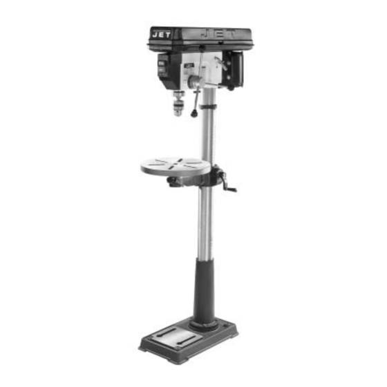
- Page 1 OWNER'S MANUAL JDP-17FSE JET Drill Press WMH TOOL GROUP Consumer/Light Industrial Products Division P.O. BOX 1349 Auburn, WA 98071-1349 Ph: 1-800-274-6848 Fax: 1-800-274-6840 E-mail: jet@wmhtoolgroup.com www.wmhtoolgroup.com M-354171 11/02 Copyright © WMH Tool Group...
-
Page 2: Warranty
This manual has been prepared for the owner and operators of a JDP-17FSE Drill Press. Its purpose, aside from machine operation, is to promote safety through the use of accepted correct operating and maintenance procedures. Completely read the safety and maintenance instructions before operating or servicing the machine. -
Page 3: Warnings
This drill press is designed and intended for use by properly trained and experienced personnel only. If you are not familiar with the proper and safe operation of a drill press, do not use until proper training and knowledge has been obtained. - Page 4 DO NOT operate tool while under the influence of drugs, alcohol or any medication. DO NOT drill pieces of material that are too small to be safely supported. WHEN drilling a large workpiece, provide additional support at table height.
-
Page 5: Grounding Instructions
115 Volt Operation As received from the factory, your drill press is ready to run at 115 volt operation. This drill press, when wired for 115 volt, is intended for use on a circuit that has an outlet and a plug that looks like the one illustrated in (A). -
Page 6: 230V Operation
230 volt plug is installed. 4. The drill press with a 230 volt plug should only be connected to an outlet having the same configuration (D). No adapter is available or should be used with the 230 volt plug. -
Page 7: On-Off Switch Padlock
On-Off Switch Padlock Model No. BP-1, Stock No. 709736 To safeguard your machine from unauthorized operation and to avoid accidental starting by young children, the use of a padlock is highly recommended. JET model BP-1 is available from your local authorized JET distributor or by calling JET Equipment &... -
Page 8: Table Of Contents
Specifications: JDP-17FSE Stock Number... 354171 Swing ...16-1/2” Type ...Floor Drilling Capacity ...5/8” Chuck Size ...5/8” Spindle Travel ...3-3/8” Spindle Distance to Base...49” Spindle Distance to Table (max.)...29-1/8” Table Size Diameter ...13-3/4” Spindle Taper ...MT-2 Column Diameter ...3-1/8” Number of Spindle Speeds ... 12 Range of Spindle Speeds ... -
Page 9: Contents Of Shipping Container
Contents of the Shipping Container 1. Head Assembly 1. Table 1. Column and Bracket Assembly 1. Base 1. Owner’s Manual 1. Warranty Registration Card 1. Chuck and Chuck Key 3. Downfeed Handle 1. Table Bracket Lock Handle 1. Table Bracket Raising Handle 4. -
Page 10: Assembly
Assembly 1. Place the base (A, Fig. 1) on a level floor. 2. With a 17mm wrench attach the column assembly (B, Fig. 1) to the base (A, Fig. 1) with four M10 x 40 hex cap bolts (C, Fig. 1). Tighten firmly. -
Page 11: Removing The Chuck And Arbor
9. With the aid of a second person, carefully lift the head onto the column top. Caution: The head assembly is heavy! Use care when lifting onto the column! 10. Rotate head assembly until sides of the belt cover are parallel with the sides of the base. 11. -
Page 12: Adjusting The Depth Stop
3. Tighten lock knob. 4. The drill bit will now advance to this depth. Changing Spindle Speeds A spindle speed and belt arrangement chart are found on the inside of the belt cover, see Figure Refer to this chart whenever changing speeds. -
Page 13: Speed And Pulley Chart
Speed & Pulley Chart... -
Page 14: Return Spring Adjustment
Return Spring Adjustment The return spring is adjusted at the factory and should not need further adjustment. adjustment is deemed necessary: 1. Unplug the machine from the power source. 2. Loosen two jam nuts (A, Fig. 10). Do not remove. 3. -
Page 15: Basic Operation
Feeding too slowly may cause burning of the workpiece. Feeding too quickly may cause the motor to stop and/or the drill bit to break. Generally speaking, the smaller the drill bit, the greater the RPM required. -
Page 16: Troubleshooting
Trouble Drill press will not start. Drill press does not come up to speed. Drill Press vibrates excessively. Noisy Operation. Workpiece Burns. Drill bit wanders. Wood splinters on the underside. Drill bit binds in workpiece. Excessive drill bit runout, or wobble. -
Page 17: Part's Breakdown
Parts Breakdown for JDP-17FSE... -
Page 18: Part's List
Parts List for JET JDP-17FSE Drill Press Index Part Description Size 1...10800101 ... Base ..1 2...12909001A1... Column Holder Assy (incl. #2,3,4)..1 3...TS-1525021 ... Socket Set Screw ... M10x12 ... 1 4...12909001 ... Body Column..1 5...TS-1491061 ... - Page 19 Index Part Description 57 ...10705703 ... Rubber Washer ..1 58 ...10705825 ... Spindle ..1 59 ...BB-6205Z... Ball Bearing..1 61 ...BB-6203ZZ ... Ball Bearing..1 62 ...10606201 ... Washer..1 63 ...10606301 ... Lock Nut ..1 64 ...10606401 ...