Table of Contents
Advertisement
Quick Links
Advertisement
Chapters
Table of Contents

Related Manuals for Denso BHT-100B


Summary of Contents for Denso BHT-100B
- Page 1 User's Manual...
- Page 2 Copyright © DENSO, 2001 All rights reserved. No part of this publication may be reproduced in any form or by any means without permission in writing from the publisher. Specifications are subject to change without prior notice. All products and company names mentioned in this manual are trademarks or regis-...
- Page 3 Preface Please READ through these operating instructions carefully. It will enable you to operate your BHT-100Q/100B correctly. After you have finished reading the instructions, keep this manual handy for speedy reference.
- Page 4 How this book is organized This manual is made up of five chapters and appendices. Chapter 1. Quick Guide Describes the basic operating method of the BHT and the related notes. Chapter 2. Getting Started the BHT and System Mode Summarizes the BHT system configuration and describes the operation including preparation and System Mode (which is required for the efficient use of application programs).
-
Page 5: Related Publications
■ Technical Terms Used in This Manual Source Program and Object Program (User Program) Generally, a source program is translated into an object program by a compiler. This manual calls an object program a user program. BHT-BASIC This manual expresses BHT-BASIC3.0 and BHT-BASIC3.5 as BHT-BASIC. ■... -
Page 6: Safety Precautions
SAFETY PRECAUTIONS Be sure to observe all these safety precautions. ■ Please READ through this manual carefully. It will enable you to use the BHT and CU correctly. ■ Always keep this manual nearby for speedy reference. Strict observance of these warning and caution indications are a MUST for preventing accidents which could result in bodily injury and substantial property damage. - Page 7 Handling the BHT • The BHT-100B uses a laser light for indicating the scanning range. The intensity of the laser light might be too low to inflict bodily injury. However, do not look into the laser beam.
- Page 8 • Do not look into the light source through the reading window or point the light source towards the eyes. The light emitted through the reading window is harmful to the eyes. • Do not poke at the eyes with the stylus that comes with the BHT. Handling the CU •...
- Page 9 Basic handling tips • Never put the BHT in places where there are excessively high temperatures, such as inside closed-up automobiles, or in places exposed to direct sunlight. Doing so could affect the housing or parts, resulting in a fire. •...
- Page 10 • If you drop the BHT so as to damage its hous- ing, immediately turn off the power, pull out the rechargeable battery cartridge or dry bat- tery cartridge, and contact your nearest dealer. Failure to do so could cause smoke or fire. •...
- Page 11 DENSO WAVE INCORPORATED ("DENSO WAVE") takes reasonable precautions to ensure its products do not infringe upon any patent of other intellectual property rights of other(s), but DENSO WAVE cannot be responsible for any patent or other intellectual property right infringement(s) or violation(s) which arise from (i) the...
- Page 12 ■ Proper Care of the BHT and CU Clean the housings, battery cartridge terminals, and CU-7001 charge terminals with a dry, soft cloth. Before cleaning, be sure to turn the BHT power off and unplug the AC adapter of the CU. •...
-
Page 13: Fcc Regulations
FCC WARNING: Changes or modifications not expressly approved by the party re- sponsible for compliance could void the user’s authority to operate the equipment. FCC Regulations Labeling *Only for the BHT-100B. - Page 14 Chapter 1 Quick Guide ... 1 Reading 2D Codes and Bar Codes ... 2 BHT-100Q ... 2 BHT-100B ... 4 Setting and Using the Hand Strap and Stylus ... 6 Setting the Backlight ... 8 Using the Keypad ... 9 Transferring Data ...
- Page 15 RS-232C Interface Specifications ... 146 Appendices ... 148 Appendix A. Specifications ... 149 BHT-100Q ... 149 BHT-100B ... 156 CU-7000 ... 161 Appendix B. Communications Protocol Details ... 163 BHT-protocol ... 163 BHT-Ir protocol ... 173 Appendix C. A Typical Basic Operation ... 184 Appendix D.
- Page 16 Chapter 1. Quick Guide Chapter 2. Getting Started the BHT and System Mode Chapter 3. Communications Operations of the BHT Chapter 4. Error Messages Chapter 5. Handling the CU-7000 (Option) Appendices...
-
Page 17: Table Of Contents
This chapter describes the basic operating method of the BHT and the related notes. Reading 2D Codes and Bar Codes ... 2 BHT-100Q ... 2 BHT-100B ... 4 Setting and Using the Hand Strap and Stylus ... 6 Setting the Backlight ... 8 Using the Keypad ... -
Page 18: Reading 2D Codes And Bar Codes
• The markers show the left-to-right scanning range. When the scanning distance is 8.5 to 9.5 cm (3.3 to 3.7 inches), they indicate almost the center of the up-down scanner’s view. If the distance is out of the range, those markers will deviate from the center. - Page 19 • Before reading 2D codes or bar codes, clean those labels if stained. • Avoid using the BHT in direct sunlight. The BHT might fail to read correctly. • To read 2D codes or bar codes on curved surfaces, apply the BHT to the target code so that the code comes to the center of the scanning range indicated by the markers.
-
Page 20: Bht-100B
Turn the BHT power on, bring the bar-code reading window to the bar code to be scanned, and press the trigger switch. The BHT-100B emits a laser light to indicate the scanning range and turns on the illumination LED to scan the bar code. - Page 21 • Before reading bar codes, clean those labels if stained. • Avoid using the BHT in direct sunlight. The BHT might fail to read correctly. • To read bar codes on curved surfaces, apply the BHT to the target bar code so that the code comes to the center of the scanning range indicated by the laser beam.
-
Page 22: Setting And Using The Hand Strap And Stylus
1.2 Setting and Using the Hand Strap and Stylus ■ Setting the hand strap Hand strap ■ Using the hand strap Put your hand through the hand strap and hold the BHT as shown below. This will prevent you from dropping the BHT accidentally. Hand strap... -
Page 23: Using The Stylus
■ Setting the stylus ■ Using the stylus The BHT has a touch screen LCD that enables you to use touch keys and draw images on the touch screen with the stylus if you have defined those touch keys and graphics pad box in user programs, respectively. -
Page 24: Setting The Backlight
1.3 Setting the Backlight Pressing the right-hand trigger switch (M4 key) while holding down the SF (Shift) key activates or deactivates the backlight function. In user programs, you can select the key to be used for activating or deactivating the backlight function (instead of the initial setting: combination of SF and the right-hand trigger switch), as well as modifying the ON-duration of the backlight before the automatic turning-off. -
Page 25: Using The Keypad
Chapter 1. Quick Guide 1.4 Using the Keypad ■ Entering Numerical Data To enter numerical data, e.g., the quantity of goods, use the ten numerical keys and the ENT key. For example, to enter the number "120," press the 1, 2 and 0 keys and then press the ENT key. -
Page 26: Transferring Data
1.5 Transferring Data ■ Using infrared link Using infrared rays, the BHT may transfer data directly to the host computer equipped with an IrDA interface port and other IrDA-compliant devices. • Make sure that there is no obstruction in the light path between the BHT and any target stations. -
Page 27: Chapter 2 Getting Started The Bht And System Mode
This chapter summarizes the BHT system configuration and describes the operation including preparation and System Mode (which is required for the efficient use of application programs). BHT System Configuration ... 12 Components and Functions ... 17 Preparation ... 19 2.3.1 Setting-up 1: Loading the Battery Cartridge ... 19 2.3.2 Setting-up 2: Setting the Calendar Clock ... -
Page 28: Bht System Configuration
2.1 BHT System Configuration The BHT barcode data collection system requires the following hardware as well as the BHT Bar Code Handy Terminal (which reads 2D codes or bar codes and accepts key entry) as illustrated below: Host computer: For host computers having no IrDA interface ports, the optional CU-7000 optical communications unit and RS-232C interface cable are available. -
Page 29: Host Computer
Host Computer Models: PC/AT, PS/2 Optional application programs and OSes MS-DOS Applications BHT-BASIC3.0 BHT-BASIC Compiler (MS-DOS–based) MS-DOS– Ir-Transfer Utility C based — Ir-Transfer Utility E MS-DOS– Transfer Utility based *This application does not activate any built-in port. CU-7000 and RS-232C Interface Cable (option) The CU-7000 is an IrDA-compliant communications unit which is required when your host computer is not equipped with an IrDA interface port. - Page 30 Ir-Transfer Utility C (option) Running on the host computer, this utility transfers files between the BHT and the host computer. For its file transfer control procedure, the utility uses the BHT-Ir protocol. (For the details about the BHT-Ir protocol, refer to Chapter 3, Subsection 3.4.2.) To transfer files under any of the following conditions, use Ir-Transfer Utility C: At transmission speeds of 115200 or 57600 bps (This may be impossible de- pending upon the host computer type.)
- Page 31 Software Structure System Programs and JIS Level 1 & Level 2 fonts are resident in the system area and user area, respectively. To use extension programs and user programs, you should download the program files into the user area. To use data files (e.g., goods master files) required for execution of user programs, you should download those data files before execution of user programs.
- Page 32 System Mode System Mode is a system program exclusively designed for the effective use of user programs in the BHT. It sets up the execution environments for those programs; e.g., it prepares downloading/uploading conditions, sets the calendar clock, and tests the BHT components including the LCD, beeper, and keypad.
-
Page 33: Components And Functions
2.2 Components and Functions Indicator LED Illuminates in green when the BHT has successfully read a code. Trigger switch (M3 key) Press this switch to start code reading. Optical interface port Used to exchange data/programs with the host computer via its integrated IR port or via the optical communication unit CU-7000. - Page 34 The functions of the keys may be set by user programs. Shown below is a set of sample functions. Numerical keys Used for numerical input. BS (Backspace) key Moves back one character. C (Clear) key Clears the last inputted data or returns to the original screen.
-
Page 35: Preparation
2.3 Preparation 2.3.1 Setting-up 1: Loading the Battery Cartridge Before the first use of the BHT, be sure to load the battery cartridge as shown below. The battery cartridge is not loaded in the BHT when shipped from the factory. Charge the rechargeable battery cartridge. - Page 36 • Never charge the dry battery cartridge. • The BHT has an integrated backup power source which backs up the memory and calendar clock in the BHT when no battery cartridge is loaded or the voltage level of the battery cartridge drops below the specified level. The backup power source is automatically charged by the battery cartridge.
-
Page 37: Low Battery Indication
Chapter 2. Getting Started the BHT and System Mode Low Battery Indication Low battery indication—Level 1 If the battery output voltage drops below a specified lower level limit while the BHT is in operation, the BHT displays the following Level 1 message for approx. 2 seconds and beeps three times. - Page 38 • When replacing dry cells, always replace both of them with new alkaline manga- nese batteries (LR6). • You may charge the rechargeable battery cartridge with the optional CU-7001 communication unit or optional C-700/C-750 charger. For the charging proce- dure using the CU-7001, refer to Chapter 5. For that using the C-700/C-750, refer to the "C-700 User's Manual"/"C-750 User's Manual."...
-
Page 39: Setting-Up 2: Setting The Calendar Clock
2.3.2 Setting-up 2: Setting the Calendar Clock Turn the BHT on by pressing the PW key. The following message will appear. In the following cases, the above message will appear. In such instances, it is necessary to set the date and time. (The indication "00/01/01 00:00" will differ depending upon the calendar clock state.) •... -
Page 40: Adjusting The Lcd Contrast, Beeper Volume And Touch Screen, And Switching The Beeper & Vibrator
2.3.3 Adjusting the LCD Contrast, Beeper Volume and Touch Screen, and Switching the Beeper & Vibrator While holding down the M1 key or right-hand trigger switch (M4), press the PW key. The main adjustment screen appears which differs depending upon the current state as shown below. -
Page 41: Adjusting The Lcd Contrast
Adjusting the LCD contrast You can adjust the LCD brightness to eight contrast levels. (1) Use the 1 key (or M1 or M2 key) to select the LCD CONTRAST line. (2) To decrease the contrast, press the M1 key with the SF key held down; to increase it, press the M2 key with the SF key held down. - Page 42 Adjusting the touch screen At the first use of the touch screen or if the touch areas seem to deviate from the nor- mal positions when in use, adjust the touch screen according to the steps given below. ⇓ ⇓ Use the 5 key (or M1 or M2 key) to select the CALI- BRATION line, then press the ENT key.
- Page 43 Chapter 2. Getting Started the BHT and System Mode Touch the center of the 4th "+." The adjustment will complete and the display will return to the main adjustment screen. If the adjustment is not completed normally, the screen shown at left will appear where you may choose retry or not.
-
Page 44: Battery Voltage Display
2.3.4 Battery Voltage Display The battery voltage level is always displayed on the status indicator line (bottom line). Status Indicators The displayed battery level shows the terminal voltage of the battery, not how much power is left. The battery voltage level varies depending upon the operation of the BHT, so the displayed level also may vary. -
Page 45: Battery Replacement Notes
2.3.5 Battery Replacement Notes When is battery replacement needed? If the "Charge the battery!" or "Replace the batteries!" appears on the LCD, replace the rechargeable battery cartridge with a fully charged one or replace the dry cells with new ones, respectively. If you leave the BHT without replacing the rechargeable battery cartridge or dry cells, the integrated calendar clock or data will no longer be backed up so that the calendar clock will stop or the message "Contact your administrator. - Page 46 If the run time is noticeably shorter than normal, replace the battery cartridge with a new one. • Use only DENSO WAVE-authorized battery cartridges and chargers. • Never dispose of batteries into a fire. • When disposing of battery cartridges, cover their terminal pins with vinyl tape to prevent short-circuit.
-
Page 47: Bht Turning-Off Notes
Chapter 2. Getting Started the BHT and System Mode 2.3.6 BHT Turning-off Notes [ 1 ] "Shutdown in progress" message When the BHT is turned off by pressing the PW key or by the auto power-off feature, it displays the following message and starts preparation for shutdown. When the above message is displayed, do not remove the battery cartridge. - Page 48 Press the 2 key while holding down the SF key. The screen will switch to the following: [ 1 ] YES: Run Scandisk and start the System. [ 2 ] NO: Turn the BHT off. Choose either one with the numerical keys and press the ENT key. When Scandisk is in progress, the following message is displayed:...
- Page 49 If Scandisk finds an invalid file(s), the following screen will appear. As long as an invalid file exits, that screen displays every time the BHT System is started up. Press the ENT key to start up the BHT System. Scandisk when the resume function is enabled If Scandisk runs when the resume function is enabled, the screen given below may appear.
-
Page 50: 3 ] About "$$Brklst.sys
[ 3 ] About "$$BRKLST.SYS" If Scandisk finds an invalid file(s), it will automatically create the "$$BRKLST.SYS" file. To check the contents of the file, upload the file in System Mode to the host computer. (Refer to Subsection 2.5.3, "[ 3 ] Uploading.") Contents of the "$$BRKLST.SYS"... -
Page 51: Initializing The Bht System
2.4 Initializing the BHT System Initializing the system will lose program files and data files stored in the user area and the system settings will revert to the factory defaults. You may delete font files by selecting the whole user area to be initialized. You need to initialize the system when: you want to delete all of the program files and data files. - Page 52 Selecting the memory area to be initialized (Area selection screen) Selecting the English or Japanese message version Press the PW key while holding down the SF, M1 and 0 keys together. The screen shown at left will appear. To initialize the user area except for the font file area, press the ENT key.
- Page 53 Confirming the memory area selected for initialization During initialization Progress in initialization Chapter 2. Getting Started the BHT and System Mode Selecting the "USER AREA EXCEPT FONTS" in step (1) above will call up the confirmation screen shown at left. 1 Yes : Starts initialization.
- Page 54 Completion of initialization • Do not turn the BHT off until the above initialization completion screen appears. A too-early powering-off will interrupt initialization, requiring you to initialize the BHT again. • If the message "Contact your administrator. Note the error number. (2XXX)" appears although the initialization has completed, initialize the BHT again.
-
Page 55: Operating In System Mode
2.5 Operating in System Mode System Mode is an operating software exclusively designed for the effective use of the BHT, which includes various functions as shown on the following pages. 2.5.1 Starting System Mode To start up System Mode, turn the BHT power on while holding down the SF and 1 keys. - Page 56 FUNC keys, and resume function. Shown at left is the BHT-100Q screen. The BHT-100B screen displays "4:BARCODE" instead of "4:QRCODE." (Refer to Subsection 2.5.3, [ 4 ].)
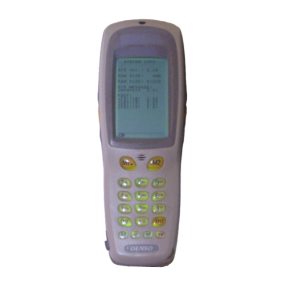
- Page 57 LED test, touch screen test, key-entry test, vibrator test, and file test. Shown at left is the BHT-100Q screen. The BHT-100B screen displays "1:BARCODE" instead of "1:QRCODE." (Refer to Subsection 2.5.3, [ 5 ].) System Information Shows the system program version, memory size, system message version, and JIS font type and version.
- Page 58 In addition to the functions given on the previous pages, System Mode has these four functions: Deleting files, Downloading/uploading the BHT system parameter file, Set- ting the remote wakeup parameters, and Downloading/uploading the system message file. To call up these functions, press the 0, 3, 4 or 6 key, respectively, while holding down the SF key when the SYSTEM MENU is displayed.
-
Page 59: Operating In System Mode
M1 and M2 keys to select "3:COM PORT." Chapter 2. Getting Started the BHT and System Mode ENT key C key ENT key C key ENT key C key BHT-100B ENT key C key ENT key C key ENT key C key... -
Page 60: 2 ] Selecting A Desired Setting
[ 2 ] Selecting a desired setting First, select a desired item on the current screen by using the numerical key or the M1 and M2 keys so as to highlight the desired item. Next, while holding down the SF key, use the M1 and M2 keys to select a desired setting and then press the ENT key. -
Page 61: Detailed Description Of The Functions In System Mode
2.5.3 Detailed Description of the Functions in System Mode [ 1 ] Program Execution ⇓ Chapter 2. Getting Started the BHT and System Mode Selecting "1:EXEC PROGRAM" on the SYSTEM MENU calls up the screen shown at left. If more than one program has been downloaded to the user area of the target memory, use the M1 and M2 keys to move the cursor to a target program, and then press the ENT key. - Page 62 ⇓ In the example shown at left, 26 programs are downloaded. If no program file is downloaded, the message shown at left will appear. To return to the SYSTEM MENU, press the C key.
-
Page 63: 2 ] Downloading
[ 2 ] Downloading If you download a file having the same name as one already used in the user area of the target memory in the BHT, the newly downloaded file replaces the old one. Carrying out "2:HT<-->HT COPY" will not copy the JIS1 and JIS2 font files. Those font files may be downloaded by "1:FILE."... - Page 64 Download screens With this screen displayed, the BHT waits for a file to be downloaded. If you select "2:HT<-->HT" on the DOWNLOAD menu, the "HT<-->HT" will appear in the center of the 2nd line. If you select "1:FILE," nothing will ap- pear on the 2nd line.
- Page 65 If an error occurs during downloading If some error occurs during downloading, the BHT beeps three times and shows one of the following screens with the prompt "Retry?": To retry the download, press the 1 and ENT keys; to abort it, press the 2 and ENT keys. Chapter 2.
- Page 66 Problem The current download will exceed the maximum of 80 files in the memory. Solution Press the 2 key to return to the SYSTEM MENU. Delete unnecessary files in memory or decrease the number of files to be downloaded if you at- tempted to download more than one file.
-
Page 67: 3 ] Uploading
[ 3 ] Uploading Carrying out "3:HT<-->HT COPY" will not copy the JIS1 and JIS2 font files. Those font files may be uploaded by "1:ONE FILE" or "2:ALL FILES." Chapter 2. Getting Started the BHT and System Mode Selecting "3: UPLOAD" on the SYSTEM MENU calls up the screen shown at left. - Page 68 If you select "1:ONE FILE" or "2:ALL FILES" on the UPLOAD menu when no files are stored in the memory, the message shown at left will appear. Pressing the C key returns to the UPLOAD menu. Upload screens If you select "1:ONE FILE" and choose a file to be uploaded or if you select the "2:ALL FILES"...
- Page 69 If an error occurs during uploading If some error occurs during uploading, one of the following screens will appear and the beeper beeps three times. To retry the uploading operation, press the 1 and ENT keys; to abort it, press the 2 and ENT keys.
-
Page 70: 4 ] System Environment Setting
[ 4 ] System Environment Setting BHT-100Q BHT-100B Selecting "4: SET SYSTEM" on the SYSTEM MENU calls up the screen shown at left. 1 EXEC PROGRAM : Sets an execution program to be run when the power is turned on. - Page 71 Chapter 2. Getting Started the BHT and System Mode [4.1] Setting an execution program Selecting "1: EXEC PROGRAM" on the SET SYS- TEM menu calls up the screen shown at left. Highlighted is the current setting. Use the M1 and M2 keys to move the cursor to a desired execution program to be run when the power is applied, and then press the ENT key.
- Page 72 [4.2] Setting the message version Selecting "2: DISPLAY" on the SET SYSTEM menu calls up the screen shown at left. Highlighted is the current setting. 1 MESSAGE: Switches the message version to English or Japanese for system error messages and indications on the screen for the LCD con- trast, beeper volume and touch screen adjustment and the beeper...
- Page 73 [4.3] Setting the calendar clock ⇓ ⇓ Chapter 2. Getting Started the BHT and System Mode Selecting "3:DATE/TIME" on the SET SYSTEM menu calls up the screen shown at left. Use the numerical keys to enter the year (only the last two digits), month, day, hour, and minute in this order, and then press the ENT key.
- Page 74 [4.4] Setting the special scanning parameters BHT-100Q Black-and-white inverted label reading function (INVERT) This function makes it possible to read white bars on a black background. When this function is activated, the BHT-100Q cannot read codes other than QR codes. Selecting "4: QRCODE"...
- Page 75 View Finder If the View Finder is set to ON, the LCD shows the scanned image of a code lying inside the scanner's view when you scan the code. Upon completion of scanning, the view finder display goes off. Setting the View Finder to ON decreases the scanning speed.
- Page 76 • PDF417 Data read Example: If a code read is "PDF417, Error correction level 4, 12 rows and 2 digits," then the option data below will follow. (Data read)… Y1041202 • MaxiCode Data read Example: If a code read is "MaxiCode and Mode 4," then the option data below will follow.
- Page 77 BHT-100B Black-and-white inverted label reading function (INVERT) This function makes it possible to read white bars on a black background. Activating this function might increase the frequency of bar-code reading errors. This function can usually be set to OFF. DECODE LEVEL You may set the decode level.
- Page 78 Marker You may select the marker ON/OFF mode from the following: 0: Driven by the trigger switch 1: Fixed to ON 2: Fixed to OFF If you select "1" (Fixed to ON), the markers will keep ON so that power consump- tion is higher than that in other modes and the battery working time becomes short.
- Page 79 [4.5] Setting the communications environments After the BHT is initialized, the interface port and communications parameters are set as listed in the default table below. Do not access them unless necessary. Interface port Communications protocol Communications parameters for the optical interface port TRANSMIT SPEED PROTOCOL (Protocol options)
- Page 80 [4.5-1] Setting the communications parameters for the optical interface Selecting the "5: COM" on the SET SYSTEM menu calls up the screen shown at left. 1 OPTICAL: Switches to the communi- cations parameters setting screen for the optical inter- face . 2 CONNECTOR: Switches to the communi- cations parameters setting...
- Page 81 Communications parameters setting screen Communications protocol option screen Chapter 2. Getting Started the BHT and System Mode Selecting "1:PARAMETER" on the SET OPTICAL screen calls up the screen shown at left. Highlighted is the current setting. Select the desired transmission speed by using the numerical keys or SF+M1 and SF+M2 keys, and then press the ENT key.
- Page 82 [4.5-2] Setting the communications parameters for the direct-connect interface (1) Communications parameters setting screen Selecting "2:CONNECTOR" on the SET COM menu calls up the screen shown at left. 1 PARAMETER: Switches to the commu- nications parameters set- ting screen. 2 PROTOCOL: Switches to the commu- nications protocol option screen.
- Page 83 Communications protocol option screen Chapter 2. Getting Started the BHT and System Mode Selecting "2:PROTOCOL" on the SET CONNECTOR screen calls up the screen shown at left. Highlighted is the current setting. 1 SERIAL No.: Selects whether or not the system will add serial num- bers to data blocks.
- Page 84 [4.5-3] Setting the interface port Selecting the "3:COM PORT" on the SET COM menu calls up the screen shown at left. Highlighted is the current setting. 1 BASIC: Selects the optical or direct- connect interface port to be used for user programs written (OPEN "COM:").
- Page 85 [4.5-4] Setting the communications protocol type Chapter 2. Getting Started the BHT and System Mode Selecting the "4:PROTOCOL TYPE" on the SET COM menu calls up the screen shown at left. Highlighted is the current setting. 1 BHT Protocol: Selects the BHT-protocol for downloading or uploading files in System Mode or for the execution of XFILE state-...
- Page 86 Selecting the "2:BHT-Ir Protocol" on the PROTO- COL TYPE screen calls up the screen shown at left. Enter the ID number of the BHT by using the nu- merical keys, and then press the ENT key. If you do not need to modify the current setting, press the ENT key only.
-
Page 87: Function Keys
[4.6] Defining the functions of the shift key, magic keys, and function keys Defining the function of the shift key Chapter 2. Getting Started the BHT and System Mode Selecting the "6:KEY" on the SET SYSTEM menu calls up the screen shown at left. Highlighted is the current setting. - Page 88 Defining the function of M1, M2, M3 (left-hand trigger switch), or M4 (right-hand trigger switch) key The M3 and M4 keys are assigned the trigger switch function by default. You can make them function as the SF key, ENT key, or backlight function on/off key. If you define the M4 key as the backlight function on/off key, pressing the M4 key activates or deactivates the backlight function.
- Page 89 Enabling/disabling the function keys Display positions of function keys (When "2:F1-F4 ON" is selected) • Even if enabled in the above setting, these function keys will not work in System Mode. • If the screen scrolls, no function keys will move. Chapter 2.
- Page 90 [4.7] Setting the resume function Selecting "7: RESUME" on the SET SYSTEM menu calls up the screen shown at left. Highlighted is the current setting. 1 ON : Activates the resume function which resumes the current BHT status when the BHT power was turned off, when the BHT is switched on.
-
Page 91: 5 ] Testing
[ 5 ] Testing BHT-100Q BHT-100B Chapter 2. Getting Started the BHT and System Mode Selecting "5:TEST" on the SYSTEM MENU calls up the screen shown at left. 1 QRCODE : Selects the 2D-code & bar-code (BHT-100Q) reading test. BARCODE : Selects the bar-code reading test. - Page 92 [5.1] 2D-code and bar-code reading test BHT-100Q Bar-code type ⇓ Sample-1 Number of digits of the code Code type Data Data read Sample-2 Code type Selecting "1: QRCODE" on the TEST menu calls up the screen shown at left. Actually read bar codes with the BHT-100Q and check the read data displayed on the LCD.
- Page 93 Listed below is a table showing the relationship between the 2D-code/bar-code types and the identifier letters to be displayed on the LCD. (Code 39 sample) • The "QR Code" system supports a split QR code feature ("Structured Append") which can divide data in a QR code into a maximum of 16 blocks and encode each of them into a split QR code.
- Page 94 (Refer to [4.4].) Selecting "1: BARCODE" on the TEST menu calls up the screen shown at left. Actually read bar codes with the BHT-100B and check the read data displayed on the LCD. Upon completion of bar-code reading, the BHT-...
- Page 95 [5.2] Memory test Chapter 2. Getting Started the BHT and System Mode Selecting "2:MEMORY" on the TEST menu calls up the screen shown at left, and then starts writing and reading onto/from all areas of the RAM as well as checking the address. XXXXX : Tested RAM capacity (in kilobytes) : Total RAM capacity (in kilobytes)
- Page 96 [5.3] Beeper scale test [5.4] Aging test Selecting "3:BEEPER" on the TEST menu calls up the screen shown at left and makes the beeper sound at three octaves listed below. Upon completion of this test, the BHT automati- cally returns to the TEST menu. To stop this test while in progress, turn the power off and on.
- Page 97 [5.5] Communications test In System Mode, you may test the optical interface port and direct-connect interface port. Preparation for the optical interface test Arrange two BHTs, one as a master station and the other as a slave station (to be tested) with their IR ports facing each other as illustrated below.
- Page 98 Testing the optical interface port Selecting the "1:OPTICAL" on the TEST COM menu calls up the screen shown at left. At the slave BHT to be tested, select the "1:SLAVE" and at the master BHT, select the "2:MASTER." Then press the ENT key on each BHT. During the test, the screen shown at left is dis- played.
- Page 99 Testing the direct-connect interface port Chapter 2. Getting Started the BHT and System Mode Upon normal completion of the test, the tested slave BHT beeps once and shows the screen at left. Press the C key to return to the TEST COM menu. The master BHT will automatically return to the MASTER/SLAVE selection menu.
- Page 100 Upon normal completion of the test, the BHT beeps once and shows the screen at left. Press the C key to return to the TEST COM menu.
- Page 101 [5.6] LCD, indicator LED, and touch screen tests In System Mode, you may test the LCD, indicator LED, and touch screen. LCD & indicator LED test ⇑ ⇓ BS key ENT key ⇑ ⇓ BS key ENT key Chapter 2. Getting Started the BHT and System Mode Selecting "6:LCD"...
- Page 102 ⇑ ⇓ BS key ENT key ⇑ ⇓ BS key ENT key ⇑ ⇓ BS key ENT key The checker pattern shown at left appears and the indicator LED goes off. The checker pattern is reversed. An outline with a width of one dot appears.
- Page 103 ⇑ ⇓ BS key ENT key ⇑ ⇓ BS key ENT key ⇑ ⇓ BS key ENT key Chapter 2. Getting Started the BHT and System Mode The fine checker pattern appears. The fine checker pattern is reversed. Forty right-angled triangles appear.
- Page 104 ⇑ ⇓ BS key ENT key ⇑ ⇓ BS key ENT key ⇑ ⇓ BS key ENT key Press the ENT key, and the BHT beeps once and returns to the TEST DISPLAY menu.
- Page 105 Touch screen test 1 Touch screen test 2 Chapter 2. Getting Started the BHT and System Mode Selecting "2:TOUCH SCREEN1" on the TEST DIS- PLAY menu calls up the screen shown at left. Press individual touch-keys ( ) on the LCD. When each of them is pressed, the beeper will sound and the key will become highlighted ( ).
- Page 106 [5.7] Key entry, beeper, and vibrator test The table below shows the relationship between the keys, the identifier letters to be displayed on the LCD, and the frequencies (Hz) of the beeper. Letter Beeper (Hz) (Note) (Note) (Note) Only when the M3 (left-hand trigger switch) or M4 key (right-hand trigger switch) is pressed, the vibrator works.
- Page 107 [5.8] File test If a defective file is found, delete it or overwrite it with the same name file. Even defective, the file can be uploaded on the UPLOAD menu. It is, therefore, recommended that important files be uploaded before deleted. Chapter 2.
-
Page 108: 6 ] System Information
[ 6 ] System Information Selecting the "6:VERSION" on the SYSTEM MENU calls up the screen shown at left, displaying the system program version, memory sizes, system message version, and JIS font types and their ver- sions. Press the C key to return to the SYSTEM MENU. The following font types are displayed: JIS2 (16): JIS Level 2 font, 16-dot... -
Page 109: 7 ] Deleting Files
[ 7 ] Deleting Files You may delete a program file or data file stored in the memory. File deletion menu Deletion confirmation screen Chapter 2. Getting Started the BHT and System Mode Pressing the 0 key while holding down the SF key on the SYSTEM MENU calls up the screen shown at left. - Page 110 When deletion is in progress, the screen shown at left is displayed. ⇓ Deletion completion screen Upon completion of deletion, the screen shown at left appears. Press the C key to return to the file deletion menu.
-
Page 111: 8 ] Downloading/Uploading The Bht System Parameter File
[ 8 ] Downloading/Uploading the BHT System Parameter File The BHT system parameter file (named "_ _BHT.SYS") stores system environment settings specified in the SET SYSTEM menu (in Subsection 2.5.3, [ 4 ]) and other settings such as the LCD contrast and beeper volume. The SYSTEM PARAMETER transfer menu allows you to upload or download the BHT system parameter file to/from the host computer. - Page 112 [8.1] Downloading the BHT system parameter file ⇓ ⇓ Selecting "1:DOWNLOAD" on the SYSTEM PARAM- ETER transfer menu calls up the screen shown at left. With this screen displayed, the BHT waits for the BHT system parameter file to be downloaded. While the downloading operation is in progress, the screen shown at left is displayed indicating the file name and the number of received records/the...
- Page 113 If an error occurs during downloading If some error occurs during downloading, the BHT beeps three times and shows one of the following screens with the prompt "Retry?": To retry the download, press the 1 and ENT keys; to abort it, press the 2 and ENT keys. To return to the SYSTEM PARAMETER transfer menu, press the C key.
- Page 114 [8.2] Uploading the BHT system parameter file ⇓ Problem Downloading has failed. Solution To retry downloading, press the 1 key. Pressing the 2 key returns to the SYSTEM MENU. Check the interface port, communications param- eters, and communications protocol type in the SET SYSTEM menu or perform the communica- tions test in the TEST menu.
- Page 115 ⇓ If an error occurs during uploading If some error occurs during uploading, one of the following screens will appear and the beeper beeps three times. To retry the uploading operation, press the 1 and ENT keys; to abort it, press the 2 and ENT keys.
- Page 116 Problem The memory has already contained 80 files, so the BHT system parameter file cannot be set up. Solution Press the C key to return to the SYSTEM MENU, then delete unnecessary files in the memory. (Re- fer to Subsection 2.5.3, [ 7 ]. Problem Uploading has failed.
-
Page 117: 9 ] Setting The Remote Wakeup
[ 9 ] Setting the Remote Wakeup Chapter 2. Getting Started the BHT and System Mode Pressing the 4 key while holding down the SF key on the SYSTEM MENU calls up the screen shown at left. 1 REMOTE WAKEUP: Activates or deactivates the remote wakeup func- tion. -
Page 118: 10 ] Downloading/Uploading The System Message File
[ 10 ] Downloading/Uploading the System Message File The system message file (named "_ _SYSMSG.FN2") stores system messages, e.g., "Shutdown in progress. Do not remove the battery." and "Charge the battery!." The SYSTEM MESSAGE transfer menu allows you to upload or download the system message file to/from the host computer. - Page 119 [10.1] Downloading the system message file ⇓ ⇓ ⇓ Chapter 2. Getting Started the BHT and System Mode Selecting "1:DOWNLOAD" on the SYSTEM MES- SAGE transfer menu calls up the screen shown at left. With this screen displayed, the BHT waits for the system message file to be downloaded.
- Page 120 If an error occurs during downloading If some error occurs during downloading, the BHT beeps three times and shows one of the following screens with the prompt "Retry?": To retry the download, press the 1 and ENT keys; to abort it, press the 2 and ENT keys. To return to the SYSTEM MESSAGE transfer menu, press the C key.
- Page 121 [13.2] Uploading the system message file ⇓ Chapter 2. Getting Started the BHT and System Mode Problem Downloading has failed. Solution To retry downloading, press the 1 key. Pressing the 2 key returns to the SYSTEM MENU. Check the interface port, communications param- eters, and communications protocol type in the SET SYSTEM menu or perform the communica- tions test in the TEST menu.
- Page 122 If an error occurs during uploading If some error occurs during uploading, one of the following screens will appear and the beeper beeps three times. To retry the uploading operation, press the 1 and ENT keys; to abort it, press the 2 and ENT keys.
- Page 123 Chapter 2. Getting Started the BHT and System Mode Problem The memory is insufficient for setting up the sys- tem message file. Solution Press the C key to return to the SYSTEM MENU, then delete unnecessary files in the memory. (Re- fer to Subsection 2.5.3, [ 7 ].
-
Page 124: Chapter 3 Communications Operations Of The Bht-100Q/100B
Communications Operations of This chapter describes the communications operations of the BHT-100Q/100B—the IR communication, RS-232C interface specifications, the basic communications specifica- tions, and the communications protocols—for data transfer with the host computer or other devices. Infrared Communication ... 109 RS-232C Interface Specifications ... 111 [ 1 ] [ 2 ] Basic Communications Specifications and Parameters ... -
Page 125: Infrared Communication
3.1 Infrared Communication The BHT has an integrated infrared (IR) communications device which enables wire- less transfer of programs and data between the BHT and the host computer and between the BHTs, instead of the conventional wire transfer. The IR communications device features the following: •... - Page 126 The BHT's IR communications device is IrDA-compliant. IrDA stands for Infrared Data Association, which has defined hardware (IrDA Serial Infrared Physical Layer Link) and communications protocols for IR communications. The BHT's physical layer complies with the IrDA1.0, with a maximum transfer distance of 0.8 m and maximum transmission rate of 115.2 kbits per second.
-
Page 127: Rs-232C Interface Specifications
3.2 RS-232C Interface Specifications [ 1 ] Interface Connector and Pin Assignment The BHT has a direct-connect interface port which is connectable to the 3-pole mini stereo plug (ø2.5 mm or 0.1") and supports a subset of the RS-232C interface as shown below. -
Page 128: 2 ] Interface Cable Connection
[ 2 ] Interface Cable Connection Connect the BHT directly to a host computer, a modem, or a printer with a direct- connect interface cable as illustrated below. Connector I/F Cable Connection between BHT and Host Computer Connector I/F Cable Connection between BHT and Modem Connector I/F busy(RD) Cable Connection between BHT and Printer... -
Page 129: Basic Communications Specifications And Parameters
3.3 Basic Communications Specifica- tions and Parameters 3.3.1 Basic Communications Specifications Listed below are the communications specifications when the BHT exchanges data with a host computer through the CU-7000 (optical interface) or direct-connect inter- face cable. Synchronization Transmission Speed Transmission Code Transmission Bit Order Vertical Parity ■... - Page 130 ■ Transmission Code and Bit Order All characters should be coded to 7- or 8-bit code for data transmission. The standard data exchange code of the BHT is JIS 7- or 8-bit code. The transmission bit order is LSB (Least significant bit) first. What follows is an example for transmitting character A (41h, 01000001b) coded to JIS 8-level code with an even parity and a single bit each for start and stop bits.
-
Page 131: Communications Parameters
3.3.2 Communications Parameters In System Mode and user programs written in BHT-BASIC, you may set the communi- cations parameters listed below. Communications Port Transmission Speed Character Length Vertical Parity Stop Bit Length In System Mode Refer to Chapter 2, Subsection 2.5.3, "[4.5] Setting the communications environ- ments."... -
Page 132: Communications Protocols
3.4 Communications Protocols The BHT supports both the BHT-protocol and the BHT-Ir protocol for file transmission. 3.4.1 BHT-protocol [ 1 ] Overview The BHT-protocol is the communications procedure used to transmit files between the BHT and a host (or between the BHTs). It adopts the response method using ACK/NAK codes. -
Page 133: 2 ] Control Characters
[ 2 ] Control Characters The control characters are classified into two groups: transmission control characters and text control characters. (1) Transmission control characters The transmission control characters listed below are used to compose transmission control sequences in phases 1 through 3. Symbol Value Meaning... - Page 134 (2) Text control characters The text control characters are used to format transmission texts. In the BHT-protocol, they include the following headers and a terminator. Symbol Value Meaning Start Of Heading Start of Text End of Text You may designate values of headers and a terminator with the protocol functions in BHT-BASIC.
-
Page 135: 3 ] Basic Format Of Transmission Messages
[ 3 ] Basic Format of Transmission Messages Basically, the BHT transmits data as units of a file. First, it transmits a heading text which includes the attribute information of a file (e.g., file name and the number of data texts) to be transmitted. Following the heading text, it transmits the data text in the file. -
Page 136: 4 ] Text Format
[ 4 ] Text Format Text should be formatted according to the standard of the BHT-protocol before trans- mission. Shown below are two types of the standard text formats for program files and data files. ■ Program Text Format (1) Heading text Byte position Program file name (12 bytes) - Page 137 ■ Data Text Format (1) Heading text Byte 1 2 3 4 5 6 7 8 9 10 11 12 13 14 15 16 17 18 19 20 21 position Data file name (12 bytes) Example of M A S T E R contents The data file name should be a maximum of 12 characters in length...
-
Page 138: Bht-Ir Protocol
3.4.2 BHT-Ir Protocol [ 1 ] Overview The BHT-Ir protocol is the communications procedure for the serial infrared link, which is used to transmit files between the BHT and a host (or between the BHTs). It adopts the response method using ACK/NAK codes. The BHT-Ir protocol can be used also for communications through the direct-connect interface. -
Page 139: 2 ] Control Characters
[ 2 ] Control Characters The control characters are classified into two groups: transmission control characters and text control characters. Transmission control characters The transmission control characters listed below are used to compose transmission control sequences in phases 1 through 3. Symbol Value Meaning... - Page 140 Text control characters The text control characters are used to format transmission texts. In the BHT-Ir protocol, they include the following headers and a terminator. Symbol Value Meaning DLE SOH 1001h Start Of Heading DLE STX 1002h Start of Text DLE ETX 1003h End of Text...
-
Page 141: 3 ] Basic Format Of Transmission Messages
[ 3 ] Basic Format of Transmission Messages Basically, the BHT transmits data as units of a file. First, it transmits a heading text which includes the attribute information of a file (e.g., file name and the number of data texts) to be transmitted. Following the heading text, it transmits the data text in the file. -
Page 142: 4 ] Text Format
[ 4 ] Text Format Text should be formatted according to the standard of the BHT-Ir protocol before transmission. Shown below are two types of the standard text formats for program files and data files. ■ Program Text Format (1) Heading text Byte position Program file name (12 bytes) - Page 143 ■ Data Text Format (1) Heading text Byte position Data file name (12 bytes) Example of M A S contents The data file name should be a maximum of 12 characters in length and it consists of FILE NAME and .EXTENSION.
-
Page 144: Chapter 4 Error Messages
This chapter lists the error messages which will appear on the LCD if some error occurs in the BHT-100Q/100B. System Errors ... 129 Errors in System Mode ... 134 Chapter 4 Error Messages... -
Page 145: System Errors
4.1 System Errors If some error occurs when the power is turned on or during program execution, one of the following error messages will appear on the LCD. Chapter 4. Error Messages System Program error ■ Problem A System Program error has occurred. If this error occurs, the BHT beeps five times (for 0.1 second per beep) and then turns itself off. - Page 146 (When the rechargeable battery cartridge is loaded) (When the dry battery cartridge is loaded) Low battery indication—Level 2 ■ Problem When the power is turned on or off or during ex- ecution of program (System Mode or application), the battery output level has lowered. If lower battery is detected, the BHT beeps five times (for 0.1 second per beep) and then turns itself off.
- Page 147 Chapter 4. Error Messages Abnormally turned off last ■ Problem After turned off abnormally*, the BHT had been left with no battery cartridge loaded or with a dis- charged battery cartridge loaded, so unsaved data was lost. (*"Normally turned off" refers to turned-off with the PW key or by the auto power-off feature.) ■...
- Page 148 Execution program not selected ■ Problem No user program has been selected as an execu- tion program to be run when the power is turned If this error occurs, the BHT beeps five times (for 0.1 second per beep) and then turns itself off.
- Page 149 Chapter 4. Error Messages System down error ■ Problem An error has occurred during execution of System Program. If this error occurs, the BHT beeps five times (for 0.1 second per beep). ■ Solution Unload and reload the battery cartridge, then turn on the power.
-
Page 150: Errors In System Mode
4.2 Errors in System Mode If some error occurs during operation in System Mode, one of the following error messages will appear on the LCD. When selecting a program file or data file ■ Problem You attempted to execute a user program in the EXECUTE PROGRAM menu, but no user program files had been stored in the memory. - Page 151 Chapter 4. Error Messages ■ Problem You have deleted all of the files stored in the memory in the DELETE FILE menu. ■ Solution Press the C key to return to the SYSTEM MENU screen. During downloading of a program file, data file, BHT system parameter file, or system message file ■...
- Page 152 ■ Problem The current download will exceed the maximum of 80 files in the memory. ■ Solution Press the 2 key to return to the SYSTEM MENU, then delete unnecessary files in the memory (or decrease the number of files to be downloaded if you attempted to download more than one file in the DOWNLOAD menu.) (Refer to Chapter 2, Subsection 2.5.3, [ 7 ], [ 2 ],...
- Page 153 Chapter 4. Error Messages ■ Problem You attempted to download an invalid program file. ■ Solution Check whether the program file you attempted to download is available to your BHT model. If it is not available, download the appropriate program. During uploading of a program file, data file, BHT system parameter file, or sys- tem message file...
- Page 154 ■ Problem The memory has already contained 80 files, so the BHT system parameter file or system message file cannot be set up. ■ Solution Press the C key to return to the SYSTEM MENU and delete unnecessary files. (Refer to Chapter 2, Subsection 2.5.3, [ 7 ].) ■...
-
Page 155: Chapter 5 Handling The Cu-7000 (Option)
This chapter describes the handling procedure of the CU-7000, the interfacing with the host computer, and the charging of the rechargeable battery cartridge. Functions of the CU-7000 ... 140 Components and Functions ... 140 Applying Power to the CU-7000 ... 141 Communicating with the Host Computer ... -
Page 156: Functions Of The Cu-7000
5.1 Functions of the CU-7000 The optical communications unit CU-7000 is available in two models: CU-7001 and CU- 7002. The CU-7001 has both of functions (1) and (2) given below, the CU-7002 has only function (1). Data exchange function The CU-7001/CU-7002 exchanges data and programs between the BHT and the host computer. -
Page 157: Applying Power To The Cu-7000
5.3 Applying Power to the CU-7000 Apply power to the CU-7000 by connecting it to the wall socket via the dedicated AC adapter. Connect the outlet plug of the AC adapter to the power inlet connector of the CU-7000, then plug the other end of the AC adapter into the wall socket. Power inlet connector •... -
Page 158: Communicating With The Host Computer
5.4 Communicating with the Host Computer 5.4.1 Setting the Transmission Speed of the CU-7000 Set the transmission speed of the CU-7000 to the same value as that of the BHT and the host computer, by using the DIP switch provided on the bottom of the CU-7000. Turn the CU-7000 upside down. -
Page 159: Interfacing With The Host Computer
5.4.3 Interfacing with the Host Computer This section describes how to start communication with the host computer in System Mode. The same may apply when you use a user program. Turn the host computer on. Plug the AC adapter of the CU-7000 into the wall socket. Make sure that the BHT is turned off, then set it on the CU-7000. -
Page 160: Charging The Rechargeable Battery Cartridge (Using The Cu-7001)
5.5 Charging the Rechargeable Bat- tery Cartridge (using the CU-7001) You may charge a rechargeable battery cartridge loaded in the BHT. Service Life of Rechargeable Battery Cartridge: Lithium-ion batteries used in the rechargeable battery cartridge will gradually deteriorate during the repeated cycles of charging and discharging due to its properties, even under normal use. - Page 161 ■ Charging Operation and LED Indication Operator's Action Place the BHT on the CU-7001. ⇓ After approx. 4 hours ⇓ Remove the BHT. Chapter 5. Handling the CU-7000 (Option) CU-7001 Status On standby ⇓ Normal charging ⇓ Charging completed ⇓ On standby Indicator LED on the BHT...
-
Page 162: Rs-232C Interface Specifications
5.6 RS-232C Interface Specifications [ 1 ] Interface Connector and Pin Assignment The CU-7000 has an RS-232C interface port (Dsub-25S). RS-232C interface port (Dsub-25S) on the CU-7000 Pin No. Signal Functions Frame ground Send data Receive data Request to send Ready to send Data set ready Signal ground... -
Page 163: 2 ] Interface Cable Connection
[ 2 ] Interface Cable Connection As illustrated below, connect the CU-7000 (on which the BHT is put) to a host computer with a cross-mode cable. To connect it to a modem, use a straight-mode cable. CU-7000 (DTE) Cable Connection between CU-7000 and Host Computer CU-7000 (DTE) Cable Connection between CU-7000 and Modem... -
Page 164: Appendices
[ 2 ] Readable Codes ... 151 [ 3 ] Scanning Performance ... 153 [ 4 ] Interface Specifications ... 155 BHT-100B ... 156 [ 1 ] Product Specifications ... 156 [ 2 ] Bar Code Specifications ... 158 [ 3 ] Interface Specifications ... -
Page 165: Appendix A. Specifications
Appendix A. Specifications BHT-100Q [ 1 ] Product Specifications Power Source Main power Dimensions (W) x (L) x (H) W e i g h t Operating Ambient Temperature Operating Humidity Ambient Illuminance Controller Keypad • Rechargeable lithium-ion battery cartridge (3.6 VDC) •... - Page 166 Display Screen mode Single-byte Standard-size ANK* mode (12-dot) Two-byte Standard-size Kanji mode (16-dot) Small-size (12-dot) Calendar Clock Reading Confirmation Type: Touch screen, dot-matrix, FSTN liquid crystal display (LCD) with backlight Formation: Character display 200 dots wide by 304 dots high Status display 200 dots wide by 16 dots high Font size...
-
Page 167: 2 ] Readable Codes
[ 2 ] Readable Codes The values given below are based on the scanning reference position shown in the next item [ 3 ]. (Skew angle: 360˚) (1) QR Codes (Model 1 and Model 2) and MicroQR Code size 21 x 21 cells to 85 x 85 cells 21 x 21 cells to 61 x 61 cells (105 x 105 cells)* 11 x 11 cells to 17 x 17 cells*... - Page 168 (4) Bar Codes Bar code type Universal product codes EAN-13 EAN-8 UPC-A UPC-E Interleaved 2of5 (ITF) Codabar (NW-7) Code 39 Code 128 (EAN-128) All of the above values are under the following conditions: - Ambient illuminance: 500 to 3000 - Light source: Xenon lamp (5) Multi-line Code Scanning The BHT-100Q supports multi-line code scanning that can scan up to 3 lines of codes out of universal product codes, Interleaved 2of5 (ITF), Codabar (NW-7), Code 39, and...
-
Page 169: 3 ] Scanning Performance
[ 3 ] Scanning Performance ■ Scanning reference position 90 mm (3.5") ■ Scanning distance and area Scanning distance Scanning reference position (90 mm or 3.54") Reading window 0.25 mm (9.8 mils) 0.33 mm (13.0 mils) 0.50 mm (19.7 mils) 0.15 mm (5.9 mils) 0.25 mm (9.8 mils) 0.33 mm (13.0 mils) - Page 170 PDF417 Module size 0.17 mm (6.7 mils) 0.25 mm (9.8 mils) 0.33 mm (13.0 mils) PCS value: 0.9 min., Reflection intensity: 85% min. for white Under these conditions: 1-column, 11-row, Row height: 3 modules, MaxiCode Cell pitch 0.88 mm (34.6 mils) PCS value: 0.9 min., Reflection intensity: 85% min.
-
Page 171: 4 ] Interface Specifications
[ 4 ] Interface Specifications Optical Interface Synchronization: Input signals: Output signals: Transmission speed: Direct-connect Interface Synchronization: Transmission speed: Signal level: Pin assignment: Pin No. Signal Functions SG (GND) Ground for signals Send data Receive data Start-stop 115,200 bps max. Start-stop 115,200 bps max. -
Page 172: Bht-100B
BHT-100B [ 1 ] Product Specifications Power Source Main power Dimensions (W) x (L) x (H) Weight Operating Ambient Temperature Operating Humidity Ambient Illuminance Controller Keypad • Rechargeable lithium-ion battery cartridge (3.6 VDC) • Dry battery cartridge (two alkaline manga-... - Page 173 Display Screen mode Single-byte Standard-size ANK* mode (12-dot) Two-byte Standard-size Kanji mode (16-dot) Small-size (12-dot) Calendar Clock Reading Confirmation Type: Touch screen, dot-matrix, FSTN liquid crystal display (LCD) with backlight Formation: Character display 200 dots wide by 304 dots high Status display 200 dots wide by 16 dots high Font size...
-
Page 174: 2 ] Bar Code Specifications
[ 2 ] Bar Code Specifications (1) Available Bar Code Types Bar code type Universal product codes EAN-13 EAN-8 UPC-A UPC-E EAN-13 with supplemental codes EAN-8 with supplemental codes UPC-A with supplemental codes UPC-E with supplemental codes 2-digit add-on 5-digit add-on Interleaved 2of5 (ITF) Standard 2of5 (STF) Codabar (NW-7) - Page 175 (3) Bar Code Label Size Recommended width: 10 mm min. (0.39 inch min.) Length: (Distance from bar codes to the reading window) 400 mm (15.75 inches) Width (4) Thickness of Bars and Depth of Field Minimum narrow bar width 0.125 mm (4.92 mils) 0.15 mm (5.91 mils) 0.33 mm...
-
Page 176: 3 ] Interface Specifications
[ 3 ] Interface Specifications Optical Interface Synchronization: Input signals: Output signals: Transmission speed: Direct-connect Interface Synchronization: Transmission speed: Signal level: Pin assignment: Pin No. Signal Functions SG (GND) Ground for signals Send data Receive data Start-stop 115,200 bps max. Start-stop 115,200 bps max. -
Page 177: 1 ] Product Specifications
A.3 CU-7000 [ 1 ] Product Specifications Power Source - Europe - U.S. -Australia Power Consumption Dimensions (W) x (L) x (H) W e i g h t Operating Ambient Temperature 0˚C to 40˚C (32˚F to 104˚F) Operating Humidity [ 2 ] Charging Requirements (CU-7001) Charge current: Charge time: 230 VAC, 16 VA... -
Page 178: 3 ] Interface Specifications
[ 3 ] Interface Specifications RS-232C Interface Port (Dsub-25S) on the CU-7000 Pin No. Signal Functions Frame ground Send data Receive data Request to send Ready to send Data set ready Signal ground Carrier detect Data terminal equipment ready Shown below is a diagram of the internal connection in the CU-7000. Host computer, modem, or other devices... -
Page 179: Appendix B. Communications Protocol Details
Appendix B. Communications Protocol Details BHT-protocol [ 1 ] Transmission Control Sequences Shown below is a typical message transmission sequence supported by the BHT- protocol. This sequence example does not include transmission errors or negative responses. Establishment of Data Link (Phase 1) Serial number Data Transmission... - Page 180 Data transmission may accidentally involve various types of errors. The BHT-protocol is designed to recover from those errors as frequently as possible. What follows is the BHT-protocol for phases 1 through 3. Phase 1: Establishment of Data Link ■ Normal phase 1 The sending station transmits an ENQ to the receiving station.
- Page 181 ■ Abnormal termination of phase 1 (Abort of phase 1) If the sending station receives no ACK from the receiving station after sending an ENQ 10 times in succession, it sends an EOT to the receiving station after three seconds from the 10th ENQ to terminate the message transmission abnormally. Sending station 3 seconds...
- Page 182 Phase 2: Data Transmission ■ Normal phase 2 The sending station first sends a transmission block containing the heading text. Each time the sending station receives an ACK from the receiving station, it sends a transmission block containing the data texts as shown below. Upon receipt of an ACK in response to the last transmission block (data text n), the sending station shifts to phase 3.
- Page 183 ■ Phase 2 with NAK If the sending station receives a NAK from the receiving station in response to a transmission block containing text data m, it sends that transmission block again immediately as shown below. If the sending station receives an ACK before receiving a NAK 10 times in succes- sion, it continues the subsequent message transmission.
- Page 184 ■ Phase 2 with EOT If the sending station receives an EOT anytime during phase 2, it shifts to phase 3 to terminate the message transmission abnormally. Even if phase 3 terminates normally, the transmission results in an abnormal end. Sending station Occurrence of...
- Page 185 ■ Abnormal termination of phase 2 (Abort of phase 2) If the sending station receives no ACK from the receiving station after sending an ENQ nine times in succession, it sends an EOT to the receiving station after 3 seconds from the 9th ENQ to terminate this transmission sequence abnormally. Sending station 3 seconds...
- Page 186 ■ Phase 3 with iterated EOT transmission due to no response or invalid response If the sending station receives no response or any invalid response from the receiving station in response to an EOT sent, it iterates sending of an EOT at three- second intervals up to ten times.
-
Page 187: 2 ] Aborting Data Transmission
Appendices [ 2 ] Aborting Data Transmission Pressing the C key aborts data transmission. If the C key is pressed during downloading, the BHT transmits an EOT and aborts the file transmission. If it is pressed during uploading, the BHT transmits the current transmission block followed by EOT and then aborts the file transmission. -
Page 188: 3 ] Bcc For Horizontal Parity Checking
[ 3 ] BCC for Horizontal Parity Checking To check whether data has been transmitted accurately, the BHT supports horizontal parity checking for every transmission block. In horizontal parity checking, a horizontal parity byte so called BCC (Block Check Character) is suffixed to an ETX of every transmission block. In the BHT-protocol, every parity bit of BCC is set so that all set bits at the same bit level (including a parity bit) in the characters contained in the transmission block have an even number by binary addition, excluding SOH, STX, and functions SOH$ and... -
Page 189: Bht-Ir Protocol
BHT-Ir protocol [ 1 ] Transmission Control Sequences Shown below is a typical message transmission sequence supported by the BHT-Ir protocol. This sequence example does not include transmission errors or negative responses. Sending Station DLE ENQ and IDm* Establishment of Data Link (Phase 1) •... - Page 190 Data transmission may accidentally involve various types of errors. The BHT-Ir proto- col is designed to recover from those errors as frequently as possible. What follows is the BHT-Ir protocol for phases 1 through 3. Phase 1: Establishment of Data Link ■...
- Page 191 ■ Abnormal termination of phase 1 (Abort of phase 1) If the sending station receives no sequence of DLE ACK and IDs from the receiving station after sending a sequence of DLE ENQ and IDm 60 times in succession, it sends a sequence of DLE EOT and IDm to the receiving station after 0.5 second from the 60th sequence of DLE ENQ and IDm, then aborts the message transmis- sion abnormally.
- Page 192 Phase 2: Data Transmission ■ Normal phase 2 The sending station first sends a transmission block containing the heading text. Each time the sending station receives a sequence of DLE ACK and IDs from the receiving station, it sends a transmission block containing the data texts as shown below.
- Page 193 ■ Phase 2 with suspension of data reception for erasure of the flash memory If the receiving BHT requires the flash memory to be erased for receiving downloaded files, it sends a sequence of WACK and IDs to the sending station to suspend the data transmission.
- Page 194 ■ Phase 2 with a sequence of DLE NAK and IDs If the sending station receives a sequence of DLE NAK and IDs from the receiving station in response to a transmission block containing text data m, it sends that transmission block again immediately as shown below.
- Page 195 ■ Phase 2 with a sequence of DLE EOT and IDs If the sending station receives a sequence of DLE EOT and IDs anytime during phase 2, it shifts to phase 3 to terminate the message transmission abnormally. Even if phase 3 terminates normally, the transmission results in an abnormal end. Sending station Occurrence of...
- Page 196 ■ Abnormal termination of phase 2 (Abort of phase 2) If the sending station receives no sequence of DLE ACK and IDs from the receiving station after sending a sequence of DLE ENQ and IDs 59 times in succession, it sends a sequence of DLE EOT and IDs to the receiving station after 0.5 second from the 59th sequence of DLE ENQ and IDs and then aborts this transmission abnor- mally.
- Page 197 ■ Phase 3 with iterated transmission of DLE EOT and IDs due to no re- sponse or invalid response If the sending station receives no response or any invalid response from the receiving station in response to the sent sequence of DLE EOT and IDs, it iterates sending of the sequence at 0.5-second intervals up to 60 times.
-
Page 198: 2 ] Aborting Data Transmission
■ Phase 3 with timeout at the receiving station If the receiving station receives no subsequent text or normal sequence of DLE EOT and IDs within 30 seconds after sending a sequence of DLE ACK and IDs, it sends a sequence of DLE EOT and IDs and aborts the transmission abnormally. -
Page 199: 3 ] Crc
[ 3 ] CRC To check whether data has been transmitted accurately, the BHT-Ir protocol supports CRC (Cyclic Redundancy Check) which employs the CRC-16 generating system. In CRC, a CRC character is suffixed to a sequence of DLE ETX of every transmission block. Operands for CRC-16 The CRC generates CRC-16 from all bytes of a transmission block excluding DLE SOH or DLE STX characters (which are at the head of a transmission block), DLE character... -
Page 200: Appendix C. A Typical Basic Operation
Appendix C. A Typical Basic Operation What follows is a typical basic operation which helps you instruct the hands-on user in practical bar-code reading operation. Application type: Inventory Operation: Power ON → Read the 2D code or bar code 2. Ready for data entry 1. -
Page 201: Appendix D. Quality Assurance Standards
Appendix D. Quality Assurance Standards Applicable Standards Standards Noise Standards VCCI FCC Part 15 EMC Directive EN55024: 1998 IEC 61000-4-2 (1995) IEC 61000-4-3 (1995) IEC 61000-4-4 (1995) IEC 61000-4-5 (1995) IEC 61000-4-6 (1996) IEC 61000-4-8 (1993) IEC 61000-4-11 (1995) EN55022: 1995 EMC Framework AS/NZD 3548 Conditions*... -
Page 202: Interface Cables
Interface Cables With the interface cables described in this section, DENSO WAVE has run the quality assurance test conforming to the EMC Directive for the BHT-100Q/100B series and CU- 7001. Any connectors other than those specified here are not acceptable. They may cause the BHT or CU to fail to work according to the specifications. - Page 203 For CU Cable 2 ➀ D-sub connector D -F-T-N series (EMI-durable) ➁ D-sub connector DB-25SF-T-N [-S1] (to be connected to CU) ➂ Connector cover 17JE series hood/cable clamp (shielded) ➃ Connector cover 17JE-25 -1 ➄ Shielded cable ➅ Ferrite core RISC 5F withstanding EMI Note: A square ( ) in the above specifications denotes a numeral that will vary...
-
Page 204: Index
Symbols $$BRKLST.SYS 2D-code and bar-code reading test 3-pole mini stereo plug 13, 47, 81, 111 abnormally turned off last AC adapter vi, viii, ix, x, 140, 141, 142, 143, 144 aging test 41, 75, 80 auto power-off 31, 131 backlight function on/off key battery level, battery output level, battery output voltage, battery voltage level... - Page 205 download 12, 13, 15, 16, 34, 38, 40, 42, 45, 46, 47, 48, 49, 50, 51, 68, 69, 95, 96, 97, 98, 102, 103, 104, 105, 133, 134, 135, 136, 137, 143, 171, 177, 182 driver iv, 15 dry battery cartridge viii, 17, 19, 20, 21, 31, 129, 130, 149, 156 Dsub-25P...
- Page 206 lithium-ion battery 144, 149, 156 low battery indication 21, 129, 130 18, 71, 72 18, 71, 72 2, 4, 17, 71, 72 2, 4, 17, 71, 72 magic key v, 40, 54, 71, 72, 149, 156 marker 2, 3, 54, 58, 59, 61, 62, 117 MaxiCode 60, 77, 151, 154 memory size...
- Page 207 supplemental code synchronization 113, 155, 160 system area system down error system information 41, 92 system message file 42, 49, 102, 103, 104, 105, 106, 107, 135, 137, 138 System Mode ii, xv, 11, 15, 16, 18, 34, 39, 40, 42, 43, 45, 47, 51, 59, 68, 69, 73, 81, 85, 115, 129, 130, 132, 134, 143, 164, 165, 174, 175, 183 system parameter file...
- Page 208 In no event will DENSO WAVE be liable for any direct or indirect damages resulting from the application of the information in this manual.