Alcatel-Lucent 7705 Manual
Hide thumbs
Also See for 7705:
- Service manual (546 pages) ,
- Configuration manual (532 pages) ,
- Interface configuration manual (226 pages)
Table of Contents
Advertisement
Quick Links
Alcatel-Lucent 7705
SERVICE AGGREGATION ROUTER | RELEASE 2.1
S A R - 8 C H A S S I S I N S T A L L A T I O N G U I D E
Alcatel-Lucent Proprietary
This document contains proprietary information of Alcatel-Lucent and is not to be disclosed
or used except in accordance with applicable agreements.
Copyright 2009 © Alcatel-Lucent. All rights reserved.
Advertisement
Table of Contents

Related Manuals for Alcatel-Lucent 7705


Summary of Contents for Alcatel-Lucent 7705
- Page 1 S A R - 8 C H A S S I S I N S T A L L A T I O N G U I D E Alcatel-Lucent Proprietary This document contains proprietary information of Alcatel-Lucent and is not to be disclosed or used except in accordance with applicable agreements.
- Page 2 The customer hereby agrees that the use, sale, license or other distribution of the products for any such application without the prior written consent of Alcatel-Lucent, shall be at the customer's sole risk. The customer hereby agrees to defend and hold Alcatel-Lucent harmless from any claims for loss, cost, damage, expense or liability that may arise out of or in connection with the use, sale, license or other distribution of the products in such applications.
-
Page 3: Table Of Contents
Notes on 7705 SAR-8 and 7705 SAR-F ........ - Page 4 Card and Card-Type Commands ............124 Page 4 7705 SAR-8 Installation Guide...
- Page 5 Standards and Protocol Support ........... 159 7705 SAR-8 Installation Guide...
- Page 6 Table of Contents Page 6 7705 SAR-8 Installation Guide...
- Page 7 7705 SAR-8 and 7705 SAR-F Comparison ........
- Page 8 Table 30: 7705 SAR-8 Fan Module Connector and LED Descriptions ......130 Appendix B: Field-Replaceable Units .
- Page 9 Installing the 7705 SAR-8 Chassis in a Rack ....... . .
- Page 10 RJ-45 Distribution Panel Connector Pin Numbers ........156 Page 10 7705 SAR-8 Installation Guide...
- Page 11 3DES triple DES (data encryption standard) third generation mobile telephone technology 5620 SAM 5620 Service Aware Manager 7705 SAR 7705 Service Aggregation Router 7710 SR 7710 Service Router 7750 SR 7750 Service Router 9500 MPR 9500 Microwave Packet Radio...
- Page 12 CESoPSN circuit emulation services over packet switched network connectivity fault management CIDR classless inter-domain routing committed information rate command line interface cell loss priority Page 12 7705 SAR-8 Installation Guide...
- Page 13 DC return - common DC-I DC return - isolated data communications equipment digitally controlled oscillator DDoS distributed DoS data encryption standard DHCP dynamic host configuration protocol designated intermediate system domain name server denial of service 7705 SAR-8 Installation Guide Page 13...
- Page 14 Epipe Ethernet VLL explicit route object electrostatic discharge end-to-end ETH-CFM Ethernet connectivity fault management (IEEE 802.1ag) EVDO evolution - data optimized EXP bits experimental bits forwarding class frame check sequence Page 14 7705 SAR-8 Installation Guide...
- Page 15 ICMP Internet control message protocol IMA control protocol cells IEEE Institute of Electrical and Electronics Engineers IEEE 1588v2 Institute of Electrical and Electronics Engineers standard 1588-2008 Internet Enhanced Service IETF Internet Engineering Task Force 7705 SAR-8 Installation Guide Page 15...
- Page 16 LLID loopback location ID link-state advertisement LSDB link-state database label switched path link-state PDU (for IS-IS) label switch router link-state request Page 16 7705 SAR-8 Installation Guide...
- Page 17 Metro Ethernet Forum Metro Ethernet network maintenance association end point multi-field classification MIP half function management information base maintenance association intermediate point minimum information rate MLPPP multilink point-to-point protocol 7705 SAR-8 Installation Guide Page 17...
- Page 18 UMTS (3G systems) while BTS is used in GSM (2G systems) NSAP network service access point NSSA not-so-stubby area network time protocol operations, administration, and maintenance OAMPDU OAM protocol data units optical carrier, level 3 operating system Page 18 7705 SAR-8 Installation Guide...
- Page 19 PSNP partial sequence number PDU precision time protocol permanent virtual circuit PVCC permanent virtual channel connection pseudowire PWE3 pseudowire emulation edge-to-edge quality of service RADIUS Remote Authentication Dial In User Service 7705 SAR-8 Installation Guide Page 19...
- Page 20 SAR-8 7705 Service Aggregation Router - 8-slot chassis SAR-F 7705 Service Aggregation Router - fixed form-factor chassis SAToP structure-agnostic TDM over packet secure copy synchronous digital hierarchy serial data interface service destination point...
- Page 21 TACACS+ Terminal Access Controller Access-Control System Plus transmission control protocol time division multiplexing traffic engineering TFTP trivial file transfer protocol TLDP targeted LDP type length value type of service T-PE terminating provider edge router 7705 SAR-8 Installation Guide Page 21...
- Page 22 VPRN virtual private routed network virtual routing and forwarding table WCDMA wideband code division multiple access (transmission protocol used in UMTS networks) WRED weighted random early discard Page 22 7705 SAR-8 Installation Guide...
-
Page 23: Preface
Control and Switching Module (CSM), adapter cards, and Fan module. After the hardware installation process is completed, refer to the 7705 SAR OS documentation set for details on the boot process, software configuration, and Command Line Interface (CLI) information to configure system and network parameters. -
Page 24: Table 1: Information Symbols
This guide describes how to configure service parameters such as service access points (SAPs), service destination points (SDPs), customer information, user services, and Operations, Administration and Maintenance (OAM) tools. • 7705 SAR OS Quality of Service Guide This guide describes how to configure Quality of Service (QoS) policy management. •... - Page 25 Class 1 Laser Product Technical Support If you purchased a service agreement for your 7705 SAR-8 and related products from a distributor or authorized reseller, contact the technical support staff for that distributor or reseller for assistance. If you purchased an Alcatel-Lucent service agreement, contact technical assistance at: Web: http://www.alcatel-lucent.com/support...
- Page 26 Preface Page 26 7705 SAR-8 Installation Guide...
-
Page 27: Mandatory Regulations
Mandatory Regulations In This Chapter The following sections describe the mandatory regulations that govern the installation and operation of the 7705 SAR-8: • List of Terms on page 28 • General Requirements on page 29 • Canada Regulations on page 32 •... -
Page 28: List Of Terms
Nationally Recognized Testing Laboratory OSHA (USA) Occupational Safety and Health Administration (USA) RoHS Restriction of the use of certain Hazardous Substances SELV Safety Extra Low Voltage Underwriters Laboratories WEEE Waste Electrical and Electronic Equipment Page 28 7705 SAR-8 Installation Guide... -
Page 29: General Requirements
General Requirements The sections that follow outline the mandatory regulations that govern the installation and operation of the 7705 SAR-8. You must adhere to these instructions so that your system meets regulatory requirements. Danger: When removing cards from a shelf under power, some of the components such as the DC converters may be extremely hot. - Page 30 Laser Interface The 7705 SAR-8 uses a fiber-optic communications method and is an FDA and IEC Class 1 Laser product. Only trained service personnel thoroughly familiar with laser radiation hazards should install or remove the fiber-optic cables and cards in this system.
-
Page 31: Figure 1: Protective Earth (Ground)
Mandatory Regulations Regulatory Symbols The 7705 SAR-8 uses various regulatory approvals symbols. They may be used on product markings such as approvals labels. These symbols are described in IEC 417. Figure 1 Figure 2 show symbols of a terminal that you must connect to earth ground before you make any other connections to the equipment. -
Page 32: Canada Regulations
CSA standard C22.2 No. 60950-1. Use the system with a SELV secondary source that is electrically isolated from the AC source and that is grounded reliably. The 7705 SAR-8 is safety certified according to CSA standard C22.2 No. 60950-1 by CSA. Page 32... -
Page 33: United States Regulations
Federal Communications Commission FCC Part 15 Important! Changes or modifications not expressly approved by Alcatel-Lucent could void the user’s authority to operate the equipment. This device complies with Part 15 of the FCC Rules. Operation is subject to the following two conditions: (1) This device may not cause harmful interference, and (2) this device must accept any interference received, including interference that may cause undesired operation. - Page 34 ANSI Z 136.1: Safe Use of Lasers and ANSI Z 136.2: Safe Use of Lasers in Optical Fiber Communications Systems. You can obtain these documents and other instructional material from: Laser Institute of America 12424 Research Parkway, Suite 125 Orlando, FL 32826-3274 Page 34 7705 SAR-8 Installation Guide...
-
Page 35: European Union Regulations
Directive 1999/05/EC and 2004/108/EC. The technical documentation as required by the Conformity Assessment procedure is kept at the Alcatel-Lucent location that is responsible for this product. For more information please contact your local Alcatel-Lucent Customer Service Organization. EU Compliance Statement... - Page 36 Additionally, reuse, recovery, and/or recycling targets for the return and/or collection of the packaging waste may be established. For more information regarding collection and recovery of packaging and packaging waste within specific jurisdictions, please contact the Environmental Health and Safety organization. Page 36 7705 SAR-8 Installation Guide...
-
Page 37: Figure 3: Weee Symbol For Post-August 13, 2005 Product
Moreover, in compliance with legal requirements and contractual agreements, where applicable, Alcatel-Lucent will offer to provide for the collection and treatment of Alcatel-Lucent products bearing the logo at the end of their useful life, or products displaced by Alcatel-Lucent equipment offers. For information regarding take-back of equipment by... - Page 38 EU market after 1 July 2006, with various exemptions, including an exemption for lead solder in network infrastructure equipment. Alcatel-Lucent products shipped to the EU after 1 July 2006 comply with the EU RoHS Directive.
-
Page 39: Australia/New Zealand Regulations
7705 SAR-8 in Australia and New Zealand. ACMA Regulations The 7705 SAR-8 complies with the ACMA requirements and the product is marked with the 'A Tick' under the Supplier Code N594. This Class A digital apparatus complies with AS/NZS CISPR22. -
Page 40: China Regulations
For more information regarding collection and recovery of packaging and packaging waste within specific jurisdictions, please contact the Alcatel-Lucent Environmental Health and Safety organization. For installations not performed by Alcatel-Lucent, please contact the Alcatel-Lucent Customer Support Center at: Technical Support Services... - Page 41 Mandatory Regulations In accordance with the People’s Republic of China Electronic Industry Standard “Marking for the Control of Pollution Caused by Electronic Information Products” (SJ/T11364-2006), customers may access the Alcatel-Lucent Hazardous Substances Table, in Chinese, from the following location: http://www.alcatel-sbell.com.cn/wwwroot/images/upload/private/1/media/ChinaR oHS.pdf...
- Page 42 Mandatory Regulations Page 42 7705 SAR-8 Installation Guide...
-
Page 43: 7705 Sar-8 Overview
7705 SAR-8 Overview In This Chapter This chapter provides an introduction to the Alcatel-Lucent 7705 SAR-8: • 7705 SAR-8 Components on page 44 → Chassis on page 44 → CSM on page 45 → Adapter Cards on page 46 →... -
Page 44: 7705 Sar-8 Components
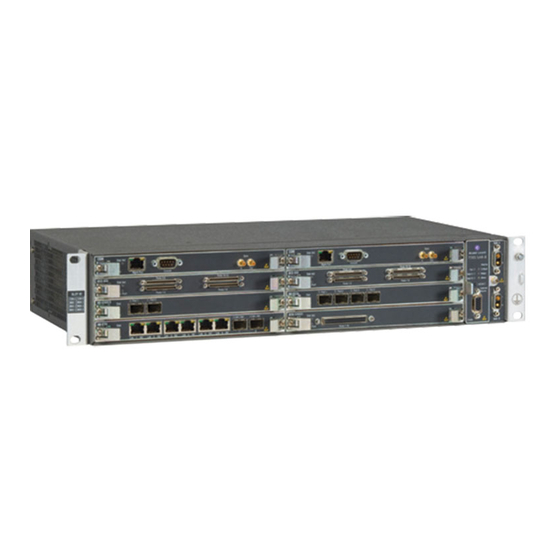
Ba tt. B 19634 Note: The 7705 SAR-F and the 7705 SAR-8 are products in the SAR product line. The main difference between these products is their hardware configuration. The 7705 SAR-F has a fixed, single circuit board configuration while the 7705 SAR-8 is an 8-slot modular Notes on 7705 SAR-8 and 7705 SAR-F on page 59 configuration. -
Page 45: Csm
MDA 4 MDA 5 MDA 6 19635 The 7705 SAR-8 supports two variants of the CSM: a –48 VDC variant and a +24 VDC variant. The Control and Switching Module (CSM) has three main functions: • it provides the management and console interfaces to the 7705 SAR-8 •... -
Page 46: Adapter Cards
Console 19636 There must be at least one CSM installed in the 7705 SAR-8. Install two CSMs for system redundancy. The redundant CSM operates in standby mode and takes over system operation if the active (primary) CSM fails. CSMs are field-replaceable and hot-swappable. Refer to 7705 SAR OS Basic System Configuration Guide for information on CSM redundancy. - Page 47 Synchronous Ethernet as a timing source, has more memory for storage of MPLS labels, and supports a +24 VDC variant. For more information on Synchronous Ethernet, see the 7705 SAR OS Basic System Configuration Guide. • The electrical SFP (part number 3HE00062AA) does not support Synchronous Ethernet.
-
Page 48: Filler Plates
19638 Power System The 7705 SAR-8 has two power connectors mounted on the front of the chassis. These connectors provide access for two independent –48/–60 VDC power feeds, providing power redundancy for the system. When only one power feed is used, the system does not have power supply redundancy. -
Page 49: Fan Module
7705 SAR-8 Overview The 7705 SAR-8 can also be used for +24 VDC operation. This requires that +24 VDC variants of the Fan module, CSM, T1/E1 ASAP Adapter card, and Ethernet Adapter card be installed in the chassis. The +24 VDC variants are identified by a yellow label located on the faceplate. - Page 50 • amber: fans have turned off due to a low temperature or a fan has failed (the 7705 SAR software can detect which situation has occurred and will raise an alarm if a fan failure exists) •...
- Page 51 • The air temperature inside the 7705 SAR-8 is continually monitored by a hardware- controlled temperature switch on the fan module. Fans turn ON when the temperature at the switch exceeds 107°F (42°C) and OFF when the temperature drops below 89°F (32°C).
-
Page 52: Distribution Panels And Cables
17 to 32. Note: A set of connectors consists of one MAIN connector and one SPARE connector. When connecting to 16-port T1/E1 ASAP Adapter cards, always use the (bottom) connectors labeled MAIN. Page 52 7705 SAR-8 Installation Guide... -
Page 53: 7705 Sar-8 Overview
17 to 32. Note: A set of connectors consists of one MAIN connector and one SPARE connector. When connecting to 16-port T1/E1 ASAP Adapter cards, always use the (bottom) connectors labeled MAIN. 7705 SAR-8 Installation Guide Page 53... -
Page 54: Figure 11: Mini-Coaxial Distribution Panel
16-port T1/E1 ASAP Adapter cards, always use the (bottom) connectors labeled MAIN. Figure 12: RJ-45 Distribution Panel Front Back SPARE SPARE RX 1 - 16 MAIN MAIN RX 1 - 16 19604 Page 54 7705 SAR-8 Installation Guide... -
Page 55: Figure 13: 6-Port V.35 Distribution Panel
Figure 14: 6-Port V.35 Distribution Panel M34 Pinouts (Female) P GND S GND TXD (A) RXD (A) TXD (B) RXD (B) XCLK (A) SCR (A) XCLK (B) SCR (B) SCT (A) SCT (B) M34 female 20419 7705 SAR-8 Installation Guide Page 55... -
Page 56: Figure 15: 6-Port Rs-232 Distribution Panel
DB25 connector pinouts. Figure 15: 6-Port RS-232 Distribution Panel RS232 Distribution Panel xxxxxxxxxx Front Rear 20420 Figure 16: 6-Port RS-232 Distribution Panel DB25 Pinouts (Female) Frame GND S GND XCLK 2 XCLK1 DB25 female 20421 Page 56 7705 SAR-8 Installation Guide... -
Page 57: Table 4: T1/E1 Cables
For pinout information on the cables listed above, refer to the 7705 SAR 16-port T1/E1 ASAP Adapter Card Installation Guide. For information about wire identification by color, Wire Identification by Color on page 113. - Page 58 7705 SAR-8 Overview For pinout information on the Serial Data Interface card V.35 and RS-232 cables, refer to the Serial Data Interface Card Installation Guide. Page 58 7705 SAR-8 Installation Guide...
-
Page 59: Notes On 7705 Sar-8 And 7705 Sar-F
7705 SAR-8 Overview Notes on 7705 SAR-8 and 7705 SAR-F The 7705 SAR-8 and the 7705 SAR-F run the same operating system software. The main difference between the products is their hardware platforms. The 7705 SAR-8 has an 8-slot chassis that supports two CSMs, six adapter cards, and a Fan module. The 7705 SAR-F chassis has a fixed hardware configuration. - Page 60 7705 SAR-8 7705 SAR-F Notes 8-port Ethernet Adapter 8 individual Ethernet The –48 VDC versions of the 7705 SAR-8 support two card ports on the faceplate versions of the 8-port Ethernet Adapter card, with version 2 having additional support for Synchronous Ethernet.
-
Page 61: Sar System Installation Process
7705 SAR-8 Overview SAR System Installation Process To install the 7705 SAR-8 system, perform the installation procedures in the following order: Prepare the site. Step 1. Unpack the chassis. Step 2. Mount and ground the chassis. Step 3. Prepare and connect the DC input power cables. - Page 62 7705 SAR-8 Overview Page 62 7705 SAR-8 Installation Guide...
-
Page 63: Site Preparation
Site Preparation In This Chapter This chapter provides information about preparing your site to install a 7705 SAR-8: • Warnings and Notes on page 64 • System Specifications on page 66 → Chassis Specifications on page 66 → Environmental Specifications on page 66 →... -
Page 64: Warnings And Notes
Warnings and Notes Warnings: • Do not transport and relocate a 7705 SAR-8 chassis that has any cards or modules installed. To properly transport and relocate a 7705 SAR-8 chassis, do the following: → label cards and modules to facilitate reassembly (optional) →... -
Page 65: Site Preparation
When mounting the router in a rack, ensure that the rack complies with all Chassis Location Requirements on page 72 requirements outlined in • The 7705 SAR-8 includes factory-installed rack-mounting brackets to mount in a 19-inch equipment rack. 7705 SAR-8 Installation Guide Page 65... -
Page 66: System Specifications
Site Preparation System Specifications Chassis Specifications Table 6: 7705 SAR-8 Chassis Specifications Parameter Description Dimensions (3.5 x 17.5 x 9.8 in.) (H x W x D) (without mounting brackets) (8.9 x 44.4 x 25 cm) Chassis weight (unpopulated) 8.4 lbs (3.8 kg) Chassis weight 16 lbs (7.3 kg) - Page 67 1. Short-term is a period of less than 96 consecutive hours and a total of no more than 15 days per year. This is equivalent to 360 hours per year, with short-term periods occurring no more than 15 times per year. 2. Pollution degree is as defined in IEC 60950. 7705 SAR-8 Installation Guide Page 67...
-
Page 68: Adapter Card Specifications
0.88 lbs (0.4 kg) Fan Module Specifications Table 10: Fan Module Specifications Parameter Description Dimensions (H x W x D) (3.32 x 0.9 x 8.7 in.) (8.43 x 2.24 x 22.0 cm) Weight 0.81 lbs (0.37 kg) Page 68 7705 SAR-8 Installation Guide... -
Page 69: Component Power Consumption
+24 VDC systems. When configuring the system, ensure that the combination of adapter cards (along with the CSM and Fan module) does not exceed this limit. Refer to the individual 7705 SAR-8 adapter card installation guides for more information on these components. -
Page 70: Component Operating Requirements
DC power harness Note: 1. DC power harnesses are available from Alcatel-Lucent. Each harness has two wires. Use two harnesses when redundant DC supplies are used. All power cables used on the 7705 SAR-8 chassis must meet local safety codes. Page 70... -
Page 71: Installation Locations
Site Preparation Installation Locations The 7705 SAR-8 is intended to be installed in facilities that provide weather protection and a temperature-controlled environment. The facilities provide protection from mold growth, pest incursion, and precipitation. Warning: Follow the equipment rack manufacturer’s instructions for proper rack installation. -
Page 72: Chassis Location Requirements
(65°C) under full system power loading combined with worst-case environmental deployment conditions per GR-63. • Ensure that the 7705 SAR-8 system intake is not located immediately adjacent to the exhaust of another chassis such that preheated air above 149°F (65°C) is drawn into the system. -
Page 73: Table 13: Chassis Clearance Specifications
Table 13: Chassis Clearance Specifications Description Front: 2.5 in. (6.4 cm) required for cable management Rear: No clearance required Side: 3 in. (7.6 cm) minimum required for airflow Rack upright: 5 in. (12.7 cm) maximum required for airflow 7705 SAR-8 Installation Guide Page 73... -
Page 74: Safety Considerations
Electrostatic discharge (ESD) damage can occur if components are mishandled. Always wear an ESD-preventive wrist or ankle strap connected to a nearby ground point that is connected to a site grounding point (typically, the grounding stud on the 7705 SAR-8, or a properly grounded rack or work bench). -
Page 75: Cbn And Ibn Support
• In a CBN installation, if you use the 7705 SAR-8 chassis ground stud (located on the right-hand side mounting bracket) to connect the chassis ground terminal(s) to the frame ground on the rack, then you must use a second nut on the stud to secure the attachment. -
Page 76: Power
7705 SAR-8. DC Power Requirements • A means of disconnect must be provided within 10 ft (3 m) of the 7705 SAR-8. • A circuit breaker or fuse with the following recommended ratings must be provided: →... -
Page 77: Fan Module
The 7705 SAR-8 supports a field-replaceable Fan module housing eight fans. The Fan module is replaceable as a single unit; individual fans are not replaceable. The 7705 SAR-8 cooling system requires a minimum of 3 in. (7.6 cm) of unrestricted, unobstructed airflow on each side of the chassis to function properly . - Page 78 Site Preparation Page 78 7705 SAR-8 Installation Guide...
-
Page 79: Installing The Chassis
Installing the Chassis In This Chapter This chapter provides information on installing a 7705 SAR-8 chassis: • Unpacking the Chassis on page 80 → Unpacking Precautions on page 80 • Installing the Chassis in a Rack on page 82 →... -
Page 80: Unpacking The Chassis
The Control and Switching Module (CSM), adapter cards, Fan module, and cables are field- installable and field-replaceable components. Refer to Installing the Components on page 95 for more details. The DC power connectors are part of the 7705 SAR-8 chassis and are not field-replaceable. Warning: •... -
Page 81: Table 15: Unpacking The 7705 Sar-8 Chassis
Installing the Chassis Figure 18 displays the components of a packed 7705 SAR-8 chassis. Figure 18: Unpacking the 7705 SAR-8 Chassis 19600 Table 15: Unpacking the 7705 SAR-8 Chassis Description Shipping container 7705 SAR-8 chassis (wrapped in an anti-static bag) -
Page 82: Installing The Chassis In A Rack
It is easier to install the 7705 SAR-8 chassis in the rack with two people, one person to hold the router and one person to secure it to the rack. Page 82... -
Page 83: Table 16: Rack-Mounting The 7705 Sar-8 Chassis
Installing the Chassis Figure 19: Installing the 7705 SAR-8 Chassis in a Rack Stat SLOT ID CSM A CSM B Sync MDA 1 MDA 2 Mgmnt Port Batt. A MDA 3 MDA 4 Console MDA 5 MDA 6 A16-C ND31... - Page 84 Phillips screws To install the chassis in the rack: Lift the 7705 SAR-8 from the bottom and position it in the rack. If two people are Step 1. installing the chassis, position one person in front of the rack and one behind it.
-
Page 85: Chassis Ground Wiring
• All surfaces that are used for intentionally grounding the 7705 SAR-8 must be brought to a bright finish, and an antioxidant solution must be applied to the surfaces being joined. -
Page 86: Table 17: Ground Wire Descriptions
Figure 21: Attaching the Chassis Ground Connector 19599 Table 18: Chassis Ground Connection Description Lance Cable tie Chassis ground stud (4 mm diameter, nominal) Star washer (optional) Ring lug and chassis ground wire (green/yellow) Page 86 7705 SAR-8 Installation Guide... - Page 87 Connect the opposite end of the ground wire to the appropriate ground point at your Step 7. installation site. Ensure that the chassis ground connection is made according to local safety codes. Connect the 7705 SAR-8 to the DC power source. See DC Power Connections. Step 8.
- Page 88 Installing the Chassis Page 88 7705 SAR-8 Installation Guide...
-
Page 89: Dc Power Connections
This chapter provides information about wiring and connecting the DC power source to the 7705 SAR-8: • Wiring and Connecting DC Power on page 90 → Warnings and Notes on page 90 • DC-Input Power Connections on page 91 → Wiring the DC Inputs on page 91 7705 SAR-8 Installation Guide Page 89... -
Page 90: Wiring And Connecting Dc Power
Notes: • The 7705 SAR-8 requires a minimum of one DC power source to operate, but using two DC power sources is recommended for redundancy. • The 7705 SAR-8 is suitable for both DC-I and DC-C power configurations. -
Page 91: Dc-Input Power Connections
Wiring the DC Inputs The 7705 SAR-8 has two D-Sub 2W2 connectors mounted on the front of the chassis. These connectors are the DC power feed points for DC source voltage from the DC circuit. The following wiring harnesses are available from Alcatel-Lucent to facilitate the DC source-to- router connection. -
Page 92: Table 19: Dc Power Connection Descriptions
-VDC (male pin on power cable connector, blue wire) Note: 1. For D-Sub 2W2 connectors located on the 7705 SAR-8 chassis, the male pin is the positive (+) input terminal and the female pin is the negative (-) input terminal. -
Page 93: For -48 Vdc Installations
Check that the DC supply wiring is correct. Step 5. Attach the connector on the power harness to the D-Sub 2W2 connector on the Step 6. 7705 SAR-8. Install the other 7705 SAR-8 components. See Installing the Components. Step 7. 7705 SAR-8 Installation Guide... -
Page 94: For +24 Vdc Installations
Check that the DC supply wiring is correct. Step 5. Attach the connector on the power harness to the D-Sub 2W2 connector on the Step 6. 7705 SAR-8. Install the other 7705 SAR-8 components. See Installing the Components. Step 7. Page 94... -
Page 95: Installing The Components
Installing the Components In This Chapter This chapter provides information about installing the components in the 7705 SAR-8: • Installing Components on page 96 → Warnings and Notes on page 96 → CSM on page 96 → Fan Module on page 99 →... -
Page 96: Installing Components
Always place components on an anti-static surface. • Do not power up a 7705 SAR-8 before verifying that all common equipment (chassis, power, cooling, and grounding) is connected properly and that the fan module and all cards in the chassis have the same voltage type. -
Page 97: Installing The Components
Installing the Components The 7705 SAR-8 cannot boot without a CSM installed. CSMs are installed in slots A and B. Install a CSM in slot A for a simplex control configuration. Install two CSMs one in slot A — and another in slot B for a redundant control configuration. -
Page 98: Compact Flash
TiMOS-m.n.Yz → m – major release number → n – minor release number → Y – A (alpha release), B (beta release), M (maintenance release), or R (released software) → z – version number Page 98 7705 SAR-8 Installation Guide... -
Page 99: Fan Module
PC and then transferring the files to the new compact flash • accessing a 7705 SAR node via FTP and transferring the files from the node to the new compact flash Fan Module The Fan module has eight fans mounted on its circuit board. -
Page 100: Warnings And Notes
Danger: Always keep your fingers away from rotating fan blades. Warning: The Fan module is hot-swappable. The 7705 SAR-8 operates safely for up to 4 minutes while you replace the Fan module. If a longer maintenance time is required, power off the system to prevent over-heating conditions. -
Page 101: Adapter Cards
2-port OC3/STM1 Channelized Adapter card • 12-port Serial Data Interface card Adapter cards are installed in slots MDA 1 through MDA 6. The 7705 SAR-8 supports up to six adapter cards, in any combination that does not exceed the maximum. See Figure 5 on page 45 for slot identification. -
Page 102: Table 23: Adapter Card Installation Features
Mino r Ports 1-16 Exte rnal Alarm s Ba tt. B 19643 Table 23: Adapter Card Installation Features Description Slot guide Threaded receptacle Captive screw Ejector lever Tools required: • torque driver for Phillips screws Page 102 7705 SAR-8 Installation Guide... -
Page 103: Sfps
SFPs A small form-factor pluggable (SFP) module can be installed on the 8-port Ethernet Adapter card, the 4-port OC3/STM1 Clear Channel Adapter card, and the 2-port OC3/STM1 Channelized Adapter card. 7705 SAR-8 Installation Guide Page 103... -
Page 104: Table 24: Sfp Installation Features
Remove the SFP from the packaging and place it on an anti-static work surface. Step 1. Avoid touching any SFP components and connector pins. Insert the SFP into the appropriate receptacle on the adapter card until it clicks in Step 2. place. Page 104 7705 SAR-8 Installation Guide... -
Page 105: Installing A Distribution Panel In A Rack
Note: There should be at least 1 RU of space above and/or below the 7705 SAR-8 to run cables from the faceplate connectors. It is not necessary for the space to be immediately above or below the 7705 SAR-8. -
Page 106: Table 25: Rack-Mounting The Distribution Panel
Lift the panel and position it in the rack. Ensure that there is at least 1 RU of empty Step 2. space above or below the 7705 SAR-8 to run cables. See Managing Cable Connections to Adapter Cards on page 109. -
Page 107: Disconnecting A 1.0/2.3 Mini-Coaxial Cable From A Distribution Panel
Figure 30: Mini-Coaxial Connector Disconnection Tool 20008 Figure 31: Disconnecting a 1.0/2.3 Mini-Coaxial Cable from a Distribution Panel 19447 Tool required: • disconnection tool for 1.0/2.3 mini-coaxial connectors (supplied with panel) 7705 SAR-8 Installation Guide Page 107... - Page 108 Avoid pulling the tool up and out because the hook may slip off the connector. Warning: Do not pull on the coaxial cable to help disconnect the cable. This may damage the cable. Page 108 7705 SAR-8 Installation Guide...
-
Page 109: Managing Cable Connections To Adapter Cards
Installing the Components Managing Cable Connections to Adapter Cards All cable connections to adapter cards are made from the front of the 7705 SAR-8. The adapter cards can be connected using Ethernet, copper, or fiber-optic cables. A distribution panel is needed to make coaxial cable connections. Refer to the appropriate adapter card installation guide for details on connecting to a specific adapter card. -
Page 110: Ethernet And Copper Cables
RU space left below the 7705 SAR; cables for the cards in the upper half of the chassis are routed above the unit. If desired, loosely bundle the cables from each slot together using a cable tie. -
Page 111: T3/E3 Sfp Connections
Fiber-optic cables are routed in a similar fashion to Ethernet and copper wire cables (see Figure 32). Cables are routed under or over the chassis. Hardware required: • fiber cable boot (optional) • cable ties (optional) 7705 SAR-8 Installation Guide Page 111... -
Page 112: Making A Shield Ground Connection
Nicks can weaken or break a conductor or expose a wire to a potential short circuit. Separate the ground shield (braid, foil, and drain wire) from the signal conductors. Step 3. Page 112 7705 SAR-8 Installation Guide... -
Page 113: Wire Identification By Color
To maintain signal integrity, wires should not be untwisted more than 0.5 in (13 mm). Table 26: Quad Identification Wire Color Quad Number Unique Wire Color Identified ❑ Blue ❑ Orange ❑ Green ❑ Brown ❑ Gray ❑ ❑ Black ❑ Yellow 7705 SAR-8 Installation Guide Page 113... -
Page 114: Making External Synchronization Connections
The CSM provides 1.0/2.3 coaxial connectors for external synchronization input and output. For redundant CSM configurations where both CSMs use the same synchronization signal, a Sync Y-cable (available from Alcatel-Lucent) connects the Sync In connectors on both CSMs to each other. The external synchronization source cable connects to the piggyback connector on the CSM A Sync In side. -
Page 115: Connecting An External Synchronization Input
1.0/2.3 coaxial connector (for connection to external synchronization source) • Sync Y-cable available from Alcatel-Lucent (for redundant CSM systems) (part number 3HE03401AA) Connecting an External Synchronization Input To connect an external synchronization source input to the router: For single CSM systems, attach the synchronization cable to the Sync In connector Step 1. - Page 116 Installing the Components Page 116 7705 SAR-8 Installation Guide...
-
Page 117: Initializing And Provisioning
Running Telnet on page 123 • Provisioning CSM and Adapter Card Parameters on page 124 → Card and Card-Type Commands on page 124 → MDA and MDA-Type Commands for Adapter Cards on page 125 7705 SAR-8 Installation Guide Page 117... -
Page 118: Powering Up The Router
Then power up the system and verify the LED activity of all components. The primary copy of the 7705 SAR-8 TiMOS software is located on the compact flash memory device that is factory-installed on the CSM. -
Page 119: Troubleshooting Initial Startup
(Optional at this time) Assign an IP address to the CSM. Refer to Telnet Connection Step 5. for quick reference information and to the 7705 SAR OS Basic System Configuration Guide for detailed information. (Optional at this time) Configure or modify the primary, secondary, or tertiary BOF Step 6. -
Page 120: Figure 34: Files On The Compact Flash
— Major release number n — minor release number Y: A — Alpha release B — Beta release M — Maintenance release R — Released software z — Version number both.tim — Application software file Page 120 7705 SAR-8 Installation Guide... -
Page 121: Establishing Router Management Connections
Initializing and Provisioning Establishing Router Management Connections There are two ways to access management of the 7705 SAR-8: • Console connection • Telnet connection Console Connection The console port on the CSM is a male DB9 connector. To establish a console connection, you need the following: •... -
Page 122: Telnet Connection
[0..32] For more information about configuring router parameters, refer to the 7705 SAR OS Router Configuration Guide. For pinout information, refer to Management Port Pinouts on page 151. -
Page 123: Running Telnet
To establish a Telnet connection, run a Telnet program and issue the Telnet command, followed by the IP address. The following displays an example of a Telnet login: C:\>telnet 192.168.1.xx1 Login: admin Password: ######## ALU-1# The default login is admin. The default password is admin. 7705 SAR-8 Installation Guide Page 123... -
Page 124: Provisioning Csm And Adapter Card Parameters
In the config context, activate the IOM on the CSM using the card and card-type CLI commands to specify the IOM. Note: For the 7705 SAR-8, when specifying the IOM, the slot number value is always 1 and the card type is always iom-1g. -
Page 125: Mda And Mda-Type Commands For Adapter Cards
In the show context, adapter cards are identified as “1/n”, where “1” is the slot number and “n” is the mda-number. For example, the command show mda 1/5 displays information on the adapter card in slot MDA 5. For the 7705 SAR-8, the slot number is always 1. -
Page 126: Example
1 mda-type a8-eth exit mda 2 mda-type a16-chds1 exit exit ---------------------------------------------- ALU-1>config# To configure ports, refer to the Card and Port Configuration section of the 7705 SAR OS Interface Configuration Guide. Page 126 7705 SAR-8 Installation Guide... -
Page 127: Appendix A: Connectors And Leds
In This Chapter This chapter provides information on the connectors and LEDs seen on the front of the 7705 SAR-8. There are no connectors or LEDs on the back of the unit: • CSM Connectors and LEDs on page 128 •... -
Page 128: Csm Connectors And Leds
Sync Mgmt Port Console 19647 Table 29 describes the connectors and LEDs on the CSM. Table 29: 7705 SAR-8 CSM Connector and LED Descriptions Label/Part Description category — Blue: Indicates that power to the CSM is on Unlit: Indicates that there is no power to the CSM or the power is faulty Stat (Status) —... - Page 129 Appendix A: Connectors and LEDs Table 29: 7705 SAR-8 CSM Connector and LED Descriptions (Continued) Label/Part Description category Mgmt Port Connector The Ethernet Management port has an RJ-45 connector and is used for the initial system startup as well as system configuration and monitoring. It supports both half and full duplex modes, and 10M/100M or autonegotiated communication.
-
Page 130: Fan Module Connectors And Leds
Green: Indicates that the fans are operational Amber: Indicates that the fans have turned off due to a low temperature or that a fan has failed (the 7705 SAR software can detect which situation has occurred and will raise an alarm if a fan failure exists) Unlit: Indicates that the fan has power failure Note: The FAN LED is not affected by a Lamp Test. - Page 131 Appendix A: Connectors and LEDs Table 30: 7705 SAR-8 Fan Module Connector and LED Descriptions (Continued) Label/Part Description category Batt A — Green: Indicates that DC input power is present and operational Batt B Unlit: Indicates that the DC power supply is not installed or the DC power feed is not connected Note: The Batt A and Batt B LEDs are not affected by a Lamp Test.
- Page 132 Appendix A: Connectors and LEDs Table 30: 7705 SAR-8 Fan Module Connector and LED Descriptions (Continued) Label/Part Description category External Connector The External Alarms port is a DB15 serial port. It can receive input Alarms signals from four external alarm devices and provide output signals through three sets of contacts.
-
Page 133: Adapter Card Connectors And Leds
Appendix A: Connectors and LEDs Adapter Card Connectors and LEDs Adapter card connectors and LEDs are described in the specific adapter card installation guide. 7705 SAR-8 Installation Guide Page 133... - Page 134 Appendix A: Connectors and LEDs Page 134 7705 SAR-8 Installation Guide...
-
Page 135: Appendix B: Field-Replaceable Units
Appendix B: Field-Replaceable Units In This Chapter This chapter provides information about field-replaceable units (FRUs) in the 7705 SAR-8 chassis: • Warnings and Notes on page 136 • Replacing a CSM on page 137 • Replacing Adapter Cards on page 140 •... -
Page 136: Warnings And Notes
Dangers: • Only trained and qualified personnel should install or replace this equipment. • Use of procedures other than those specified in this 7705 SAR-8 Installation Guide can result in hazardous radiation exposure. Warnings: • Electrostatic discharge (ESD) damage can occur if 7705 SAR-8 components are mishandled. -
Page 137: Replacing A Csm
• When replacing CSMs, modifying the configuration is not required. • The 7705 SAR-8 requires at least one CSM, which must be installed in slot CSM A. For redundancy, install a second CSM in slot CSM B. • Do not force an adapter card into a CSM slot. -
Page 138: Removing A Csm
Stat MDA 5 MDA 6 Stat 7705 SAR- 8 Sync Sync Mgmn t Port Conso le Alarm Critic al Batt A Majo r Batt B Mino r ACO/L T Exte rnal Alarm s 19603 Page 138 7705 SAR-8 Installation Guide... - Page 139 Pull the card half way out and then reinsert it. Secure the card in place by tightening the captive screws. Do not over-tighten. The Step 4. recommended torque is 4-6 lbf-in. 7705 SAR-8 Installation Guide Page 139...
-
Page 140: Replacing Adapter Cards
Always place components on an anti-static surface. • Do not power up a 7705 SAR-8 before verifying that all common equipment (chassis, power, cooling, and grounding) is connected properly and that the fan module and all cards in the chassis have the same voltage type. -
Page 141: Changing The Adapter Card Configuration
Refer to the 7705 SAR OS Interface Configuration Guide for details on configuring cards and ports. Issue the following commands in the config context to shut down ports, remove the... -
Page 142: Removing An Adapter Card
Batt B Port Mino r Ports 1-16 Exte rnal Alarm s Ba tt. B 19649 Table 31: Adapter Card Installation Features Description Card guide Threaded receptacle Captive screws Ejector lever Tools required: • Phillips screwdriver Page 142 7705 SAR-8 Installation Guide... - Page 143 If you are not replacing the adapter card immediately, cover the adapter card slot with Step 6. a filler plate. See Installing a Filler Plate on page 148 for instructions on installing a filler plate. 7705 SAR-8 Installation Guide Page 143...
-
Page 144: Replacing An Adapter Card
Power LED on the adapter card is lit (blue). Refer to the adapter card installation guide for information on LEDs for the specific adapter card. Reconnect all previously removed network cables to the adapter card ports. Step 6. Page 144 7705 SAR-8 Installation Guide... -
Page 145: Replacing The Fan Module
Note: In the event of a single fan failure, the remaining fans continue to run. This is sufficient to continue to provide adequate cooling for the system, but the Fan module needs to be replaced as soon as possible. The individual fans are not field-replaceable. 7705 SAR-8 Installation Guide Page 145... -
Page 146: Removing The Fan Module
Wait until the fans stop spinning (about 20 seconds) before completely removing the Fan module from its slot. When the fans stop spinning, pull the Fan module completely out of the slot. Step 4. Page 146 7705 SAR-8 Installation Guide... -
Page 147: Replacing The Fan Module
(green), the system is receiving power from power feeds A and/or B. At least one of the Batt LEDs must be lit. Refer to Fan Module Connectors and LEDs on page 130 for more information on Fan module LEDs. 7705 SAR-8 Installation Guide Page 147... -
Page 148: Installing A Filler Plate
Align the filler plate and insert the plate into the chassis slot. Step 1. Tighten the two captive screws that fasten the filler plate to the chassis. Do not over- Step 2. tighten. Filler plates do not have backplane connectors. Page 148 7705 SAR-8 Installation Guide... -
Page 149: Appendix C: Pinout Assignments
Fan Module Port on page 153 → External Alarms Port on page 153 • RJ-45 Distribution Panel on page 156 → RJ-45 Distribution Panel Pinouts on page 156 • Adapter Card Ports on page 157 7705 SAR-8 Installation Guide Page 149... -
Page 150: Csm Ports
This port has an RJ-45 connector on the front panel. You must provide a CAT5 Ethernet cable to connect to the port. Figure 45 shows the Management port pin numbers. Figure 45: Management Port Pin Numbers Pin 8 Pin 1 19593 Page 150 7705 SAR-8 Installation Guide... -
Page 151: Management Port Pinouts
115 200. This port has a DB9 male connector. Connect the Console port to a terminal using an EIA/TIA-232 serial cable. Figure 46 shows the Console port pin numbers. Figure 46: Console Port Pin Numbers 19862 7705 SAR-8 Installation Guide Page 151... -
Page 152: Console Port Pinouts
Description Input Data carrier detect Input Receive data Output Transmit data Output Data terminal ready Signal ground Signal ground Input Data set ready Output Request to send Input Clear to send Input Ring indicator Page 152 7705 SAR-8 Installation Guide... -
Page 153: Fan Module Port
Table 34). State transitions on the inputs are debounced for 2 seconds. Refer to the 7705 SAR OS System Management Guide for information on customizing reporting of external alarm conditions. You can display the status of the alarm inputs using the show>chassis>environment CLI command. -
Page 154: External Alarms Port Pinouts
Major alarm severity (default) Alarm 4 Input Minor alarm severity (default) — Not connected Alarm output 1, pin 2 Output Contact closes on critical alarm Alarm output 1, pin 1 Output Contact closes on critical alarm Page 154 7705 SAR-8 Installation Guide... -
Page 155: Alarm Examples
• a critical external alarm has been detected Major • one or more adapter or CSM cards has reported an over- temperature condition • a major external alarm has been detected Minor • a minor external alarm has been detected 7705 SAR-8 Installation Guide Page 155... -
Page 156: Rj-45 Distribution Panel
RJ-45 Distribution Panel Pinouts Table 36 indicates the pinout assignments. Table 36: RJ-45 Distribution Panel Pinout Assignments Pair Signal Rx Ring Rx Tip — Reserved Tx Ring Tx Tip — Reserved — Shield — Shield Page 156 7705 SAR-8 Installation Guide... -
Page 157: Adapter Card Ports
Appendix C: Pinout Assignments Adapter Card Ports Refer to the appropriate adapter card installation guide for port and pinout information on a specific adapter card. 7705 SAR-8 Installation Guide Page 157... - Page 158 Appendix C: Pinout Assignments Page 158 7705 SAR-8 Installation Guide...
-
Page 159: Standards And Protocol Support
Protocols Generic Requirements, Issue 1, July 1994 RFC 5309 Point-to-Point Operation over LAN in GR-253-CORE - SONET Transport Systems: Link State Routing Protocols Common Generic Criteria. Issue 3, September 2000 AF-PHY-0086.001 Inverse Multiplexing for ATM (IMA) 7705 SAR-8 Installation Guide Page 159... - Page 160 Multiplexing (TDM) over Packet (SAToP) Network Management Protocol (SNMP) RFC 4717 Encapsulation Methods for Transport of Management Frameworks Asynchronous Transfer Mode (ATM) over RFC 3412 Message Processing and Dispatching for MPLS Networks the Simple Network Management Protocol (SNMP) Page 160 7705 SAR-8 Installation Guide...
- Page 161 SSH Protocol TIMETRA-OAM-TEST-MIB.mib Architecture TIMETRA-PORT-MIB.mib draft-ietf-secsh-userauth.txt SSH Authentication TIMETRA-PPP-MIB.mib Protocol TIMETRA-QOS-MIB.mib draft-ietf-secsh-transport.txt SSH Transport Layer TIMETRA-ROUTE-POLICY-MIB.mib Protocol TIMETRA-RSVP-MIB.mib draft-ietf-secsh-connection.txt SSH Connection TIMETRA-SAP-MIB.mib Protocol TIMETRA-SDP-MIB.mib draft-ietf-secsh- newmodes.txt SSH Transport Layer TIMETRA-SECURITY-MIB.mib Encryption Modes TIMETRA-SERV-MIB.mib TIMETRA-SYSTEM-MIB.mib TIMETRA-TC-MIB.mib 7705 SAR-8 Installation Guide Page 161...
- Page 162 Standards and Protocol Support Page 162 7705 SAR-8 Installation Guide...
- Page 163 Customer documentation and product support Customer documentation http://www.alcatel-lucent.com/myaccess Product manuals and documentation updates are available at alcatel-lucent.com. If you are a new user and require access to this service, please contact your Alcatel-Lucent sales representative. Technical Support http://www.alcatel-lucent.com/support Documentation feedback...
- Page 164 © 2009 Alcatel-Lucent. All rights reserved. 3HE 04949 AAAA TQZZA Edition 01...