Alcatel-Lucent 7705 Installation Manual
Service aggregation router
Hide thumbs
Also See for 7705:
- Service manual (546 pages) ,
- Configuration manual (532 pages) ,
- Interface configuration manual (226 pages)
Table of Contents
Advertisement
Quick Links
Alcatel-Lucent 7705
SERVICE AGGREGATION ROUTER | RELEASE 1.0
S A R - 8 C H A S S I S I N S T A L L A T I O N G U I D E
Alcatel-Lucent Proprietary
This document contains proprietary information of Alcatel-Lucent and is not to be disclosed
or used except in accordance with applicable agreements.
Copyright 2008 © Alcatel-Lucent. All rights reserved.
Advertisement
Table of Contents

Related Manuals for Alcatel-Lucent 7705


Summary of Contents for Alcatel-Lucent 7705
- Page 1 S A R - 8 C H A S S I S I N S T A L L A T I O N G U I D E Alcatel-Lucent Proprietary This document contains proprietary information of Alcatel-Lucent and is not to be disclosed or used except in accordance with applicable agreements.
- Page 2 The customer hereby agrees that the use, sale, license or other distribution of the products for any such application without the prior written consent of Alcatel-Lucent, shall be at the customer's sole risk. The customer hereby agrees to defend and hold Alcatel-Lucent harmless from any claims for loss, cost, damage, expense or liability that may arise out of or in connection with the use, sale, license or other distribution of the products in such applications.
-
Page 3: Table Of Contents
7705 SAR-8 Overview ........ - Page 4 Example ............... . 110 Page 4 7705 SAR-8 Installation Guide...
- Page 5 Index ................139 7705 SAR-8 Installation Guide...
- Page 6 Table of Contents Page 6 7705 SAR-8 Installation Guide...
- Page 7 Component Power Consumption ........... 56 Table 11: 7705 SAR-8 Hardware Components for DC Operational Requirements ..... 57 Table 12: Chassis Clearance Specifications .
- Page 8 Table 27: 7705 SAR-8 Fan Module Connector and LED Descriptions ......114 Appendix B: Field-Replaceable Units .
- Page 9 Installing the 7705 SAR-8 Chassis in a Rack ....... . .
- Page 10 Fan Module Port ............. . . 134 Page 10 7705 SAR-8 Installation Guide...
- Page 11 (first packet of a fragment) Batt A battery A bidirectional forwarding detection boot options file BSTA Broadband Service Termination Architecture base transceiver station common bonding networks committed buffer space control channel customer edge circuit emulation 7705 SAR-8 Installation Guide Page 11...
- Page 12 DC-C DC return - common DC-I DC return - isolated DDoS distributed DoS DHCP dynamic host configuration protocol domain name server denial of service dot1q IEEE 802.1q encapsulation for Ethernet interfaces Page 12 7705 SAR-8 Installation Guide...
- Page 13 Global System for Mobile Communications (2G) HSDPA high-speed downlink packet access HSPA high-speed packet access isolated bonding networks ICMP Internet control message protocol IMA control protocol cells IEEE Institute of Electrical and Electronics Engineers IETF Internet Engineering Task Force 7705 SAR-8 Installation Guide Page 13...
- Page 14 5 algorithm media dependent adapter Metro Ethernet Forum multi-field classification management information base minimum information rate MLPPP multilink point-to-point protocol multilink protocol MPLS multiprotocol label switching Page 14 7705 SAR-8 Installation Guide...
- Page 15 ID peak information rate point of presence point-to-point protocol packet switched network PVCC permanent virtual channel connection pseudowire PWE3 pseudowire emulation edge-to-edge quality of service remote defect indication 7705 SAR-8 Installation Guide Page 15...
- Page 16 TLDP targeted LDP type length value type of service TPID tag protocol identifier tunnel table manager user datagram protocol UMTS Universal Mobile Telecommunications System (3G) Page 16 7705 SAR-8 Installation Guide...
- Page 17 VoIP voice over IP virtual path virtual path connection virtual path identifier virtual private network WCDMA wideband code division multiple access (transmission protocol used in UMTS networks) WRED weighted random early discard 7705 SAR-8 Installation Guide Page 17...
- Page 18 List of Acronyms Page 18 7705 SAR-8 Installation Guide...
-
Page 19: Preface
Control and Switching Module (CSM), adapter cards, and Fan module. After the hardware installation process is completed, refer to the 7705 SAR OS documentation set for details on the boot process, software configuration, and Command Line Interface (CLI) information to configure system and network parameters. -
Page 20: Table 1: Information Symbols
Preface • 7705 SAR OS Quality of Service Guide This guide describes how to configure Quality of Service (QoS) policy management. Warnings and Notes Observe the warnings and notes in this guide to avoid injury or router damage during installation and maintenance. Follow the safety procedures and guidelines when working with and near electrical equipment. - Page 21 Class 1 Laser Product Technical Support If you purchased a service agreement for your 7705 SAR-8 and related products from a distributor or authorized reseller, contact the technical support staff for that distributor or reseller for assistance. If you purchased an Alcatel-Lucent service agreement, contact technical assistance at: Web: http://www1.alcatel-lucent.com/comps/pages/carrier_support.jhtml...
- Page 22 Preface Page 22 7705 SAR-8 Installation Guide...
-
Page 23: Mandatory Regulations
Mandatory Regulations In This Chapter The following sections describe the mandatory regulations that govern the installation and operation of the 7705 SAR-8: • List of Terms on page 24 • General Requirements on page 25 • Canada Regulations on page 28 •... -
Page 24: List Of Terms
Nationally Recognized Testing Laboratory OSHA (USA) Occupational Safety and Health Administration (USA) RoHS Restriction of the use of certain Hazardous Substances SELV Safety Extra Low Voltage Underwriters Laboratories WEEE Waste Electrical and Electronic Equipment Page 24 7705 SAR-8 Installation Guide... -
Page 25: General Requirements
General Requirements The sections that follow outline the mandatory regulations that govern the installation and operation of the 7705 SAR-8. You must adhere to these instructions so that your system meets regulatory requirements. Danger: When removing cards from a shelf under power, some of the components such as the DC converters may be extremely hot. - Page 26 Mandatory Regulations Laser Interface The 7705 SAR-8 uses a fiber-optic communications method and is an FDA and IEC Class 1 Laser product. Only trained service personnel thoroughly familiar with laser radiation hazards should install or remove the fiber-optic cables and cards in this system.
-
Page 27: Figure 1: Protective Earth (Ground)
Mandatory Regulations Regulatory Symbols The 7705 SAR-8 uses various regulatory approvals symbols. They may be used on product markings such as approvals labels. These symbols are described in IEC 417. Figure 1 Figure 2 show symbols of a terminal that you must connect to earth ground before you make any other connections to the equipment. -
Page 28: Canada Regulations
CSA standard C22.2 No. 60950-1. Use the system with a SELV secondary source that is electrically isolated from the AC source and that is grounded reliably. The 7705 SAR-8 is safety certified according to CSA standard C22.2 No. 60950-1 by CSA. Page 28... -
Page 29: United States Regulations
Federal Communications Commission FCC Part 15 Important! Changes or modifications not expressly approved by Alcatel-Lucent could void the user’s authority to operate the equipment. This device complies with Part 15 of the FCC Rules. Operation is subject to the following two conditions: (1) This device may not cause harmful interference, and (2) this device must accept any interference received, including interference that may cause undesired operation. - Page 30 ANSI Z 136.1: Safe Use of Lasers and ANSI Z 136.2: Safe Use of Lasers in Optical Fiber Communications Systems. You can obtain these documents and other instructional material from: Laser Institute of America 12424 Research Parkway, Suite 125 Orlando, FL 32826-3274 Page 30 7705 SAR-8 Installation Guide...
-
Page 31: European Union Regulations
2004/108/EC Directive 1999/5/EC and The technical documentation as required by the Conformity Assessment procedure is kept at the Alcatel-Lucent location that is responsible for this product. For more information please contact your local Alcatel-Lucent Customer Service Organization. EU Compliance Statement... - Page 32 Additionally, reuse, recovery, and/or recycling targets for the return and/or collection of the packaging waste may be established. For more information regarding collection and recovery of packaging and packaging waste within specific jurisdictions, please contact the Environmental Health and Safety organization. Page 32 7705 SAR-8 Installation Guide...
-
Page 33: Figure 3: Weee Symbol For Post-August 13, 2005 Product
Figure 3: WEEE Symbol for post-August 13, 2005 Product Moreover, in compliance with legal requirements and contractual agreements, where applicable, Alcatel-Lucent will offer to provide for the collection and treatment of Alcatel- Lucent products bearing the logo at the end of their useful life, or products displaced by Alcatel-Lucent equipment offers. - Page 34 EU market after 1 July 2006, with various exemptions, including an exemption for lead solder in network infrastructure equipment. Alcatel-Lucent products shipped to the EU after 1 July 2006 comply with the EU RoHS Directive.
-
Page 35: Australia/New Zealand Regulations
7705 SAR-8 in Australia and New Zealand. ACMA Regulations The 7705 SAR-8 complies with the ACMA requirements and the product is marked with the 'A Tick' under the Supplier Code N594. This Class A digital apparatus complies with AS/NZS CISPR22. -
Page 36: China Regulations
For more information regarding collection and recovery of packaging and packaging waste within specific jurisdictions, please contact the Alcatel-Lucent Environmental Health and Safety organization. For installations not performed by Alcatel-Lucent, please contact the Alcatel-Lucent Customer Support Center at: Technical Support Services... - Page 37 Mandatory Regulations In accordance with the People’s Republic of China Electronic Industry Standard “Marking for the Control of Pollution Caused by Electronic Information Product” (SJ/T11364-2006), customers may access Alcatel-Lucent’s Hazardous Substances Table information at either of the following two URLs: •...
- Page 38 Mandatory Regulations Page 38 7705 SAR-8 Installation Guide...
-
Page 39: 7705 Sar-8 Overview
7705 SAR-8 Overview In This Chapter This chapter provides an introduction to the Alcatel-Lucent 7705 SAR-8: • 7705 SAR-8 Components on page 40 → Chassis on page 40 → CSM on page 41 → Adapter Cards on page 42 →... -
Page 40: 7705 Sar-8 Components
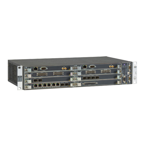
Figure 4 shows the front view of the 7705 SAR-8. There are eight horizontal slots for the CSMs and adapter cards, and one vertical slot for the Fan module. The connectors for the DC power feeds are located to the right of the Fan module and are factory-installed. -
Page 41: Csm
Console 19636 There must be at least one CSM installed in the 7705 SAR-8. Install two CSMs for system redundancy. The redundant CSM operates in standby mode and takes over system operation if the active (primary) CSM fails. CSMs are field-replaceable and hot-swappable. Refer to 7705 SAR OS Basic System Configuration Guide for information on CSM redundancy. -
Page 42: Adapter Cards
Adapter Cards Figure 7 shows a sample adapter card. Adapter cards on the 7705 SAR-8 provide a wide variety of interfaces of different speed and type, including Ethernet (10/100/1000 Base-T and optical), T1/E1 with ATM and IMA, and TDM (channelized and unchannelized). -
Page 43: Slot Covers
19638 Power System The 7705 SAR-8 has two power connectors mounted on the front of the chassis. These connectors provide access for two independent -48/-60 VDC power feeds, providing power redundancy for the system. When only one power feed is used, the system does not have power supply redundancy. -
Page 44: Fan Module
The Fan module is hot-swappable and field-replaceable by qualified personnel. It must always be installed and fully operational while the 7705 SAR-8 is powered up. During routine maintenance and Fan module replacement, the system can operate safely for up to four minutes. - Page 45 If the FAN LED is amber (indicating a fan problem), a Fan Fail Alarm or a Temperature Threshold Alarm is raised and the Fan module should be replaced. 7705 SAR-8 Installation Guide Page 45...
-
Page 46: Distribution Panels
17 to 32. Note: A set of connectors consists of one MAIN connector and one SPARE connector. When connecting to 16-port T1/E1 ASAP Adapter cards, always use the (bottom) connectors labeled MAIN. Page 46 7705 SAR-8 Installation Guide... -
Page 47: 7705 Sar-8 Overview
1 to 16, and the other set is for network ports 17 to 32. Note: A set of connectors consists of one MAIN connector and one SPARE connector. When connecting to 16-port T1/E1 ASAP Adapter cards, always use the (bottom) connectors labeled MAIN. 7705 SAR-8 Installation Guide Page 47... -
Page 48: Table 4: T1/E1 Cables
• 68-pin AMP to 68-pin AMP T1/E1 cable connectors • for equipment connection to a distribution panel For pinout information on the cables listed above, refer to the 7705 SAR 16-port T1/E1 ASAP Adapter Card Installation Guide. Page 48 7705 SAR-8 Installation Guide... -
Page 49: Sar System Installation Process
7705 SAR-8 Overview SAR System Installation Process To install the 7705 SAR-8 system, perform the installation procedures in the following order: Prepare the site. Step 1. Unpack the chassis. Step 2. Mount and ground the chassis. Step 3. Prepare and connect the DC input power cables. - Page 50 SAR System Installation Process Page 50 7705 SAR-8 Installation Guide...
-
Page 51: Site Preparation
Site Preparation In This Chapter This chapter provides information about preparing your site to install a 7705 SAR-8: • Warnings and Notes on page 52 • System Specifications on page 54 → Chassis Specifications on page 54 → Environmental Specifications on page 54 →... -
Page 52: Warnings And Notes
Warnings and Notes Warning: • Do not transport and relocate a 7705 SAR-8 chassis that has any cards or modules installed. To properly transport and relocate a 7705 SAR-8 chassis, do the following: → (optional) label cards and modules to facilitate reassembly →... -
Page 53: Site Preparation
When mounting the router in a rack, ensure that the rack complies with all Chassis Location Requirements on page 59 requirements outlined in • The 7705 SAR-8 includes factory-installed rack-mounting brackets to mount in a 19-inch equipment rack. 7705 SAR-8 Installation Guide Page 53... -
Page 54: System Specifications
System Specifications System Specifications Chassis Specifications Table 5: 7705 SAR-8 Chassis Specifications Parameter Description Dimensions (3.50 x 17.48 x 9.84 in.) (H x W x D) (without mounting brackets) (8.89 x 44.4 x 25 cm) Chassis weight (unpopulated) 8.4 lbs. (3.8 kg) Chassis weight 16.1 lbs. -
Page 55: Adapter Card Specifications
Dimensions (H x W x D) (6.69 x 0.88 x 8.66 in.) (17.0 x 2.24 x 22.0 cm) Weight 0.84 lbs (0.38 kg) (16-port T1/E1 ASAP card) 0.77 lbs (0.35 kg) (8-port Ethernet card) 7705 SAR-8 Installation Guide Page 55... -
Page 56: Csm Specifications
1. In Release 1.0, the chassis itself consumes no power because an external DC power supply provides system power. Thus, power consumption of the chassis with all fans operating is equivalent to the power consumption of the Fan module. Page 56 7705 SAR-8 Installation Guide... -
Page 57: Component Operating Requirements
Note: 1. DC power harnesses are available from Alcatel-Lucent. Each harness has two wires. Use two harnesses when redundant DC supplies are used. All power cables used on the 7705 SAR-8 chassis must meet your local safety codes. 7705 SAR-8 Installation Guide... -
Page 58: Installation Locations
Installation Locations Installation Locations The 7705 SAR-8 is intended to be installed in facilities that provide weather protection and a temperature-controlled environment. The facilities provide protection from mold growth, pest incursion, and precipitation. The 7705 SAR-8 is not intended for installation in outdoor facilities. -
Page 59: Chassis Location Requirements
Chassis Location Requirements on page 59 will impede proper airflow and will result in thermal failure. Note: The Fan module provides 120 CFM of airflow through the 7705 SAR-8 (8 fans at 14.8 CFM/fan). Observe the following requirements when installing the system. -
Page 60: Table 12: Chassis Clearance Specifications
Table 12: Chassis Clearance Specifications Description Front: 2.5 in. (6.4 cm) required for cable management Rear: No clearance required Side: 3 in. (7.6 cm) minimum required for airflow Rack upright: 5 in. (12.7 cm) maximum required for airflow Page 60 7705 SAR-8 Installation Guide... -
Page 61: Safety Considerations
Electrostatic discharge (ESD) damage can occur if components are mishandled. Always wear an ESD-preventive wrist or ankle strap connected to a nearby ground point that is connected to site grounding point (typically, the grounding stud on the 7705 SAR-8, or a properly grounded rack or work bench). - Page 62 Fan module. To use the system in a CBN installation, the 0V RTN terminal must be connected to the frame ground on the rack in which the 7705 SAR-8 is installed. For IBN installations, no additional grounding is needed. Warning: In an IBN installation, the 0V RTN terminal must be connected to the building ground at the source.
-
Page 63: Cabling
• The 7705 SAR-8 is suitable for both DC-I and DC-C power configurations. However, when used in a DC-I configuration, the battery returns must remain isolated until they reach the main power bus. -
Page 64: Fan Module
Safety Considerations DC Power Requirements • A means of disconnect must be provided within 10 ft (3 m) of the 7705 SAR-8. • A maximum 10A circuit breaker or fuse must be provided. • A minimum #18 AWG power conductor must be used for each DC input connection. -
Page 65: Compliance
Site Preparation Compliance Refer to Standards and Protocol Support on page 137 for compliance information. 7705 SAR-8 Installation Guide Page 65... - Page 66 Safety Considerations Page 66 7705 SAR-8 Installation Guide...
-
Page 67: Installing The Chassis
Installing the Chassis In This Chapter This chapter provides information on installing a 7705 SAR-8 chassis: • Unpacking the Chassis on page 68 → Unpacking Precautions on page 68 • Installing the Chassis in a Rack on page 70 →... -
Page 68: Unpacking The Chassis
The Control and Switching Module (CSM), adapter cards, Fan module, and cables are field- installable and field-replaceable components. Refer to Installing the Components on page 83 for more details. The DC power connectors are part of the 7705 SAR-8 chassis and are not field-replaceable. Warning: If the 7705 SAR-8 is to be relocated at a later time, observe the following warning: •... -
Page 69: Table 14: Unpacking The 7705 Sar-8 Chassis
Installing the Chassis Figure 13 displays the components of a packed 7705 SAR-8 chassis. Figure 13: Unpacking the 7705 SAR-8 Chassis 19600 Table 14: Unpacking the 7705 SAR-8 Chassis Description Shipping container 7705 SAR-8 chassis (wrapped in an anti-static bag) -
Page 70: Installing The Chassis In A Rack
It is easier to install the 7705 SAR-8 chassis in the rack with two people, one person to hold the router and one person to secure it to the rack. Page 70... -
Page 71: Table 15: Rack-Mounting The 7705 Sar-8 Chassis
Installing the Chassis Figure 14: Installing the 7705 SAR-8 Chassis in a Rack Stat SLOT ID CSM A CSM B Sync MDA 1 MDA 2 Mgmnt Port MDA 3 MDA 4 Console MDA 5 MDA 6 A16-C ND31 Stat 7705 SAR- 8... - Page 72 Phillips screws To install the chassis in the rack: Lift the 7705 SAR-8 from the bottom and position it in the rack. If two people are Step 1. installing the chassis, position one person in front of the rack and one behind it.
-
Page 73: Chassis Ground Wiring
• All surfaces that are used for intentionally grounding the 7705 SAR-8 must be brought to a bright finish and an antioxidant solution must be applied to the surfaces being joined. -
Page 74: Table 16: Ground Wire Descriptions
Insulation stripped according to local safety code Ring lug Figure 16: Attaching the Chassis Ground Connector 19599 Table 17: Chassis Ground Connection Description Lance Cable tie Chassis ground stud Star washer Ring lug and chassis ground wire (green/yellow) Page 74 7705 SAR-8 Installation Guide... - Page 75 Connect the opposite end of the ground wire to the appropriate ground point at your Step 7. installation site. Ensure that the chassis ground connection is made according to local safety codes. Connect the 7705 SAR-8 to the DC power source. See DC Power Connections on Step 8. page...
- Page 76 Chassis Ground Wiring Page 76 7705 SAR-8 Installation Guide...
-
Page 77: Dc Power Connections
This chapter provides information about wiring and connecting the DC power source to the 7705 SAR-8: • Wiring and Connecting DC Power on page 78 → Warnings and Notes on page 78 • DC-Input Power Connections on page 79 → Wiring the DC Inputs on page 79 7705 SAR-8 Installation Guide Page 77... -
Page 78: Wiring And Connecting Dc Power
Always wear an ESD-preventive wrist or ankle strap and always connect an ESD strap to a nearby ground point that is connected to the site grounding point (typically, the grounding stud on the 7705 SAR-8, or a properly grounded rack or work bench). •... -
Page 79: Dc-Input Power Connections
DC Power Connections Note: • The 7705 SAR-8 requires a minimum of one DC power source to operate, but using two DC power sources is recommended for redundancy. • The 7705 SAR-8 is suitable for both DC-I and DC-C power configurations. -
Page 80: Table 18: Dc Power Connection Descriptions
At the chassis end, attach the 2W2 connector on the wiring harness to the connector Step 4. on the chassis. Use a slot screwdriver to secure the chassis connection by tightening the screws on Step 5. the 2W2 connector. Page 80 7705 SAR-8 Installation Guide... -
Page 81: Dc Power Connections
For redundant configurations, repeat steps 2 through 6 for the second DC power Step 7. source. Install the other 7705 SAR-8 components. See Installing the Components on page Step 8. 7705 SAR-8 Installation Guide Page 81... - Page 82 DC-Input Power Connections Page 82 7705 SAR-8 Installation Guide...
-
Page 83: Installing The Components
Installing the Components In This Chapter This chapter provides information about installing the components in the 7705 SAR-8: • Installing Components on page 84 → Warnings and Notes on page 84 → CSM on page 84 → Fan Module on page 86 →... -
Page 84: Installing Components
• Always place components on an anti-static surface. • Do not power up a 7705 SAR-8 until all components are installed and verified as having been installed correctly. • Use only approved small form-factor pluggable (SFP) fiber-optic devices in adapter card ports. -
Page 85: Table 19: Csm Installation Features
Console, (Ethernet) Management, and Synchronization interfaces. The 7705 SAR-8 cannot boot without a CSM installed. CSMs are installed in slots A and B. Install a CSM in slot A for a simplex control configuration. Install two CSMs one in slot A —... -
Page 86: Fan Module
The Fan module provides an alarm interface equipped with relays that can be used to trigger external alarm indicators. It also provides inputs that can be used to trigger the generation of alarms on the 7705 SAR-8 that indicate environmental or external alarm conditions. Refer to External Alarms Port Pinouts on page 135 for pinout definitions. -
Page 87: Warnings And Notes
Always keep your fingers away from rotating fan blades. • The Fan module is hot-swappable. The 7705 SAR-8 operates safely for up to four minutes while you replace the Fan module. If a longer maintenance time is required, power off the system to prevent over-heating conditions. -
Page 88: Adapter Cards
8-port Ethernet Adapter card A maximum of up to six adapter cards may be installed on the 7705 SAR-8 in slots MDA 1 through MDA 6 (up to six 16-port T1/E1 ASAP Adapter cards or up to two 8-port Ethernet Adapter cards). -
Page 89: Table 21: Adapter Card Installation Features
Note: If the adapter card does not seat properly in the backplane, an ejector lever may not be completely rotated inward. Pull the card out half way, adjust the levers, and reinsert the card. 7705 SAR-8 Installation Guide Page 89... -
Page 90: Sfps
Alarm s Ports 1-16 Link A8-E TN Link Stat Link Link Link Link L i n Link Link Link L i n Link Link Link Link Link Link L i n L i n 19667 Page 90 7705 SAR-8 Installation Guide... -
Page 91: Table 22: Sfp Installation Features
Remove the SFP from the packaging and place it on a flat anti-static work surface. Step 1. Avoid touching any SFP components and connector pins. Insert the SFP into the appropriate receptacle on the adapter card until it clicks in Step 2. place. 7705 SAR-8 Installation Guide Page 91... -
Page 92: Installing A Distribution Panel In A Rack
Note: There should be at least 1 RU of space above and/or below the 7705 SAR-8 to run cables from the faceplate connectors. It is not necessary for the space to be immediately above or below the 7705 SAR-8. -
Page 93: Table 23: Rack-Mounting The Distribution Panel
Lift the panel and position it in the rack. Ensure that there is at least 1 RU of empty Step 2. space above or below the 7705 SAR-8 to run cables. See Managing Cable Connections to Adapter Cards on page Align the mounting holes on each bracket to the mounting holes on the rack uprights. - Page 94 → Non-conductive coatings (such as lacquer and enamel) must be removed from threads and other contact surfaces to ensure electrical conductivity. Thread- forming screws with paint piercing washers may be used for this purpose during installation. Page 94 7705 SAR-8 Installation Guide...
-
Page 95: Managing Cable Connections To Adapter Cards
Installing the Components Managing Cable Connections to Adapter Cards All cable connections to adapter cards are made from the front of the 7705 SAR-8. The adapter cards can be connected using Ethernet, copper, or fiber-optic cables. A distribution panel is needed to make coaxial cable connections. Refer to the appropriate adapter card installation guide for details on connecting to a specific adapter card. -
Page 96: Ethernet And Copper Cables
Managing Cable Connections to Adapter Cards Ethernet and Copper Cables Figure 23 illustrates how Ethernet and copper wire cables are routed on the 7705 SAR-8. Cables can be routed under or over the chassis. Figure 23: Managing Cable Connections A8-ETN... -
Page 97: Fiber Cables
Note: Dress the cables such that they do not impede the insertion or removal of field-replaceable units, including the Fan module. Attach the fiber cable to a distribution panel or appropriate connector. Step 3. 7705 SAR-8 Installation Guide Page 97... -
Page 98: Making A Shield Ground Connection
Step 3. Securely attach the shield to the chassis ground point. Use a screw and star washer Step 4. large enough to make a proper ground connection. Use proper cable dressing and strain relief techniques. Page 98 7705 SAR-8 Installation Guide... -
Page 99: Making External Synchronization Connections
CSM A — Sync In CSM B — Y-cable From external synchronization source Hardware required: • coaxial cable with 1.0/2.3 coaxial connector (for single CSM systems) • Y-cable available from Alcatel-Lucent (for redundant CSM systems) 7705 SAR-8 Installation Guide Page 99... -
Page 100: Connecting An External Synchronization Input
Attach the synchronization cable to the Sync Out connector on the CSM. In a Step 1. redundant CSM system, either Sync Out connector can be used. Attach the other end of the synchronization cable to the device requiring a Step 2. synchronization source. Page 100 7705 SAR-8 Installation Guide... -
Page 101: Initializing And Provisioning
Running Telnet on page 107 • Provisioning CSM and Adapter Card Parameters on page 108 → Card and Card-Type Commands on page 108 → MDA and MDA-Type Commands for Adapter Cards on page 109 7705 SAR-8 Installation Guide Page 101... -
Page 102: Powering Up The Router
Then power up the system and verify the LED activity of all components. The primary copy of the 7705 SAR-8 TiMOS software is located on the compact flash memory device that is factory-installed on the CSM. The compact flash device is not field- replaceable. -
Page 103: Troubleshooting Initial Startup
(Optional at this time) Assign an IP address to the CSM. Refer to Telnet Connection Step 5. on page 106 for quick reference information and to the 7705 SAR OS Basic System Configuration Guide for detailed information. (Optional at this time) Configure or modify the primary, secondary, or tertiary BOF Step 6. -
Page 104: Figure 25: Files On The Compact Flash
— Major release number n — minor release number Y: A — Alpha release B — Beta release M — Maintenance release R — Released software z — Version number both.tim — Application image file Page 104 7705 SAR-8 Installation Guide... -
Page 105: Establishing Router Management Connections
Initializing and Provisioning Establishing Router Management Connections There are two ways to access management of the 7705 SAR-8: • Console connection • Telnet connection Console Connection The console connector on the CSM is a male DB9 connector. To establish a console connection, you need the following: •... -
Page 106: Telnet Connection
CLI Syntax CLI Syntax: bof ip-address/mask address [primary|secondary] For more information about configuring router parameters, refer to the 7705 SAR OS Router Configuration Guide. For pinout information, refer to Management Port Pinouts on page 132. Figure 27: Management Port Connection... -
Page 107: Running Telnet
To establish a Telnet connection, run a Telnet program and issue the Telnet command, followed by the IP address. The following displays an example of a Telnet login: C:\>telnet 192.168.1.xx1 Login: admin Password: ######## ALU-1# The default login is admin The default password is admin 7705 SAR-8 Installation Guide Page 107... -
Page 108: Provisioning Csm And Adapter Card Parameters
IOM on the CSM using the config card card-type commands to specify the IOM. Note: For the 7705 SAR-8, when specifying the IOM, the slot number value is always 1 and the card type is always iom-1g. Command Example Step 1. card slot-number card 1 Step 2. -
Page 109: Mda And Mda-Type Commands For Adapter Cards
. For example, the command show mda 1/5 displays n” mda-number information on the adapter card in slot MDA 5. For the 7705 SAR-8, the slot number is always 1. • Adapter cards must be configured before their ports can be configured. -
Page 110: Example
1 mda-type a8-eth exit mda 2 mda-type a16-chds1 exit exit ---------------------------------------------- ALU-1>config# To configure ports, refer to the Card and Port Configuration section of the 7705 SAR OS Interface Configuration Guide. Page 110 7705 SAR-8 Installation Guide... -
Page 111: Appendix A: Connectors And Leds
In This Chapter This chapter provides information on the connectors and LEDs seen on the front of the 7705 SAR-8. There are no connectors or LEDs on the back of the unit: • CSM Connectors and LEDs on page 112 •... -
Page 112: Csm Connectors And Leds
Sync Mgmt Port Console 19647 Table 26 describes the connectors and LEDs on the CSM. Table 26: 7705 SAR-8 CSM Connector and LED Descriptions Label/Part Description category — Blue: Indicates that power to the CSM is on Unlit: Indicates that there is no power to the CSM or the power is faulty Stat (Status) —... -
Page 113: Appendix A: Connectors And Leds
Appendix A: Connectors and LEDs Table 26: 7705 SAR-8 CSM Connector and LED Descriptions (Continued) Label/Part Description category Mgmt Port Connector The Ethernet Management port is provisioned with an RJ-45 port and used for the initial system startup as well as system configuration and monitoring. -
Page 114: Fan Module Connectors And Leds
ACO/LT External Alarms 19648 Table 27 describes the connectors and LEDs on the Fan module. Table 27: 7705 SAR-8 Fan Module Connector and LED Descriptions Label/Part Description category — Green: Indicates that the fans are operational. Amber: Indicates that there is a fan failure. - Page 115 Appendix A: Connectors and LEDs Table 27: 7705 SAR-8 Fan Module Connector and LED Descriptions (Continued) Label/Part Description category Alarms Critical Red: Indicates that a critical condition exists, such as a fan failure or a power feed failure. Unlit: Indicates that there are no critical alarm conditions.
-
Page 116: Adapter Card Connectors And Leds
Adapter Card Connectors and LEDs Adapter Card Connectors and LEDs Adapter card connectors and LEDs are described in the specific adapter card installation guide. Page 116 7705 SAR-8 Installation Guide... -
Page 117: Appendix B: Field-Replaceable Units
Appendix B: Field-Replaceable Units In This Chapter This chapter provides information about field-replaceable units (FRUs) in the 7705 SAR-8 chassis: • Warnings and Notes on page 118 • Replacing a CSM on page 119 • Replacing Adapter Cards on page 122 •... -
Page 118: Warnings And Notes
Warning: • Electrostatic discharge (ESD) damage can occur if 7705 SAR-8 components are mishandled. Always wear an ESD-preventive wrist or ankle strap connected to a nearby ground point that is connected to site grounding point (typically, the grounding stud on the 7705 SAR-8, or a properly grounded rack or work bench). -
Page 119: Replacing A Csm
• When replacing CSMs, modifying the configuration is not required. • The 7705 SAR-8 requires at least one CSM, which must be installed in slot CSM A. For redundancy, install a second CSM in slot CSM B. • Do not force an adapter card into a CSM slot. -
Page 120: Removing A Csm
7705 SAR- 8 Sync Mgmn t Port Sync Conso le Alarm Critic al Batt A Majo r Batt B Mino r ACO/L T Exte rnal Alarm s 19603 Tools required: • torque driver for Phillips screws Page 120 7705 SAR-8 Installation Guide... - Page 121 Pull the card half way out and then reinsert it. Secure the card in place by tightening the captive screws. Do not over-tighten. The Step 4. recommended torque is 4-6 lbf.-in. 7705 SAR-8 Installation Guide Page 121...
-
Page 122: Replacing Adapter Cards
Warning: • Always place components on an anti-static surface. • Do not power up a 7705 SAR-8 until all components are installed and their installation verified. • Use only approved small form-factor pluggable (SFP) fiber-optic devices in adapter card ports. -
Page 123: Changing The Adapter Card Configuration
If you replace an adapter card with the same type, no configuration change is necessary. Refer to the 7705 SAR OS Interface Configuration Guide for details on configuring cards and ports. -
Page 124: Removing An Adapter Card
Majo r Batt B Port Mino r Ports 1-16 Exte rnal Alarm s 19649 Table 28: Adapter Card Installation Features Description Card guide Threaded receptacle Captive screws Ejector lever Tools required: • Phillips screwdriver Page 124 7705 SAR-8 Installation Guide... -
Page 125: Replacing An Adapter Card
7705 SAR Alarm A16- CND 31 Critic al Stat Batt A Majo r Batt B Port Mino r Ports 1-16 ACO/LT Exte rnal Alarm s 19650 Tools required: • torque driver for Phillips screws 7705 SAR-8 Installation Guide Page 125... - Page 126 Power LED on the adapter card is lit (blue). Refer to the adapter card installation guide for information on LEDs for the specific adapter card. Reconnect all previoulsy removed network cables to the adapter card ports. Step 6. Page 126 7705 SAR-8 Installation Guide...
-
Page 127: Replacing The Fan Module
Note: In the event of a single fan failure, the remaining fans continue to run. This is sufficient to continue to provide adequate cooling for the system but the Fan module needs to be replaced as soon as possible. The individual fans are not field-replaceable. 7705 SAR-8 Installation Guide Page 127... -
Page 128: Removing The Fan Module
Wait until the fans stop spinning (about 20 seconds) before completely removing the Fan module from its slot. When the fans stop spinning, pull the Fan module completely out of the slot. Step 4. Page 128 7705 SAR-8 Installation Guide... -
Page 129: Replacing The Fan Module
(green), the system is receiving power from power feeds A and/or B. At least one of the Batt LEDs must be lit. Refer to Fan Module Connectors and LEDs on page 114 for more information on Fan module LEDs. 7705 SAR-8 Installation Guide Page 129... -
Page 130: Installing A Slot Cover
Align the slot cover and insert the cover into the chassis slot. Step 1. Tighten the two captive screws that fasten the slot cover to the chassis. Do not over- Step 2. tighten. Slot covers do not have backplane connectors. Page 130 7705 SAR-8 Installation Guide... -
Page 131: Appendix C: Pinout Assignments
Fan Module Port on page 134 → External Alarms Port on page 134 → External Alarms Port Pinouts on page 135 → Alarm examples on page 136 • Adapter Card Ports on page 136 7705 SAR-8 Installation Guide Page 131... -
Page 132: Csm Ports
Table 29: Ethernet Management Port Pinouts—RJ45 Female Signal Direction Description – Output Differential transmit data positive Output Differential transmit data – negative Input Differential receive data – positive — Not connected — Not connected Input Differential receive data – negative Page 132 7705 SAR-8 Installation Guide... -
Page 133: Console Port
Description Input Data carrier detect Input Receive data Output Transmit data Output Data terminal ready Signal ground Signal ground Input Data set ready Output Request to send Input Clear to send Input Ring indicator 7705 SAR-8 Installation Guide Page 133... -
Page 134: Fan Module Port
You can display the status of the alarm inputs using the show chassis environment CLI command. The port uses a DB15 connector. You must provide an appropriate cable configured according to your alarm panel. Page 134 7705 SAR-8 Installation Guide... -
Page 135: External Alarms Port Pinouts
Major alarm severity (fixed) Alarm 4 Input Minor alarm severity (fixed) — Not connected Alarm output 1, pin 2 Output Contact closes on critical alarm Alarm output 1, pin 1 Output Contact closes on critical alarm 7705 SAR-8 Installation Guide Page 135... -
Page 136: Alarm Examples
• a major external alarm has been detected Minor • a minor external alarm has been detected Adapter Card Ports Refer to the appropriate adapter card installation guide for port and pinout information on a specific adapter card. Page 136 7705 SAR-8 Installation Guide... -
Page 137: Standards And Protocol Support
Encapsulation Methods for Transport of RFC 1350 The TFTP Protocol (Rev. 2) Ethernet over MPLS Networks RFC 1812 Requirements for IPv4 Routers RFC 4717 Encapsulation Methods for Transport of Asynchronous Transfer Mode (ATM) over MPLS Networks 7705 SAR-8 Installation Guide Page 137... - Page 138 TIMETRA-SDP-MIB.mib RFC 2138 RADIUS TIMETRA-SECURITY-MIB.mib RFC 2571 SNMP-FRAMEWORKMIB TIMETRA-SERV-MIB.mib RFC 2572 SNMP-MPD-MIB TIMETRA-SYSTEM-MIB.mib RFC 2573 SNMP-TARGET-&- TIMETRA-TC-MIB.mib NOTIFICATION-MIB RFC 2574 SNMP-USER-BASED-SMMIB RFC 2575 SNMP-VIEW-BASED ACM- RFC 2576 SNMP-COMMUNITY-MIB RFC 2665 EtherLike-MIB RFC 2819 RMON-MIB Page 138 7705 SAR-8 Installation Guide...
-
Page 139: Index
EMC compliance making the ground connection installing installation LEDs cabling operating requirements choosing a location ports DC power requirements provisioning grounding 7705 SAR-8 Installation Guide Page 139... - Page 140 119, 120 field-replaceable units; see FRUs shield ground connection FRUs simplex configurations adapter cards specifications storage specifications fan module Page 140 7705 SAR-8 Installation Guide...
- Page 141 CSM specifications provisioning environmental specifications adapter card parameters 7705 SAR-8 Installation Guide Page 141...
- Page 142 Index fan module specifications power consumption T1/E1 cables temperature troubleshooting system startup unpacking the chassis Y-cable 42, 99, 100 Page 142 7705 SAR-8 Installation Guide...
- Page 143 Customer documentation http://www.alcatel-lucent.com/osds Product manuals and documentation updates are available through the Alcatel-Lucent Support Documentation and Software Download service at alcatel-lucent.com. If you are a new user and require access to this service, please contact your Alcatel-Lucent sales representative. Technical support http://www.alcatel-lucent.com/support...
- Page 144 © 2008 Alcatel-Lucent. All rights reserved. 3HE 03256 AAAA TQZZA Edition 01...